Note : Les descriptions sont présentées dans la langue officielle dans laquelle elles ont été soumises.
CA 02400539 2002-08-16
WO 01/62830 PCT/CA01/00206
POLYMER-BASED NANOCOMPOSITE MATERIALS AND
METHODS OF PRODUCTION THEREOF
FIELD OF THE INVENTION
The present invention relates to polymer based nanocomposite materials
and their methods of production.
BACKGROUND OF THE INVENTION
!n the recent decade, polymer-based nanocomposite materials have
attracted a great deal of attention because of their applications in various
high-
tech applications, such as micromechanical devices, memory storage media,
chemical and biochemical sensors, display devices, and photonic band-gap
materials. Generally, colloid crystals are employed either as templates for
producing ordered 2D or 3D structures, (Holland, BT, Blanford, CF, Stein A.
~ 5 Science 1998, 281, 538; Zahidov, A. A. et al. Science 1998, 282, 897;
Wijnhoven, J. E.G., Vos, W.L. Science 1998, 281, 802; Lenzmann, F., Li, K.,
Kitai, A.H., Stover Chem. Mater. 1994, 6, 156) for example, in the fabrication
of
photonic bang gap materials or on their own right as chemical sensors (Holtz,
J.H., Asher, S.A. Nature 1997, 389, 829) and devices for memory storage
20 (Kumacheva,E.; O. Kalinina; Lilge, L. Adv. Mat. 1999, 11, 231 ).
Recently, a new approach to producing 3D polymer-based
nanocomposites has been proposed. This method employs latex particles
composed of hard cores and somewhat softer shells (Kalinina, O.; Kumacheva.
E. Macromolecules 1999, 32, 4122). United States Patent No. 5,952,131 to
25 Kumacheva et al., the contents of which are incorporated herein by
reference,
discloses a material having a matrix composed of particles having a core resin
and a shell resin. Figure 1a demonstrates the stages in fabrication of such a
nanocomposite material from core-shell latex particles. Core-shell latex
particles,
composed of hard cores and somewhat softer shells, are synthesized at step A.
3o The particles are packed in a close packed array, at step B, and annealed
at
step C at the temperature that is above the glass transition temperature, Tg,
of
the shell-forming polymer (SFP) and below the Tg of the core-forming polymer
(CFP). As a result, the latex shells flow and form a matrix, whereas the rigid
cores form a disperse phase.
35 With this approach, it is known to incorporate functional components into
CA 02400539 2002-08-16
WO 01/62830 PCT/CA01/00206
the CFP. When the diffusion of the functional component between the cores and
the shells is sufficiently suppressed, nanocomposite materials with a periodic
modulation in composition are produced. It is also known to prepare materials
with a direct structure in which fluorescent core particles are embedded into
an
optically inert matrix.
It would be very advantageous to be able to produce a nanocomposite
template array that would enable one to incorporate a wide array of materials,
either organic or inorganic based materials into the template and to
facilitate a
method of rapidly and economically producing a broad range of polymer-based
nanocomposites with periodic modulations in composition and properties. Such
materials would have applications in memory storage, photonic crystals,
micromechanical actuators, devices for telecommunications, interference and
high-refractive index coatings, bio- and chemical sensors.
~5 SUMMARY OF THE INVENTION
The present invention provides a method for producing polymer-based
core-shell nanocomposite structures with numerous combinations of properties
of the constituent particles and the matrix.
The present invention provides polymer-based nanocomposites obtained
2o by synthesizing core-shell particles with organic or inorganic cores and
polymeric shells; arranging them in one-, two-, or three-dimensional arrays,
and
annealing them at the temperature at which polymeric shells flow.
The present invention provides a nanocomposite material, comprising;
a plurality of rigid core particles embedded in a polymeric material and
25 including air voids located in said polymeric material.
The rigid core particles and the soft polymeric shells may have a single-
component or a multicomponent structure providing a route to multicomponent
nanocomposite materials.
The present invention also provides a nanocomposite material,
3o comprising;
a plurality of rigid core particles embedded in a polymeric material, said
rigid core particles comprising multicomponent organic or inorganic materials.
The present invention also demonstrates that the ratio between the
dimensions of the particle cores and shells can be manipulated to produce a
35 material containing voids that may be filled with various species.
2
WO 01/62830 CA 02400539 2002-08-16 pCT/CA01/00206
In another aspect of the present invention there is provided a method of
synthesizing a nanocomposite material, comprising;
coating a plurality of rigid substantially spherical core particles with a
polymeric shell material, said core particles having a radius r~ and said
polymeric
shell material coating said core particles having a thickness I~, selecting
the
radius r~ of the rigid spherical core particles and the shell thickness IS to
satisfy
0.05 < I~;r~ < 0.2, said polymeric material having a glass transition
temperature
above room temperature, the rigid core particles having softening temperature
greater than a softening temperature of said polymeric material such that upon
annealing the polymeric material softens and flows while the rigid core
remains
solid;
producing one of a one-dimensional, two-dimensional and three-
dimensional array with the coated rigid core particles; and
heating said array above the softening temperature of the polymeric
~5 material at which it flows to form a continuous phase having air voids
dispersed
therethrough.
BRIEF DESCRIPTION OF THE DRAWINGS
The method of producing polymer-based core-shell nanocomposite
2o structures according to the present invention, will now be described, by
way of
example only, reference being had to the accompanying drawings, in which:
Figure 1 a is a diagrammatic representation of a Prior Art method of
formation of polymer-based nanocomposite material, stage A: synthesis of the
core-shell particles with hard cores and soft shells, stage B: assembly of
25 particles in a 1 D, 2D, or 3D close-packed structure, stage C: heat
treatment of
the particle compact that leads to flow of soft shells and formation of a
nanocomposite polymer;
Figure 1 b is a diagrammatic representation of a portion of steps B and C
of Figure 1 a the prior art method of formation of polymer-based nanocomposite
3o material using a thick polymeric shell that ensures a continuous void-free
core-
shell composite material;
Figure 2 shows the principle of the preparation of a nanocomposite
material containing voids in accordance with the present invention;
Figure 3 shows a laser confocal fluorescent microscopy image of the
nanocomposite material containing voids, the scale bar is 2 pm, the size of
the
3
WO 01/62830 CA 02400539 2002-08-16 pCT/CA01/00206
fluorescent poly (methyl methacrylate) core particles is 0.5 pm, the thickness
of
the poly (methyl methacrylate) - poly (butyl methacrylate) shells is 0.08 pm;
Figure 4 is an Atomic Force Microscopy image of the nanocomposite
material formed from the core-shell particles with conductive polypyrrol cores
and poly (butyl acrylate) shells;
Figure 5 shows polypyrole cores covered with poly (butyl methacrylate)
(PBMA) particles;
Figure 6 shows core-shell polypyrrole-poly (butyl methacrylate) particle
size as a function of the ratio between the weight concentration of the core-
and
shell-forming particles;
Figure 7 shows the polydispersity of the core-shell polypyrrole-poly (butyl
methacrylate) particles as a function of the ratio between the weight
concentration of the core- and shell-forming particles;
Figure 8 is an Atomic Force Microscopy image of the nanocomposite
material formed from the core-shell particles containing silica cores and poly
(methyl methacrylate) shells, the size of silica particles is 0.6 pm;
Figure 9 is a diagrammatic representation of a method of producing
multilayer cores by using silica particles as templates and attaching titanyl
sulfate or titanium oxide coating to the core particles;
2o Figure 10 shows the mass ratio Ti02/Si02 in the core shell particles as a
function of ratio TiOS04/surface area of Si02, squares are the calculated
ratio,
diamonds are the experimental results obtained by elemental analysis;
Figure 11 shows the structure of Si02 particles as a function of the weight
concentration of titanyl sulfate in dispersion;
25 Figure 12 is a Scanning Electron Microscopy image of the silica particles
(a) and silica particles coated with Ti02 shells (b), the size of silica
particles is
580 nm, the diameter of the Si02-Ti02 particles is 0.78 pm;
Figure 13 is an Atomic Force Microscopy image of the nanocomposite
material formed from the core-shell particles with SiO,-Ti02 cores and poly
30 (methyl methacrylate) shells; and
Figure 14 shows Bragg diffraction patterns of the films formed from the
core-shell particles with Si02-Ti02 cores and poly (methyl methacrylate)
shells.
4
CA 02400539 2002-08-16
WO 01/62830 PCT/CA01/00206
DETAILED DESCRIPTION OF THE INVENTION
The present invention describes a process for producing polymer-based
core-shell nanocomposite structures. Particularly, the invention provides core-
shell nanocomposite structures having periodic voids dispersed throughout the
structure. The invention also provides core-shell nanocomposite structures in
which the cores comprise multi-component constituents in which the differing
constituents may cover the ambit of both organic and inorganic materials and
these structures are produced both with and without periodic voids dispersed
throughout the material.
The schematics of the approach for growing a polymer-based
nanocomposite with a continuous core-shell structure is shown in Figure 1 a.
As
discussed in the introduction, stage A involves the synthesis of the core-
shell
latex particles that consist of a hard core and a somewhat softer shell. The
materials chosen for the synthesis of the core and shell materials must
satisfy
~5 two important requirements. First, the temperature of softening of the core-
forming material (CFM) and the shell-forming polymer (SFM) should be such that
upon annealing the SFM softens and flows while the CFM remains intact.
Second, the shell-forming material must have the glass transition temperature
well above the room temperature. Any possible diffusion of species between the
2o core and the shell during synthesis or during annealing should be
suppressed to
give a distinct or abrupt well defined boundary between the core and shell.
Several non-limiting and purely exemplary examples are given below to
demonstrate different combinations of materials incorporated into the core- or
shell-forming polymers.
Example 1
Formation of the nanocomposite material with voids available for further
incorporation of functional species
The principle of tuning of the structure of the nanocomposite material to
3o incorporate periodic voids is shown in Figure 2. The ratios between the
volume
fractions of the CFM and the SFM leading to formation of the nanocomposite
material with voids is shown in Table 1 in a shadowed area while the fractions
outside of the shadowed section of the Table give a continuous structure. To
form a homogeneous matrix the ratio between the thickness of the shell, I" and
the radius of the core (r~) should exceed 0.2, i.e., IS /r~ < 0.2. When 0.05 <
lsir~ <
5
WO 01/62830 cA 02400539 2002-o8-is pCT/CA01/00206
0.2 , the amount of the CFM is not sufficient to form a continuous matrix and
small voids are left between particles. The recipe of one embodiment of a
synthesis of the core-shell particles with fluorescent polymeric cores and
optically inert polymeric shells leading to this type of structure is given in
Table
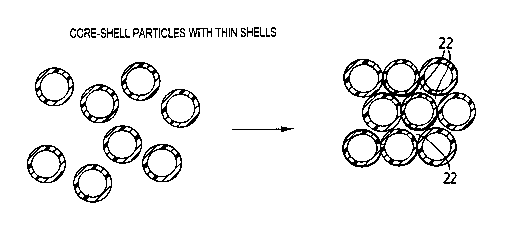
2. It is evident from Figure 2 that the composite structure comprises voids 22
periodically dispersed throughout the material. Figure 3 shows a laser
confocal
fluorescent microscopy image of a nanocomposite material containing voids in
which both the core and shell are polymer materials. Fluorescent cores appear
as bright domains, whereas black domains correspond to air voids available for
?o filing them with different polymer or inorganic materials using
electrochemical
approaches, vacuum deposition, or capillary infiltration with liquid phases.
The
size of the fluorescent poly (methyl methacrylate) core particles is 0.5 pm,
the
thickness of the poly (methyl methacrylate) - poly (butyl methacrylate) shells
is
0.08 pm. The scale bar is 2 Nm.
~5 The cores may be formed of organic, e.g. polymeric materials or inorganic
materials including oxides such as Ti02, Si02 and the like. At the assembly
state
analogous to stage B in Figure 1 a (but with the appropriate core-shell ratios
to
give periodic voids) the core-shell particles are arranged in a one-
dimensional,
two-dimensional, or three-dimensional array by using sedimentation,
2o electrodeposition or centrifugation. Fabrication of the composite material
is
completed by annealing of the dry compact (analogous to stage C in Figure 1
a).
At this stage, the composite material is heated above the softening point of
the
SFM, at which it flows and fills partly or completely voids between the core
particles and forms a continuous phase. In this approach, the SFM should be
25 such that the shells possess enough elasticity to act as a barrier to
prevent the
aggregation of the cores.
The present method disclosed herein provides several levels of control of
the strv cture and function of the nanocomposite. First, the diameters of the
cores
and the thicknesses of the shells may be varied and controlled leading to the
3o variation in particle size and number density in the nanocomposite
material.
Secondly, the shape of the core-shell particles i.e. spherical shape versus a
rod-
like shape, can be manipulated at stage A. Third, the suggested approach
provides several types of morphologies of the ultimate composite material.
When the shells are sufficiently thick, the SFM fills gaps between the core
3~~ particles, i.e., forms a continuous matrix. For thin shells, the rigid
particles are
6
WO 01/62830 CA 02400539 2002-08-16 pCT/CA01/00206
just "glued" together by the SFM. In this way composite materials are formed,
in
which small voids between particles can be filled with another functional
material. Finally, the composition of the CFM and the SFM can be varied and
controlled in a variety of ways, several of which will be described below.
The core-shell particles can be monodispersed or polydispersed
depending on a desired application of the nanocomposite material. To form
nanocomposites with ordered structures, the core particles preferably are
monodisperse, the shells are preferably uniform in thickness, and the entire
core-shell particles are monodispersed. The CFM may be either a single or
multicomponent material. In the multicomponent cores, several species can form
distinct layers or can be mixed to form a homogeneous phase. The
multicomponent materials may be inorganic based materials e.g. oxides, or
multicomponent organic materials, e.g. polymer mixtures, blends and the like.
The structure of the nanostructured material with necks between
~5 monodispersed colloid particles and voids between the particles is similar
to the
structure of templates used for producing photonic band gap materials, (REF)
but has a much better processibility (e.g. it can be polished) and resistance
to
cracking. Due to the presence of voids and ordered structure the material
appears as highly irridiscent, and can be used as diffraction coating or free-
2o standing film. Alternatively, the voids may be filled with photosensitive
materials
such as dyes or chromophores. For example, a monomer covalently labeled or
mixed with a fluorescent dye with the absorption peak similar or different
then
the absorption peaks of the dyes) incorporated in the core and /or core-
forming
polymer may be used for several applications including data storage media.
25 Under imaging of the structure different material morphologies will be
observed
for different wavelengths of irradiation. Local photobleaching of a particular
dye
in the specific lateral or vertical plane will enable one to incorporate a
secret
code in thin coating for security needs.
Alternatively, inorganic, e.g. semiconductor particles may be incorporated
3o into the voids using capillary flow, infiltration or vacuum deposition.
First, upon
dissolution of the particles, octahedral nanostructures will be obtained which
have a very high control over their dimensions and monodispersity. Second
infiltration of a monomer or a polymer mixed with inorganic material, having
nonlinear properties will lead to the periodic modulation of optical
properties of
35 the material.
7
WO 01/62830 CA 02400539 2002-08-16 pCT/CA01/00206
Example 2
Polymer-based nanocomposite material formed from core-shell particles
with electroconductive polymer and dielectric shells
Conductive monodisperse polypyrrole particles with the dimensions
varying 0.08 to 300 pm covered with the dielectric poly (butyl acryalate)
shells
were synthesized using the recipe given in Table 3. A film formed from
polypyrrol
particles showed a finite conductivity. When an elastomeric layer comprised of
a
cross-linked poly (butyl acrylate) was attached to the core particles, a film
formed by annealing of the sediment formed by the core-shell particles showed
conductivity depending on the thickness of the elastomeric shells. Very small
stretching of the film led to significant drop in conductivity. These films
can be
used for non-destructive control of strains in various materials or be
incorporated
in micromechanical devices in which thorough control of small displacements is
~5 required. Figure 4 is an Atomic Force Microscopy image of the nanocomposite
material formed from the core-shell particles with conductive polypyrrol cores
and poly (butyl acrylate) shells.
The polymeric CFM can be represented by a pure polymer or a polymer
which is functionalized by either chemically attached functional groups or
mixing
2o it with appropriate low or high-molecular weight species. When the core-
shell
particles are made from dissimilar materials and the affinity between the core
and the shell material is not sufficient to provide adhesion between the cores
and the shells, interfacial polymerization is not efficient and the shell-
forming
polymer was found to nucleate and polymerize in the bulk rather that on the
25 surface of the core particles. In this situation, the attachment of shells
was
provided by electrostatic attraction between cores and shell-forming particles
synthesized from materials carrying opposite charges, as is shown in Figure 5.
After attachment the shell-forming polymer was annealed to form a dense and
uniform shell, which could be later transformed into a matrix.
3o The amount of the shell-forming polymer to the core- forming polymer had
to provide a dense coverage of the core particles with at least a monolayer of
the shell-forming particles. As is shown in Figures 6 and 7, only under these
conditions core-shell particles with the well-defined size and high
monodispersity
could be produced after coating the core particles.
8
WO 01/62830 CA 02400539 2002-08-16 pCT/CA01/00206
Example 3
Polymer nanocomposites formed by inorganic particles embedded in a
polymeric matrix
Monodispersed silica particles were synthesized using a recipe shown in
Table 4. Poly (methyl methacrylate) shell was attached to the silica
particles,
and a sediment of the core-shell particles was heated at the temperature
leading
to flow of PMMA. Figure 8 shows an Atomic Force Microscopy image of the
nanocomposite material formed from the core-shell particles containing silica
cores and poly (methyl methacrylate) shells. The size of silica particles is
0.6
pm.
Example 4
Polymer nanocomposites formed by multicomponent inorganic particles
embedded in a polymeric matrix
Multilayer cores could be produced by using silica particles as templates
and attaching titanyl sulfate or titanium oxide coating to the core particles,
as is
shown in Figure 9. Monodispersed silica particles were synthesized using a
2o recipe shown in Table 4. A titanium oxide layer was synthesized on the top
of
silica particles using a recipe shown in Table 5. In general, the volume of
Ti02
varied from 0.05 to 0.4 with respect to the volume of the silica particles.
Referring to Figure 10, a very important requirement in the preparation of
monodispersed bilayer inorganic cores is the exact ratio between the surface
25 area of silica particles and the amount of titanyl sulfate added to silica
dispersion. Figure 10 shows the mass ratio Ti02/SiOz in the core shell
particles
as a function of ratio TiOS04/surface area of SiO~. Squares: calculated ratio;
diamonds. The experimental results were obtained by elemental analysis. The
surface area of silica particles in the system was controlled by either silica
3o particle size, or by their concentration in the dispersion. Referring to
Figure 11
shows the structure of the silica particles (Figure 11 a) and coated silica
particles
when titanyl sulfate is deficient (Figure 11 b), in optimum ratio (Figure 11 c
and d),
and in excess, (Figure 11f). Figure 12 is a Scanning Electron Microscopy image
of the silica particles (a) and silica particles coated with Ti02 shells (b).
The size
35 of silica particles is 580 nm, the diameter of the SiO~-Ti02 particles is
0.78 pm.
Figure 13 shows an Atomic Force Microscopy image of the nanocomposite
9
WO 01/62830 CA 02400539 2002-08-16 pCT/CA01/00206
material formed from the core-shell particles with SiOz-Ti02 cores and poly
(methyl methacrylate) shells. Films formed in this manner, showed strong Bragg
diffraction patterns, specifically, Figure 8 shows Bragg diffraction patterns
of the
films formed from the core-shell particles with Si02-Ti02 cores and poly
(methyl
methacrylate) shells.
In such films, the position of the diffraction peak strictly depends on the
dimensions of the cores and shells, therefore such films can be used as
interference high-refractive index polymer-based coatings for, e.g. security
paper. Alternatively, the inorganic particles can be obtained from
1o semiconductors e.g. CdS-CdSe and then coated with a polymeric shell. Upon
annealing the quantum dots will be incorporated in the polymeric matrix
(quantum dots). Materials exhibiting electroactivity may be incorporated into
the
voids.
The multicomponent materials of which the cores and/or shells are
produced may comprise two or more different materials. For example the cores
may be made of two or more several different oxide materials, in layers or a
homogenous mixed oxide. The same applies to the polymeric shell materials, the
multicomponent shells may be made of two or more polymers in blends, block
copolymers and the like.
2o The foregoing description of the preferred embodiments of the invention
has been presented to illustrate the principles of the invention and not to
limit
the invention to the particular embodiment illustrated. It is intended that
the
scope of the invention be defined by all of the embodiments encompassed within
the following claims and their equivalents.
10
WO 01/62830 CA 02400539 2002-08-16 pCT/CA01/00206
Table 9. Volume Fraction of the CFP in the Polymer Nanocomposite
Formed from Core-Shell Particles with the Different Core Diameter and
Shell Thickness.
R~, ~m 0.15 0.20 0.25 0.30 0.35 0.40 0.45 0.50 0.60
L~ = rP
- r~, lam
0.025 42 52 58 63 67 70 73 75 79
0.050 22 30 36 42 47 51 55 58 63
0.075 12 19 24 30 34 38 42 46 51
0.100 8 12 17 22 26 30 33 36 42
0.125 5 9 12 16 20 23 26 30 35
0.150 4 6 9 13 16 19 22 24 30
0.175 3 5 7 10 12 15 18 20 25
0.20 2 4 6 8 10 12 15 17 22
0.25 1 2 4 5 7 9 10 11 18
11
WO 01/62830 CA 02400539 2002-08-16 pCT/CA01/00206
Table 2. Recipe for the Three-Stage Emulsion Polymerization of the
1050 nm Core-Shell Latex Particles
Stage 1 Stage 2 Stage 3
Precha~e:
Deionized water, g 70 70 40
Seeds from previous step, g - 20 20
Potassium persulfate, g 0.2 - -
AIBN, g - 0.005 0.005
Pumping mixture:
MMA, g 30 7 2
BMA, g - -
1
DDM, g 0.088 0.052 0.136
1.068 0.032
EGDMA, g -
NBD-MMA, g 0.01 0.0035
AIBN, g - 0.052 0.186
Ionic initiator solution added simultaneously
with the monomer mixture:
Potassium persulfate, g - - 0.0026
Water, g - -
2.6
Particle size, nm 500 640 745
12
WO 01/62830 CA 02400539 2002-08-16 pCT/CA01/00206
Table 3. Recipe for the synthesis of the core-shell particles with
conductive cores and dielectric shells
Pyrrole, FeCl3 Stabilizer* H20 butyl acrylate DDM KzS204
MI g g ml ml g g
0.3-1.0 5.47 0.3-1.0 100 2 0.13 0.1
* Hydroxy propyl cellulose, poly (ethylene oxide), poly (vinyl alcohol)
Table 4. Recipe for the synthesis of the Si02
Tetraethyl Ethanol % H20 %NH3 Total Reaction Particle size
Orthosilicate, volume, ml Time
ml
20 234 14.4 0.84 300 3 hr 580
nm
20 234 13.8 1.4 300 1 hr 340
nm
20 234 10.25 0.63 285 6 hr 120
nm
Table 5. Recipe for the synthesis of the Si02-Ti02 particles
Silica particles,Silica Volume 0.2 Total reaction,Particle
solid M size
with the diameter,content, TiOS04 in volume, ml nm
%
nm 1 M H2S04,
ml
220 3.0 25 225 260
220 0.8 100 400 1000
580 1.0 40 440 780
13