Sélection de la langue

Search

Sommaire du brevet 2400932 

Énoncé de désistement de responsabilité concernant l'information provenant de tiers

Une partie des informations de ce site Web a été fournie par des sources externes. Le gouvernement du Canada n'assume aucune responsabilité concernant la précision, l'actualité ou la fiabilité des informations fournies par les sources externes. Les utilisateurs qui désirent employer cette information devraient consulter directement la source des informations. Le contenu fourni par les sources externes n'est pas assujetti aux exigences sur les langues officielles, la protection des renseignements personnels et l'accessibilité.

Disponibilité de l'Abrégé et des Revendications

L'apparition de différences dans le texte et l'image des Revendications et de l'Abrégé dépend du moment auquel le document est publié. Les textes des Revendications et de l'Abrégé sont affichés :

  • lorsque la demande peut être examinée par le public;
  • lorsque le brevet est émis (délivrance).
(12) Brevet: (11) CA 2400932
(54) Titre français: ALLUMEUR DOMESTIQUE
(54) Titre anglais: UTILITY LIGHTER
Statut: Durée expirée - au-delà du délai suivant l'octroi
Données bibliographiques
(51) Classification internationale des brevets (CIB):
  • F23Q 2/16 (2006.01)
  • F23Q 2/28 (2006.01)
  • F23Q 2/34 (2006.01)
  • F23Q 2/36 (2006.01)
  • F23Q 3/00 (2006.01)
  • F23Q 13/02 (2006.01)
  • F23Q 13/04 (2006.01)
(72) Inventeurs :
  • DOIRON, GERALD J. (Etats-Unis d'Amérique)
(73) Titulaires :
  • BIC CORPORATION
(71) Demandeurs :
  • BIC CORPORATION (Etats-Unis d'Amérique)
(74) Agent: OSLER, HOSKIN & HARCOURT LLP
(74) Co-agent:
(45) Délivré: 2010-05-11
(86) Date de dépôt PCT: 2001-02-21
(87) Mise à la disponibilité du public: 2001-08-30
Requête d'examen: 2006-02-16
Licence disponible: S.O.
Cédé au domaine public: S.O.
(25) Langue des documents déposés: Anglais

Traité de coopération en matière de brevets (PCT): Oui
(86) Numéro de la demande PCT: PCT/US2001/005538
(87) Numéro de publication internationale PCT: WO 2001063179
(85) Entrée nationale: 2002-08-21

(30) Données de priorité de la demande:
Numéro de la demande Pays / territoire Date
09/510,304 (Etats-Unis d'Amérique) 2000-02-22

Abrégés

Abrégé français

La présente invention concerne un allumeur domestique (10) qui utilise le combustible, le mécanisme d'actionnement (22, 24, 26, 28, 30) et le dispositif de sécurité-enfants d'un briquet de poche (16). De par ses dimensions, cet allumeur domestique est prévu pour recevoir le briquet de poche. L'allumeur domestique définit également dans son carter une partie découpée (44, 46) donnant accès au mécanisme d'actionnement et/ou au dispositif de sécurité-enfants pour sa manipulation par l'utilisateur.


Abrégé anglais


A utility lighter (10), which utilizes the fuel, the actuation
mechanism (22, 24, 26, 28, 30) and/or the child-resistant mechanism of a
pocket
lighter (16), is disclosed. The utility lighter is sized and dimensioned to
receive
the pocket lighter. The utility lighter also defines a cut-out portion (44,
46) on its
housing to expose the actuation mechanism and/or the child-resistant mechanism
therethrough for user manipulation.

Revendications

Note : Les revendications sont présentées dans la langue officielle dans laquelle elles ont été soumises.


8
The embodiments of the present invention for which an exclusive property or
privilege is claimed are defined as follows:
1. A flame producing apparatus comprising:
a body connected to a wand, said body defines a cut-out portion
thereon, said body portion containing a preassembled lighter,
said lighter comprises a piezoelectric ignition device and a fuel
source in fluid communication with a valve movable between a
closed position and an open position, wherein said valve and
ignition device are actuatable by a push-button to selectively
release fuel and to produce a spark;
said lighter further comprises a latch member movable between a
position where the lighter is inoperative and a position where the
lighter is operative;
wherein the flame producing apparatus further comprises an inner tube
disposed within the wand and is in fluid communication with the valve of the
lighter and a nozzle, and wherein the wand and the inner tube are electrically
coupled to the ignition device such that the spark is produced proximate the
nozzle when the ignition device is actuated;
wherein the cut-out portion on the body is sized and dimensioned to
expose the push-button and the latch member for user actuation when the
lighter is received inside the body.
2. The flame producing apparatus of claim 1 further comprises an end cap
adapted to fit on to a first end of the body to retain the lighter within the
body.
3. The flame producing apparatus of claim 2, wherein the nozzle is
located at a second end of the inner tube remote from said first end of the
body.
4. The flame producing apparatus of claim 1, wherein the piezoelectric
ignition device comprises first and second electrodes, said first electrode is

9
electrically coupled to the wand and the second electrode is electrically
coupled to the inner tube.
5. The flame producing apparatus of claim 4 further comprises an
extension, which electrically couples the wand to the first electrode.
6. The flame producing apparatus of claim 4, wherein the extension is
integral with the wand.
7. The flame producing apparatus of claim 5, wherein the first electrode is
slidingly connected to the wand.
8. The flame producing apparatus of claim 5, wherein the first electrode is
slidingly connected to the extension.
9. The flame producing apparatus of claim 5, wherein the first electrode is
movably received in a channel defined by the extension.
10. The flame producing apparatus of claim 1, wherein the inner tube is
rigid.
11. The flame producing apparatus of claim 1, wherein the inner tube is
flexible.
12. The flame producing apparatus of claim 1, wherein in the inoperative
position the latch member is positioned between the push-button and the body.
13. The flame producing apparatus of claim 1, wherein the body defines a
second cut-out portion sized and dimensioned to expose the latch member for
user actuation.

14. The flame producing apparatus of claim 1, wherein the latch member
interferes with the actuation of the push-button in the position where the
preassembled lighter is inoperative and does not interfere with the push-
button
in the position where the preassembled lighter is operative.
15. A flame producing apparatus comprising:
a body connected to a wand, the body containing a preassembled
lighter,
the preassembled lighter comprises a housing containing a piezoelectric
ignition device and a fuel source in fluid communication with a valve
movable between a closed position and an open position, wherein the
valve and ignition device are actuatable by a push-button to selectively
release fuel and to produce a spark;
the preassembled lighter further comprises a latch member movable
between a position where the preassembled lighter is inoperative and a
position where the preassembled lighter is operative;
wherein the flame producing apparatus further comprises a tube in fluid
communication with the valve of the lighter; and a nozzle in the wand, and
wherein the ignition device is electrically coupled such that the spark is
produced proximate the nozzle when the ignition device is actuated;
wherein the body defines a cut-out portion for the push-button that is
sized and dimensioned to expose the push-button for user actuation when the
preassembled lighter is received inside the body;
wherein the body defines a cut-out portion for the latch member that is
sized and dimensioned to expose the latch member for user actuation when the
preassembled lighter is received inside the body.
16. The flame producing apparatus according to claim 15 wherein the
push-button extends through the cut-out.
17. The flame producing apparatus according to claim 15 wherein the latch

11
member is biased to return to the inoperable position after activation.
18. The flame producing apparatus of claim 15, wherein the latch member
interferes with the actuation of the push-button in the position where the
preassembled lighter is inoperative and does not interfere with the push-
button
in the position where the preassembled lighter is operative.
19. A method of manufacturing a flame producing apparatus, comprising
the steps of:
(a) providing at least one outer body component, and a wand, the at
least one outer body component configured and adapted to form at least a
portion of an outer body of the flame producing apparatus, the wand
configured and adapted to connect to the outer body;
(b) providing a preassembled lighter,
the preassembled lighter comprises a piezoelectric
ignition device and a fuel source in fluid communication with a
valve movable between a closed position and an open position,
wherein said valve and ignition device are actuatable by a push-
button to selectively release fuel and to produce a spark;
the preassembled lighter further comprises a latch member
movable between a position where the preassembled lighter is
inoperative and a position where the preassembled lighter is
operative;
(c) inserting the preassembled lighter into the at least one outer
body component, wherein at least one cut-out portion on the at least one body
component is sized and dimensioned to expose the push-button and the latch;
and
(d) mating the valve of the preassembled lighter so that it is in fluid
communication with a nozzle in the wand and electrically coupling the
ignition device of the preassembled lighter such that the spark is produced
proximate to the nozzle when the ignition device is actuated.

12
20. The method of manufacturing a flame producing apparatus of claim 19,
which further comprises an additional step of forming the outer body with at
least one additional outer body component.
21. The method of claim 20, wherein the latch member interferes with the
actuation of the push-button in the position where the preassembled lighter is
inoperative and does not interfere with the push-button in the position where
the preassembled lighter is operative.
22. The method of claim 19, wherein the latch member interferes with the
actuation of the push-button in the position where the preassembled lighter is
inoperative and does not interfere with the push-button in the position where
the preassembled lighter is operative.
23. An extended flame producing apparatus comprising:
a body portion connected to a narrower extended wand portion, the
body containing a preassembled lighter,
the preassembled lighter comprising:
a housing containing a piezoelectric ignition device and a fuel source
in communication with a valve movable between an opened position and a
closed position,
a push button to selectively actuate the valve and ignition device to
release fuel and to produce a spark, and
a latch member movable between a position where the lighter is
inoperable and a position where the lighter is operative,
wherein the ignition device, fuel source, valve, push button and latch
member are preassembled as unit;
wherein the flame producing apparatus further comprises an inner tube
disposed within the wand and in fluid communication with the valve of the
preassembled lighter and a nozzle, and wherein the wand and the inner tube

13
are electrically coupled to the ignition device such that the spark is
produced
proximate the nozzle when the ignition device is actuated; and
wherein the lighter body has a push button cut-out portion that is sized
and dimensioned to expose the push-button for user actuation when the
preassembled lighter is received inside the body and the lighter body has a
latch member cut-out portion sized and dimensioned to expose the latch
member for user actuation when the preassembled lighter is received in the
body.
24. A flame producing apparatus comprising:
a body connected to a wand, said body defining a cut-out portion
therein, said body containing a preassembled lighter,
said lighter comprising:
a piezoelectric ignition device and a fuel source in communication with
a valve movable between an opened position and a closed position,
a push button to selectively actuate the valve and ignition device
release fuel and to produce a spark, and
a latch member movable between a position where the lighter is
inoperable and a position where the lighter is operative,
wherein the ignition device, fuel source, valve, push button and latch
member are preassembled as unit;
wherein the flame producing apparatus further comprises an inner tube
disposed within the wand and in fluid communication with the valve of the
preassembled lighter and a nozzle, and wherein the wand and the inner tube
are electrically coupled to the ignition device such that the spark is
produced
proximate the nozzle when the ignition device is actuated; and
wherein the push button and latch member of the preassembled lighter
are exposed to user actuation through the cut-out portion when the
preassembled lighter is received in the body.
25. The flame producing apparatus of claim 24 wherein the push button

14
cut-out portion and the latch member cut-out portion are the same cut-out
portion.

Description

Note : Les descriptions sont présentées dans la langue officielle dans laquelle elles ont été soumises.


CA 02400932 2009-04-14
1
UTILITY LIGHTER
Technical Field
The present invention generally relates to general purpose utility lighters,
such as
those used to ignite candles, barbecue grills, fireplaces and campfires.
Background of the Invention
Lighters such as those used for igniting purposes, for example, relying on a
fuel
container, have developed over a number of years. Typically, these lighters
use either a
rotary friction element or a piezoelectric ignition device to generate a spark
in proximity to
a nozzle emitting the fuel. Piezoelectric ignition devices have gained
universal acceptance
because they are simple to use. One such piezoelectric ignition device is
disclosed in U.S.
patent No. 5,262,697 (the'697 patent).
Lighters have also evolved from the small pocket lighters to several forms of
extended lighters that are more useful for general pu rposes, such as lighting
candles,
barbecue grills, fireplaces and campfires- Earlier attempts at such designs
relied simply on
extended actuating handles to house a typical lighter at the end. Examples of
this design are
found in U.S. patent Nos. 4,259,059 and 4,462,791.
In addition, many of the general purpose lighters have had some form of shut-
off
mechanism for resisting undesired operation of the lighter by young children.
Often, these
mechanisms take the form of on/off switches that may shut off the fuel source
or may
prevent movement of an actuator, such as a push button, on the lighter.
Moreover, the
on/off switches that must be affirmatively moved by the user between the "on"
and "off'
positions have drawbacks. For example, an adult user may forget to move the
switch back
to the "off' position after use, thereby allowing undesired operation.
One solution that overcomes the drawback of a user forgetting to return the
on/off
switch to the off position is to utilize a biased latch that only allows
operation of the lighter
when the latch is moved into a position out of interference with the valve
actuator. Once
the valve actuator is depressed and released, the latch returns to its
inoperative or latched
position automatically so that subsequent use of the lighter again requires
moving the latch

CA 02400932 2002-08-21
WO 01/63179 PCT/US01/05538
2
out of interference with the valve actuator. Examples of such a device are
found in U.S.
patent Nos. 5,445,518 and 5,584,682.
Other utility lighters incorporate a pocket lighter only as a fuel source and
have an
actuating trigger and child-resistant mechanism, in addition to the pocket
lighter's actuating
mechanism. An example of this design is illustrated in GB 2,156,499A.
There remains a need for a utility lighter that can directly utilize the fuel,
the push-
button and/or child-resistant mechanism from a pocket lighter.
Summary of the Invention
It is one object of this invention is to provide a utility lighter capable of
resisting
undesired operation.
Another object of the invention is to incorporate a pocket lighter into a
housing to
form a utility lighter.
Another object of the invention is to utilize the actuating mechanism of the
pocket
lighter as the actuating mechanism of the utility lighter.
A ftirther object of the invention is to utilize the child-resistant mechanism
of the
pocket lighter as the child-resistant mechanism of the utility lighter.
Another obj ect of the invention is to utilize the actuating mechanism and the
child-
resistant mechanism from the pocket lighter as the actuating trigger and the
child-resistant
mechanism of the utility lighter.
Another advantage of the invention is that the housing of the utility lighter
may have
any interchangeable aesthetically pleasing shape, so long as the housing is
adapted to
incorporate the pocket lighter.
These objects and advantages and other objects and advantage are accomplished
in a
flame producing apparatus comprising a body, which is sized and dimensioned to
receive a
lighter and is connected to a wand. The lighter comprises a piezoelectric
ignition device
and a fuel source in fluid communication with a valve movable between a closed
position
and an open position. The valve and ignition device are actuatable by a push-
button to
selectively release fuel and to produce a spark. The push-button is sized and
dimensioned
to extend through a cut-out portion on the body for user manipulation. The
flame producing
apparatus further comprises an inner tube disposed within the wand and is in
fluid
communication with the valve of the lighter and a nozzle. The wand and the
inner tube are

CA 02400932 2002-08-21
WO 01/63179 PCT/US01/05538
3
electrically coupled to the ignition device such that the spark is produced
proximate the
nozzle when the ignition device is actuated.
The lighter is preferably a child-resistant lighter, which may comprise a
latch
member movable between an inoperative position where the latch member
interferes with
the actuation of the push-button and an. operative position where the latch
member does not
interfere with the push-button. In the inoperative position, the latch member
is positioned
between the push-button and the lighter housing to interfere with the
actuation of the push-
button. Furthermore, the body of the flame producing apparatus may also define
a second
cut-out portion sized and dimensioned to expose the latch member of the child-
resistant
lighter for user actuation.
Brief Description of the Drawings
To facilitate the understanding of the characteristics of this invention, the
following drawing figures have been provided, wherein:
Fig. 1 is a front view of a first embodiment of a utility lighter of the
present
invention;
Fig. 2 is an exploded view of the utility lighter of Fig. 1;
Fig. 3 is a partial cross-sectional view of the utility lighter of Fig. 1
showing
the utility lighter in the inoperative position;
Fig. 4 is a partial cross-sectional view of the utility lighter of Fig. 1
showing
the utility lighter in the operative position;
Fig. 5(a) is a front view of a conductive shell, and Fig. 5(b) is a partial
top
view of the conductive shell;
Fig. 6 is a front view of a second embodiment of a utility lighter of the
present invention;
Fig. 7 is a side view of the utility lighter of Fig. 6;
Fig. 8 is a partial cross-sectional view of the utility lighter of Fig. 6
showing
the lighter in the operative position;
Fig. 9 is an end view of the utility lighter of Fig. 6; and
Fig. 10(a) is a front view of another conductive shell and Fig.10(b) is a
partial perspective view of an end of the conductive shell.

CA 02400932 2009-04-14
4
Description of the Preferred Embodiments
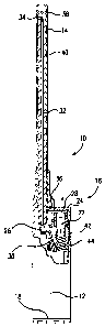
Figures 1-5 generally describe the first embodiment of utility lighter 10 in
accordance to the present invention. Lighter 10 comprises a housing 12, a
conductive
wand 14, and a pocket lighter 16. The pocket lighter 16 is sized and
dimensioned to be
inserted into the housing 12. An end cap 18 is adapted to fit into the back
end of housing 12
to retain pocket lighter 16 inside the housing. Alternatively, the housing may
be formed
from two equal halves.
As illustrated, pocket lighter 16 is substantially a standard piezoelectric
lighter,
which comprises a housing 20 containing a fuel reservoir, a piezoelectric
element 22 and a
push-button 24. As used herein, the term lighter refers to any lighter, which
has at least a
fuel reservoir, a piezoelectric element and a push-button, and is capable of
producing a
flame. The fuel reservoir is in fluid communication with a gas valve 26, which
preferably
includes a valve and a movable jet. Valve 26 is movable between an open
position and a
closed position to selectively release fuel. The piezoelectric element 22 is
preferably
connected to push-button 24, such that when a user pushes the push-button the
piezoelectric
element 22 is compressed to produce an electrical charge. In the pocket
lighter 16, the
electrical charge is conducted to electrode 28 and to valve 26, or a
conductive diffuser
spring attached to valve 26, to generate a spark therebetween. As the push-
button
compresses the piezoelectric element 22, the push-button also acts on biased
pivotal arm 30,
which is operatively connected to valve 26 to lift the valve to selectively
release fuel to be
ignited by the spark generated across the gap between the valve 26 and the
electrode 28.
Pocket lighter 16, as described thus far, is substantially similar to the
lighter illustrated in
the `697 patent and in U.S. patent No. 5,854,530.
As shown in Fig. 2, an elongated fuel conduit 32 is connected to gas valve 26
at one
end to communicate the fuel released from pocket lighter 16 to the front end
of the wand 14.
Conduit 32 can be either rigid or flexible and terminates at a nozzle 34,
which may include
a diffuser spring, at the opposite end. Furthermore, conduit 32 can have any
shape or
configuration as long as it communicates the fuel released from valve 26 to
nozzle 34, and
conducts the electricity from valve 26 or the diffuser spring attached thereto
to nozzle 34.
For example, conduit 32 may be constructed from an electrically conductive
metal or a

CA 02400932 2002-08-21
WO 01/63179 PCT/US01/05538
pliable conductive rubber. Conduit 32 may also comprise a conductive member,
such as a
metal wire, disposed inside an insulated tube. Alternatively, the conductive
member may be
embedded within the wall of the insulated tube. The conductive member may also
be a
portion of the wall of the insulated tube. The conductive member may comprise
a plurality
5 of wires disposed either inside the tube or within the wall of the tube.
Additionally, the
conductive member can also be a mesh or woven wire or a conductive tube
disposed
concentrically with respect to the insulated tube. These shapes and
configurations are
known in the art and are illustrated in EP 222 336 Al publication, among other
references.
Alternatively, an insulated conductive wire may be used, as illustrated in
U.S. patent No.
5,934,895. Of course, the insulated wire can be positioned.inside or outside
of the conduit.
Preferably, the wind guard on the lighter is removed before the conduit is
connected
to the valve. The pocket lighter and the conduit are then inserted into the
housing 12 and
electrically conductive wand 14, as illustrated in Figs. 2-4. As shown in
Figs. 3, 4, 5(a) and
5(b), wand 14 has extension 36 which is disposed within the housing 12.
Electrode 28 of
pocket lighter 16 is sized and dimensioned to maintain sliding contact with
extension 36
when the piezoelectric element is being compressed, such that the electrical
charge from
electrode 28 is conducted through wand 14 to front electrode 38. Preferably,
electrode 28 is
in contact with extension 36 when the electrical charge is generated. On the
other hand, as
discussed above conduit 32 and nozzle 34 are preferably electrically
conductive to
communicate the electrical charge from valve 26 to nozzle 34. The spark
generated
between nozzle 34 and front electrode 38 would ignite the fuel released from
nozzle 34 to
produce a flame.
Preferably, a hollow insulated sleeve 40, as shown in Figs. 3 and 4, is
disposed
between wand 14 and nozzle to prevent the spark from occurring anywhere except
between
nozzle 34 and front electrode 38. Alternatively, as shown in the `895 patent,
the housing 12
may extend to the front end of the lighter and wand 14 can be disposed on the
outside of the
extended portion of the housing. In this case, the extended portion of the
housing
electrically insulated the conductive wand from the conduit 32.
Pocket lighter 16 also preferably comprises a child-resistant mechanism, such
as a
latch 42 disposed between the push-button 24 and housing 20 of the pocket
lighter.
Latch 42 is biased by a spring 44 to an inoperative position, where it
prevents the actuation
of the push-button, as shown in Fig. 3. A user may move latch 42 against the
biasing force

CA 02400932 2009-04-14
6
of spring 44 to an operative position, where actuation of the push-button is
allowed. For the
exemplary lighter 16 illustrated in Fig. 3, movement of latch 42 in the inward
direction, i.e.,
toward the valve 26, place the lighter 16 in the operative position. Further
upward
movement of latch 42, i.e., toward push-button 24, temporarily holds latch 42
in the
operative position. After the user depresses and releases the push-button,
spring 44 biases
the latch 42 back to the inoperative position.
The structure and operation of latch 42 as illustrated herein are fully
described in
U.S. patent Nos. 5,445,518 and 5,584,682.
Other piezoelectric child-resistant
lighters with a child-resistant latch can be used in conjunction with the
utility lighter 10 of
the present invention. For example, the piezoelectric lighters with child-
resistant latch
disclosed in, but not limited to, U.S. patent Nos. 5,531,591, 5,458,482,
5,240,408,
5,145,358, 4,904,180, 5,462,432, 5,788,476, 5,839,892, 4,904,180, and
5,228,849 are usable
in the present invention. Other child-resistant piezoelectric lighters without
a latch, such as
U.S. patent Nos. 5,885,069, 5,854,530, 5,833,448 and others can also be used.
Other
lighters can also be used, as long as it has a piezoelectnc mechanism
actuatable by a push-
button. The push-button may also be a single trigger, or the push-button may
comprise a
gas release member and a separate a spark generating member.
Housing 12 preferably has a first cut-out portion 46 sized and positioned to
allow
the push-button or the push-button andlor latch to expose therethrough for
user
manipulation. Housing 12 preferably has a second cut-out portion 48 sized and
positioned
to allow the latch to expose therethrough. Second cut-out portion 48 is not
required when
utility lighter 10 is used with a latch-less child-resistant piezoelectric
lighter or when the
latch is located on the push-button. Cut-outs 46 and 48 are illustrated herein
to be
proximate to each other. However, cut-outs 46 and 48 can be located anywhere
on housing
12 to accommodate the push-button and/or latch on the various pocket lighters.
The operation of the utility lighter 10 of the present invention is
substantiaily
identical to the operation of the pocket lighter 16 contained therein, i.e.,
the user operates
the utility lighter the same way that the user would operate the pocket
lighter. One of the
advantages of the present invention is that the ignition mechanism and/or the
child-resistant
mechanism of the pocket lighter become the ignition mechanism and/or child-
resistant
mechanism of the utility lighter.

CA 02400932 2002-08-21
WO 01/63179 PCT/US01/05538
7
A second embodiment of the utility lighter is shown in Figs. 6-10, where wand
50 is
shown. Wand 50 has extension 52 which defines a slot 54, as shown in Fig.
10(b).
Electrode 28 of lighter 16 is movably received in slot 54 to maintain
electrical contact
between electrode 28 and wand 50 when push-button compresses piezoelectric
element 22
to generate a spark. A hook 56 is optionally provided.
While it is apparent that the invention herein disclosed is well calculated to
fulfill
the objects above stated, it will be appreciated that numerous modifications
and
embodiments may be devised by those skilled in the art, and it is intended
that the appended
claims cover all such modifications and embodiments as fall within the true
spirit and
scope of the present invention. For example, the lighter 16 is illustrated in
Fig. 2 without a
wind shield, which normally surrounds valve 26. A wind shield may be
incorporated to the
lighter 16 without departing from the present invention. Furthermore, while
one particular
shape of housing 12 is illustrated, it is well within the purview of one of
ordinary skills in
this art to modify the shape of housing 12 to any aesthetically pleasing
shape, as long as the
housing is sized and dimensioned to receive a lighter such as lighter 16.
25

Dessin représentatif
Une figure unique qui représente un dessin illustrant l'invention.
États administratifs

2024-08-01 : Dans le cadre de la transition vers les Brevets de nouvelle génération (BNG), la base de données sur les brevets canadiens (BDBC) contient désormais un Historique d'événement plus détaillé, qui reproduit le Journal des événements de notre nouvelle solution interne.

Veuillez noter que les événements débutant par « Inactive : » se réfèrent à des événements qui ne sont plus utilisés dans notre nouvelle solution interne.

Pour une meilleure compréhension de l'état de la demande ou brevet qui figure sur cette page, la rubrique Mise en garde , et les descriptions de Brevet , Historique d'événement , Taxes périodiques et Historique des paiements devraient être consultées.

Historique d'événement

Description Date
Inactive : Périmé (brevet - nouvelle loi) 2021-02-22
Représentant commun nommé 2019-10-30
Accordé par délivrance 2010-05-11
Inactive : Page couverture publiée 2010-05-10
Inactive : Taxe finale reçue 2010-02-26
Préoctroi 2010-02-26
Un avis d'acceptation est envoyé 2009-09-08
Lettre envoyée 2009-09-08
Un avis d'acceptation est envoyé 2009-09-08
Inactive : Approuvée aux fins d'acceptation (AFA) 2009-08-26
Modification reçue - modification volontaire 2009-04-14
Inactive : Dem. de l'examinateur par.30(2) Règles 2008-10-17
Lettre envoyée 2008-01-28
Inactive : Lettre officielle 2006-05-11
Inactive : Supprimer l'abandon 2006-05-11
Inactive : RE du <Date de RE> retirée 2006-05-11
Lettre envoyée 2006-05-11
Modification reçue - modification volontaire 2006-03-07
Inactive : Abandon.-RE+surtaxe impayées-Corr envoyée 2006-02-21
Exigences pour une requête d'examen - jugée conforme 2006-02-16
Toutes les exigences pour l'examen - jugée conforme 2006-02-16
Modification reçue - modification volontaire 2006-02-16
Inactive : Page couverture publiée 2002-12-30
Inactive : Notice - Entrée phase nat. - Pas de RE 2002-12-20
Lettre envoyée 2002-12-20
Demande reçue - PCT 2002-10-09
Exigences pour l'entrée dans la phase nationale - jugée conforme 2002-08-21
Demande publiée (accessible au public) 2001-08-30

Historique d'abandonnement

Il n'y a pas d'historique d'abandonnement

Taxes périodiques

Le dernier paiement a été reçu le 2010-02-08

Avis : Si le paiement en totalité n'a pas été reçu au plus tard à la date indiquée, une taxe supplémentaire peut être imposée, soit une des taxes suivantes :

  • taxe de rétablissement ;
  • taxe pour paiement en souffrance ; ou
  • taxe additionnelle pour le renversement d'une péremption réputée.

Veuillez vous référer à la page web des taxes sur les brevets de l'OPIC pour voir tous les montants actuels des taxes.

Titulaires au dossier

Les titulaires actuels et antérieures au dossier sont affichés en ordre alphabétique.

Titulaires actuels au dossier
BIC CORPORATION
Titulaires antérieures au dossier
GERALD J. DOIRON
Les propriétaires antérieurs qui ne figurent pas dans la liste des « Propriétaires au dossier » apparaîtront dans d'autres documents au dossier.
Documents

Pour visionner les fichiers sélectionnés, entrer le code reCAPTCHA :


Pour visualiser une image, cliquer sur un lien dans la colonne description du document. Pour télécharger l'image (les images), cliquer l'une ou plusieurs cases à cocher dans la première colonne et ensuite cliquer sur le bouton "Télécharger sélection en format PDF (archive Zip)" ou le bouton "Télécharger sélection (en un fichier PDF fusionné)".

Liste des documents de brevet publiés et non publiés sur la BDBC .

Si vous avez des difficultés à accéder au contenu, veuillez communiquer avec le Centre de services à la clientèle au 1-866-997-1936, ou envoyer un courriel au Centre de service à la clientèle de l'OPIC.


Description du
Document 
Date
(aaaa-mm-jj) 
Nombre de pages   Taille de l'image (Ko) 
Dessin représentatif 2002-08-21 1 12
Page couverture 2002-12-30 1 32
Abrégé 2002-08-21 2 53
Revendications 2002-08-21 10 387
Description 2002-08-21 7 382
Dessins 2002-08-21 5 94
Revendications 2006-03-07 7 230
Revendications 2009-04-14 7 242
Description 2009-04-14 7 377
Dessin représentatif 2009-09-21 1 5
Page couverture 2010-04-15 2 37
Rappel de taxe de maintien due 2002-12-23 1 106
Avis d'entree dans la phase nationale 2002-12-20 1 189
Courtoisie - Certificat d'enregistrement (document(s) connexe(s)) 2002-12-20 1 106
Rappel - requête d'examen 2005-10-24 1 115
Accusé de réception de la requête d'examen 2006-05-11 1 190
Avis du commissaire - Demande jugée acceptable 2009-09-08 1 162
PCT 2002-08-21 3 113
PCT 2001-02-21 5 218
Taxes 2003-02-21 1 35
Taxes 2009-02-23 1 43
Correspondance 2010-02-26 1 42