Note : Les descriptions sont présentées dans la langue officielle dans laquelle elles ont été soumises.
CA 02401161 2002-08-22
WO 01/64365 PCT/USO1/06379
SMART MACHINE TOOL SYSTEM
Background of the Invention
This invention relates generally to methods and apparatus for
gundrilling (deep hold drilling) or cold forming workpieces on gundrilling
machines, heading machines, or thread rolling machines, including
combination machines like bolt making machines.
In thread rolling dies to which the invention relates, workpieces
are transformed into finished screws by a rolling process as the
workpieces pass between a pair of elongated generally planar dies. One
of the dies is stationary, and the other die is displaced relative to the
other to produce a surface material flow on the workpiece to thereby
form a continuous helical thread path on the screw. In the thread rolling
die machines for which the invention has particular applicability, a
shorter die of a pair of dies is held in stationary relationship while the
longer die is moved in a direction generally parallel to a longitudinal
reference plane. The axis of rotation of the body of the workpiece
travels longitudinally as the workpiece rolls between the pair of dies.
The diameter of the finished thread is controlled by the diameter of the
workpiece and the distance between the dies at the finished end of the
stroke. The dies are configured so that as the workpiece rolls across the
dies, the desired threading is formed on the workpiece. Thread rolling
is also accomplished using cylindrical or planetary dies and machines
and this invention is applicable to all known configurations.
To be competitive in the marketplace, manufacturers must
maintain a cost effective manufacturing environment and must be
responsive to customer requests. These two goals can often be in
conflict. For example, costs may be reduced by maintaining low
inventories of raw materials, finished products, and tooling. However,
if such inventories are too low, the manufacturer may be unable to
promptly respond to a customer order. Manufacturers typically strike a
balance where they maintain some minimum inventory of raw materials
CA 02401161 2002-08-22
WO 01/64365 PCT/USO1/06379
2
andlor finished product such that a hypothetical order may be filled
within an acceptable time period. Such manufacturers also monitor their
tooling to ensure that new tooling is received just as the old tooling
reaches the end of its effective lifetime.
Each set of tools has an effective lifetime which is defined by a
maximum number of operating cycles which may be performed before
the accumulated wear precludes further use. There are several factors
which may change the effective lifetime of a tool set. For example, the
rate of tool wear is proportional to the material hardness of the
workpieces, where the rate of die wear increases as the material
hardness increases. Consequently, the effective lifetime of a die set
which is used to form threads on workpieces composed of relatively
hard stainless steel is lower than the effective lifetime of an identical die
set which is used to form threads on workpieces composed of relatively
soft carbon steel.
Effectively monitoring the effective lifetime of tool sets which are
utilized to produce many short production runs and/or which are utilized
to produce components composed of different materials can be
problematic. Although the number of components produced in each run
or of each material may be fairly easily determined, conventional record
keeping systems for tracking the effective lifetime of the tool set are
cumbersome, resulting in errors which can be quite costly to the
manufacturer and supplier.
Summary of the Invention
Briefly stated, the invention in a preferred form is a machine tool
system including a tool for cold forming a workpiece over an operating
cycle. The tool has an electronic device fixedly mounted thereto which
includes means for storing identification data for the tool and operating
data for the tool. The system also includes a sensor device which
senses each operating cycle of the tool and at least one interface device
CA 02401161 2002-08-22
WO 01/64365 PCT/USO1/06379
3
which provides communication between the electronic device and the
sensor device.
Preferably, the electronic device is encased in sealant material
within a recess in an exterior surface of the tool. The electronic device
may have an antenna extending wifihin the sealant material or an
electrical or fiber optic lead extending through the sealant material to the
surface of the tool.
The machine tool system interface device generally includes a
process monitoring system having a key pad, a monitor, and a
microprocessor. The process monitoring system may include a
temperature sensor for measuring the temperature of the tool and/or a
flow detector for monitoring the flow of coolant to the tool. The
interface device also generally includes a portable electronic reader. The
portable electronic reader includes a first data transmission interface for
sending and receiving signals to the electronic device, memory for
storing the signals received from the electronic device, and a second
data transmission interface for transmitting the stored signals to the
process monitoring system. The portable electronic reader may also
includes a display for viewing the signals received from the electronic
device.
The machine tool system provides a means for monitoring the life
cycle of the tool. Each cold forming tool has a lifetime which can be
expressed as the number of operating cycles which can be expected
rom the tool before such tool no longer operates properly or efficiently.
The sensor device senses each operating cycle of the tool and transmits
operating cycle data to the electronic device, where such operating
cycle data is stored. The identification data and the operating cycle data
stored in the electronic device is accessed by the monitoring system or
the portable electronic reader and is used to calculate the number of
operating cycles that the tool has been used. Subtracting the number
of operating cycles that the tool has been used from the expected
CA 02401161 2005-03-30
68355-76
4
number of operating cycles over the lifetime of the tool
provides a measure of the remaining lifetime of the tool.
According to an aspect of the invention, there is
provided a machine tool system comprising: a tool for cold
forming a workpiece over an operating cycle, the tool having
an electronic device fixedly mounted thereto, the electronic
device having means for storing data including
identification data for the tool and operating data for the
tool, the operating data for the tool including tool life
remaining for the tool; a sensor device which senses each
operating cycle of the tool; and at least one interface
device in communication with the electronic device and the
sensor device.
According to another aspect of the invention,
there is provided a method of monitoring the life cycle of a
cold forming tool in a cold forming system, the tool having
an electronic device fixedly mounted thereto, the method
comprising the steps of: storing identification data for
the tool in the electronic device; sensing each operating
cycle of the tool with an operating cycle sensor device and
transmitting operating cycle data from the operating signal
sensor device; receiving and storing the operating cycle
data in the electronic device; determining the expected
number of operating cycles over the lifetime of the tool;
accessing the identification data and the operating cycle
data stored in the electronic device; calculating the
effective number of operating cycles that the tool has been
used from the operating cycle data; subtracting the number
of operating cycles that the tool has been used from the
expected number of operating cycles over the lifetime of the
tool to determine the remaining lifetime of the tool; and
storing the remaining lifetime of the tool in the electronic
device.
CA 02401161 2005-03-30
68355-76
4a
It is an object of the invention to provide a machine tool system
that automatically monitors the tool usage, facilitating determination of
the remaining tool lifetime.
It is also an object of the invention to provide a machine tool
system that facilitates identification and inventory of multiple tools.
Other objects and advantages of the invention will become
apparent from the drawings and specification.
Brief Description of the Drawings
The present invention may be better understood and its numerous
objects and advantages will become apparent to those skilled in the art
by reference to the accompanying drawings in which:
Figure 1 is a schematic diagram of a first embodiment ~of a
machine tool system in accordance with the invention;
Figure 2 is a partly schematic top view of the machine tool of
Figure 1 comprising a short stationary die and a long displaceable die in
a matched position, the stationary die having a recess containing a
microchip;
Figure 3 is a schematic diagram of a second embodiment of a
machine tool system in accordance with the invention;
Figure 4 is a partly schematic top view of the machine tool of
Figure 2 comprising a stationary short die and a displaceable long die in
a matched position, the stationary die having a recess containing a
sensor and/or a microchip and/or a piezo electric power source;
Figure 5 is a schematic view of the hand-held electronic reader of
Figures 1 and 3;
Figures 6a through 6d are a schematic representation of a cold
heading process utilizing a third embodiment of a machine tool system
in accordance with the invention; and
CA 02401161 2002-08-22
WO 01/64365 PCT/USO1/06379
Figure 7 is a perspective view, partly in section, of a gun drilling
machine utilizing a fourth embodiment of a machine tool system in
accordance with the invention.
Detailed Description of the Preferred Embodiment
5 With reference to the drawings, wherein like numerals represent
like parts throughout the figures, a stationary die 10 and a moveable die
12 are employed to roll a thread on a workpiece to produce a finished
screw by a reciprocating flat die method. The reciprocating moveable
die 12 moves relative to the stationary die 10 in the direction of the
arrows 14 in Figures 2 and 4 to define a rolling cycle. As the workpiece
rolls longitudinally between the starting and final ends 16, 18 of the
stationary die 10, a thread is formed on the workpiece.
As illustrated in Figures 2 and 4, the dies 10, 12 each have
opposing faces 20, 22 configured with ridges and grooves which form
the threads and define, for example, the pitch, major diameter, minor
diameter and thread type of the finished screw. The dies 10, 12 during
each rolling cycle cooperatively gradually penetrate the workpiece to
form the finished screw. The dies 10, 12 are configured so that the
least amount of rolling work as possible is done in the dwell section to
maximize the life of the die.
A starter finger (not illustrated) engages the workpiece blank to
ensure that the moving die 12 picks up the blank and starts the rolling
process. For most applications, as the workpiece starts at the starting
end 16, 24 of each die 10, 12, the threads are deep and sharp. In the
dwell sections 26, 28, the threads are flat and shallower. The starting
end threads are sharp for easier penetration as the screw starts to roll
and get progressively wider along the die length until they ultimately
reach width and depth equal to the desired finished thread form. The
dies 10, 12 are aligned .or "matched" to produce the proper optimum
thread continuum. The final die form is termed the dwell section 26, 28
CA 02401161 2002-08-22
WO 01/64365 PCT/USO1/06379
6
and extends along the die 10, 12 for distance long enough to properly
dimension the screw. The thread and tip are fully developed just prior
to parting the dies.
For each rolling cycle there is an associated pressure cycle. As
described above, the sharpness of the threads and the thread width vary
along the length of the dies 10, 12. Consequently, the pressure force
which is exerted on the workpiece by the dies 10, 12 varies as the
workpiece progresses through the rolling cycle. An ideal pressure cycle
may be calculated and compared to the observed pressure cycle of an
operating thread rolling system as a means of monitoring its
performance. For example, the IMPAX/SK 3000 TM process monitoring
system monitors and displays the rolling pressure force over each rolling
cycle of the thread rolling system. The ideal pressure cycle is displayed
simultaneously so that the operator is provided with real-time
information on deviation from optimum system operating conditions.
The IMPAX/SK 3000 TM process monitoring system utilizes a
piezo-electric sensing device mounted in a die adjusting block to sense
the pressure exerted on the workpiece by the dies. Other conventional
thread rolling system process monitoring systems may utilize other
sensors and locate these sensors in the die block, the frame, or the
yoke.
Conventional process monitoring systems may be utilized in
several different ways. A persistent deviation between the measured
pressure cycle and the ideal pressure cycle generally indicates that the
thread rolling system setup is improper. When this occurs, the operator
may adjust the thread rolling system setup to minimize or eliminate such
deviations and thereby optimize the system performance. A deviation
may indicate that a faulty screw was produced during the rolling cycle
in which the deviation was observed. When this occurs, the operafior
may check the output of the thread rolling system to verify the quality
of the product.
CA 02401161 2002-08-22
WO 01/64365 PCT/USO1/06379
7
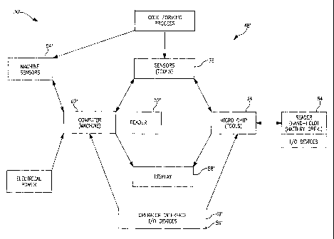
With reference to Figures 1 and 2, a first embodiment 30 of a
machine tool system in accordance with the invention includes a cold
forming tool 32, such as a pair of flat thread rolling dies 10, 12, having
an embedded electronic device such as a microchip 34. Preferably, the
microchip 34 is positioned in a recess 36 in the stationary die 10 and is
mounted within the recess 36 by a sealant material 38, such as potting
compound or epoxy, which seals the recess 36 against infiltration by
particulate matter and liquids. An antenna 40 extending from the
microchip 34 may also be disposed within the sealant material 38.
Alternatively, an electrical or fiber optic lead 42 may extend from the
microchip 34, through the sealant material 38, to at least the surface of
the stationary die 10.
The microchip 34 includes at least a memory portion 44 and a
data transmission portion 46. The memory portion 44 has sufficient
storage capacity to store tool identification and design data which does
not change over the lifetime of the tool and tool operating data which
is updated as the tool is used in the manufacturing process. Permanent
tool data for a thread rolling die set may include the cusfiomer part
number, the manufacturer part number, manufacturing information, set-
up information such as an optimum rolling force curve, and the effective
lifetime expressed as a number of rolling cycles. Operating data for a
thread rolling die set 10, 12 may include the date/time of each set-up,
the dateltime of each run, the number of rolling cycles in each run, the
number of set-up adjustments in each run, abnormal force incidents,
wear pattern documentation by run, and the tool life remaining
expressed as a number of rolling cycles. The microchip 34 stores the
permanent data and the operating data and communicates this data
when queried by an electronic reader. The data transmission portion 46
includes all circuit components and/or software that is required to
transmit and receive the operating data. It should be appreciated that
any electronic device having at least the memory and data transmission
CA 02401161 2002-08-22
WO 01/64365 PCT/USO1/06379
8
portions 44, 46 described above and which is small enough and rugged
enough to be embedded on a cold forming tool 32 may be used in the
present invention.
The cold forming machine 48 in which the cold forming tool 32
is mounted includes a process monitoring system 50 having an
electronic reader 52, which communicates with the microchip 34
embedded in the cold forming tool 32. Such communication may be by
microwave, Rf, infrared, or other common radiation of the
electromagnetic spectrum. The process monitoring system 50 also
includes sensors 54 for detecting various operating parameters of the
cold forming toot 32. The sensors 54 may include a sensor, such as a
piezo electric sensor capable of sensing the pressure cycle, for detecting
operation of the cold forming tool, a temperature sensor for measuring
the temperature of the cold forming tool, or a flow detector for
monitoring coolant flow to the cold forming tool. The process
monitoring system 50 may also include a key pad 56 for inputting data,
a monitor 58 for displaying process information, such as the pressure
cycle and a data output 60 to a master scheduler system or a machine
control system. The process monitoring system sensors 54 and/or the
process monitoring system key pad 56 are utilized to input all the
parameters which are recorded in the microchip 34. A microprocessor
62 in the process monitoring system 50 performs any calculations
which are necessary to convert the input signals or transform the
sensed or inputted data into the form required for storage in the
microchip 34. For example, microprocessor 62 calculates the remaining
effective lifetime of the cold forming tool 32 based on the output of the
sensor 54 which detects operation of the cold forming tool 32 and the
expected life data and prior use data stored in microchip 34.
Preferably, the data/query signal received by the data
transmission portion 46 of the microchip 34 provides the power required
by the microchip 34 to record the data or respond to the query and
CA 02401161 2002-08-22
WO 01/64365 PCT/USO1/06379
9
therefore an external power source is not required. If the data/query
signal does not provide sufficient power, an external power source may
be used. A battery mounted in the recess 36 may be used as the
external power source. Machine generated vibration power may be
utilized as well. Alternatively, a data/power connection may be provided
between the process monitoring system 50 and microchip via electrical
lead 42. If an external power source is utilized, the microchip 34 may
be used to perform more power intensive functions. For example, the
calculations performed by microprocessor 62 could be performed by
microchip 34.
With reference to Figure 5, the machine tool system also includes
a portable, hand-held electronic reader 64. The hand-held electronic
reader 64 includes a communications portion 66, comprising the circuit
components and/or software which are required to send and receive
data and query signals, a data transmission interface 68 for sending and
receiving signals to microchip 34, and a data transmission interface 70
for transmitting the stored data to the central control system or some
other central monitoring system. The hand-held electronic reader 64
also includes memory 72 for storing the data received in response to the
query and may include a display 74 for viewing the data received from
microchip 34.
The hand-held electronic reader 64 provides flexibility to the
subject machine tool system 30, 30'. For example, if the display 58 of
the process monitoring system 50 is at a location which is remote from
the cold forming tool 32, the hand-held electronic reader 64 allows the
operator to query and view the stored data while he is at the cold
forming tool 32.
In addition to the cold forming tools 32 which are in use at any
moment in time in the cold forming machines 48, most manufacturers
also have a tool crib which contains tools 32 which are not actively in
use. When the production run of a first type of screw is completed, the
CA 02401161 2002-08-22
WO 01/64365 PCT/USO1/06379
first die set 10, 12 (which had been used to produce the first type of
screw) is removed from the cold forming machine, a second die set 10,
12 designed for producing the second type of screw is removed from
the tool crib and mounted in the cold forming machine 48, and the cold
5 forming machine 48 commences the production run of the second type
of screw. If the first die set 10, 12 has not reached the end of its
effective lifetime, it is placed in the tool crib for use in the next
production run of the first type of screw. If the first die set 10, 12 has
reached the end of its effective lifetime, it is discarded, a new first die
10 set 10, 12 is purchased and placed in the tool crib. Therefore, the tool
crib generally contains new die sets and used die sets. With good
administrative controls, a manufacturer can easily know which cold
forming tools 32 are installed in the cold forming machines 48 and
which cold forming tools 32 are stored in the tool crib. However, it is
more difficult for the manufacturer to know which cold forming tools 32
are new and which are used and much more difficult for the
manufacturer to know how many more parts may be produced by any
one of the used cold forming tools 32.
The hand-held electronic reader 64 and imbedded microchip 34
provide a means for easily conducting and maintaining an accurate
inventory of the manufacturers' cold forming tools 32. More
importantly, an inventory conducted with the subject the hand-held
electronic reader 64 and imbedded microchip 34 includes easily
accessible and up to the minute information on the operating history of
each of the cold forming tools 32 and the tool remaining life. To
conduct the inventory, the user merely passes the hand-held electronic
reader 64 by each cold forming tool 32. During each pass, the reader
64 queries the tool 32, the tool 32 transmits data stored in the
microchip 34, and the transmitted data is stored in memory 72.
Depending on the capacity of the memory 72, the amount of data which
is received from each tool 32, and the number of tools 32 which must
CA 02401161 2002-08-22
WO 01/64365 PCT/USO1/06379
11
be inventoried, the stored data is downloaded to the central computer
periodically during the inventory or at the end of the inventory, and the
central computer compiles an inventory list. The data query may be
customized depending on the needs of a particular inventory. It should
be appreciated that the accuracy and ease of use of this method of
inventory is dependent on the microchip 34 which is embedded in and
inseparable from each cold forming tool 32.
The embodiment 30' illustrated in Figures 3 and 4 is very similar
to the first embodiment 30 with the primary exception that a sensing
device 76, such as a piezo electric device, is mounted in the recess 36
and in communication with the microchip 34. Consequently, the
sensing device signal may be received directly by the microchip 34
instead of by way of the microprocessor 62' in the process monitoring
system. Preferably, the sensing device signal provides the power
required by the microchip 34 to record the data. Alternatively, an
external power source such as a battery or an electrical connection with
the microprocessor may be used. Similar to the first embodiment, the
microchip 34 may perform any required calculations and data conversion
if an external power source is utilized. Otherwise, the process
monitoring system microprocessor 62' performs the required
calculations and data conversion. The process monitoring system
includes an electronic reader 52', additional sensors, a key pad 56', a
monitor 58', and a data output 60' to a master scheduler system or a
machine control system.
Figures 6a through 6d show the basic sequence of actions in a
standard type solid die, double stroke heading machine. In Figure 6a,
wire 78 is shown being fed through the cut off die 80 until it reaches
fihe wire stop 82. By adjusting the location of this stop 82, the operator
determines the length of the blank 86.
In Figure 6b, the cutoff knife 84 has already cut the blank 86
from the coil and carried it (the blank) to the heading die 88. The knife
CA 02401161 2002-08-22
WO 01/64365 PCT/USO1/06379
12
stroke is set to stop when the blank 86 is centered on the heading die
88.
In Figure 6c, the 'first punch 90 comes forward for the first blow.
The first and second punches 90, 92 are both carried on the ram or gate
94 (both terms are commonly used). As the first punch 90 begins its
forward stroke, it pushes the blank 86 into the heading die 88, right up
against the knockout pin 96 (if no extrusion is being done). At this
point the blank 86 is subjected to the full force of the first punch 90,
and begins to flow into its new shape. As the first blow is completed,
the extrusion, if any, is done, and the head has been upset into the cone
shape, ready for final shaping.
With reference to Figure 6d, the cam-operated mechanism shifts
the punches 90, 92 after the first blow, so that the second punch 92 is
aligned with the heading die 88. The gaffe 94 comes forward again, the
' second or finish blow, is struck, and the gate 94 withdraws. As it
withdraws, the punches 90, 92 are now shifted so that the first, or
cone punch 90, is again in position for the new blank. Meanwhile, as
the gate 94 is withdrawing, the knockout pin 96 comes forward all the
way to the face of the die 88, forcing the finished part 98 out ahead of
it. As the gate 94 reaches its fully withdrawn position, the finished part
98 is ejected and falls into a collection bin 100. The cutoff knife 84 is
already starting to move a new blank into position, ready to begin the
cycle al( over again.
As shown in Figures 6c and 6d, a sensor 102, 102' and a
microchip 104, 104' are mounted in a recess in each of the gate 94 and
heading die 88. The sensors 102, 102' detect each operation of the
cold heading tool and transmit a signal to a process monitoring system
for use by the system and for storage in the microchip 104, 104'.
With reference to Figure 7, gundrilling is a metal removal process
utilizing a drilling machine 108, a high pressure coolant system 1 10, and
a single or a two flute gundrill 112. The gundrilling process is a
CA 02401161 2002-08-22
WO 01/64365 PCT/USO1/06379
13
controlled operation which offers size, location, finish, and straightness
accuracy where critical tolerances are important. Added benefits are
scrap reduction, burr-free holes, bottom forming, and blind holes, as well
as entry with surfaces other than 90 degrees. Repeatability makes this
application feasible on numerically controlled equipment.
In addition to dedicated gundrilling machines 108, gundrills 1 12
and coolant systems 110 are easily integrated with CNC machining
centers, lathes, and milling machines, providing users with all the
benefits of the process for a relatively small investment. Incorporating
gundrills 1 12 on other types of machinery often requires a short ( 1 to
2 diameters deep) starter hole to be used in place of the gundrilling
machine's starter bushing 1 16. The gundrill tip 1 14 is then fed Into the
predrilled hole before engaging the spindle.
The gundrill 1 12 is a simple, basic tool with three essential parts:
the tip 1 14, the shank 1 18, and the driver 120. These parts are brazed
together into one correctly aligned unit.
The tip 1 14 is the most critical of the three elements. The tip
1 14 cuts the hole and maintains precision as it pilots the drill through
the part, producing precision holes in one pass. The point or nosegrind
has two basic angles that may be varied for optimum results depending
on the material to be drilled. These angles must balance the cutting
forces, distributing them to the tip's bearing pads to keep the drill
concentric. The tip 1 14 is slightly larger in diameter fihan the shank,
thus enabling the shank 1 18 to rotate freely without contacting the hole
wall. Through the tip 114 is an oil hole which lines up with the shank's
oil channel to facilitate correct flow of coolant at high pressures to the
cutting edge.
As shown in Figure 7, a sensor 122 and a microchip 124 are
mounted in a recess 126 in the gundrill 1 12. The sensor 122 detects
each operation of the gundrill 1 12 and transmits a signal to a process
CA 02401161 2002-08-22
WO 01/64365 PCT/USO1/06379
14
monitoring system for use by the system and for storage in the
microchip 124.
It should be appreciated that the heading, threading, and
gundrilling machine tools described above may include sensors, other
than the load sensors, for monitoring additional system parameters. For
example, sensors 128, 130, 132 may also be located in other
components of the gundrilling system, as shown in Figure 7. Sensors
128 in the coolant system 1 10 may be provided to sense coolant flow
and/or temperature.
While preferred embodiments have been shown and described,
various modifications and substitutions may be made thereto without
departing from the spirit and scope of the invention. Accordingly, ifi is
to be understood that the present invention has been described by way
of illustration and not limitation.