Note : Les descriptions sont présentées dans la langue officielle dans laquelle elles ont été soumises.
' PCT/13P 01/01248 CA 02401202 2002-08-23
, , , 1
Ac~4ENDMENTS UNDER ARTICL$ 34
Sealing System
The invention relates to a sealing system in accordance with the
features set forth in the preamble of Claim 1.
German Publication DE 503 769 C discloses a pipe connection with
such a sealing system, which comprises two radially outer or radially
inner sealing rings and a connecting piece that forms a partition and
is arranged therebetween. The partition is disposed in a chamber of the
two components to be joined and is configured as a double T-shaped ring
with lateral flanges. When the two components are joined, the lateral
flanges of the partition are bent and the sealing rings are pressed
into the chamber. In other respects, the partition keeps its shape. In
the event of fire, the two sealing rings, which are made of a soft
sealing material, can be damaged or destroyed so that the seal is
subsequently no longer guaranteed.
Furthermore, US Patent 3,869,132 A discloses a sealing system
designed to be fire resistant, which comprises a first metallic sealing
ring and a radially inner second sealing ring that is made of an
elastomer. The first metallic sealing ring is especially C-shaped and
fits radially outwardly against a chamber wall. If the second sealing
ring is destroyed, the seal is formed exclusively by the first metallic
sealing ring. Due to unevenness, scratches, or the like in the
superimposed surfaces of the first sealing ring and the chamber walls,
there is a risk of substantial leaks.
Also known are fire resistant sealing systems that are configured
as metal-graphite seals. To satisfy the requirement that the first
sealing ring, which is at least partially made of graphite or a
comparable high-temperature sealing material, cannot come into contact
with the fluid flowing through the components,
AMENDED SHEET 3/26/2002
Time received: March 26 1:20 p.m.
~ WO 01/63152 cA 02401202 2002-08-23 PCT/$PO1/01248
2
a second seal is provided on the fluid side. This requires a
considerable amount of space. Furthermore, additional metal seals may
be provided, which are costly and have a relatively high leakage rate.
Based thereon, it is the object of the invention further to
develop a sealing system of the initially described type in such a way
as to ensure a functionally reliable seal at low production and/or
installation costs. The sealing system should require little space and
no additional parts or process steps. In addition, the sealing system
should satisfy the requirements of fire safety and should be resistant
to the fluid flowing through the components, particularly resistant to
chemicals.
This object is attained by the features set forth in Claim 1.
The sealing system according to the invention has a simple
structure and is distinguished by its high functional reliability. It
requires very little space. A second fluid-side soft sealing ring is
assigned to the first sealing ring. A partition, particularly in the
form of a metal ring, is arranged between these sealing rings. This
creates a sandwich type sealing element, which is preferably configured
as a flat seal and is ready to be installed in the chamber. The
partition is clamped between the components when they are joined and is
deformed in such a way that the volume of the first sealing ring is
reduced and the first sealing ring is thereby compressed and chambered.
The metal ring prestresses the first sealing ring, particularly in
radial direction. This prestress is maintained even if the second
sealing ring is damaged or destroyed, particularly as a consequence of
fire, so that a reliable outward seal is ensured. The partition is
substantially more rigid than the first sealing ring, which is thus
always functionally reliably supported by the partition, independent of
the second soft sealing ring, and is prestressed and/or compressed as
required in the partial chamber, which is separated by the partition.
The partition or the metal ring is deformed during installation because
the contact surfaces of the partition rest against both a chamber wall
of the one component and a chamber wall of the other component, and the
distance between these chamber walls is reduced when the seal is
~, WO 01/63152 cA 02401202 2002-08-23 PCT/BPO1/01248
3
installed and/or when the components are joined. The partition is
advantageously preformed in such a way that the volume of the chamber
part containing the first sealing ring is also changed by the partition
and preferably reduced to compress the first sealing ring. The sealing
element according to the invention performs a dual function, namely to
provide a seal that is resistant to fire and resistant to chemicals. It
requires very little space and is a cost-effective solution without
requiring any additional parts or process steps.
The soft second sealing ring, which is made, in particular, of
PTFE, an elastomer or a similar material, is arranged on the other side
of the partition. The sealing element according to the invention is
thus configured as a prefabricated component and is arranged in one and
the same chamber, which is formed by projections, tongue and groove
arrangements, or the like of the two components. In relation to the
first sealing ring and the partition, the second soft-elastic sealing
ring is arranged on the fluid side and thus prevents the fluid from
coming into contact with the partition or the first sealing ring. If
the first sealing ring [sic] is destroyed by fire or other external
influences, the inventive annular partition, which is clamped between
the components, nevertheless maintains the chambering of the first
sealing ring and thereby also ensures a reliable outward seal. In
normal operation, the second sealing ring, which is made of PTFE or
some other soft sealing material, prevents the first sealing ring,
which is made of graphite or some other high-temperature sealing
material, from coming into contact with the fluid. The three rings
advantageously form a prefabricated and/or integral sealing element,
which is inserted into a single chamber for installation. The annular
partition located between the first and second sealing ring is clamped
therebetween when the components are assembled and joined and is
further deformed in such a way that the first sealing ring is
compressed and at the same time completely chambered. To increase its
rigidity, the partition is preferably provided with a rib, which
projects particularly into the partial chamber of the first sealing
ring. This rib is preferably formed by the deformation of the
partition, particularly by buckling and/or compression during
installation. The rib forms an integral part of the partition, which
.~ , WO 01/63152 cA 02401202 2002-08-23 PCT/EPO1/01248
4
has preferably a substantially uniform thickness and/or is
approximately triangularly deformed in the direction of the
longitudinal axis.
In the sealing system according to the invention, the
aforementioned three rings are advantageously arranged coaxially to one
another, with the first sealing ring forming the outer ring and the
second sealing ring the inner ring, between which the advantageously
preformed partition is arranged. The axial width of the second or inner
sealing ring is advantageously smaller than the axial width of the
metal ring and/or the first or outer sealing ring. During installation,
the distance between the axially opposite chamber walls of the two
components is reduced and after installation is complete the two
sealing rings are firmly pressed into the chamber under prestress. The
partition with the aforementioned contact surfaces fits tightly and/or
under prestress against the chamber walls, which are axially opposite
and/or in substantially radial planes.
Further developments and special embodiments of the invention
will now be described with reference to an exemplary embodiment. The
sealing system is preferably used in valves, cocks or gates, and the
aforementioned components are housing parts thereof. It should be noted
that the inventive sealing system can be used for components of various
types, e.g., pipe parts, housing parts, etc.
A special embodiment of the invention configured as a ball valve
will now be described in greater detail, by way of example, which shall
not be construed as a limitation. In the drawing
Figure 1 is an axial longitudinal section through a ball valve with
the inventive sealing system between the two components,
which are configured as housing parts,
Figure 2 is an enlarged detail of Figure 1,
Figure 3 is a partial axial section through the inventive integral
sealing element prior to installation or prior to clamping
between the components,
yV0 01/63152 CA 02401202 2002-08-23 PCT/SPO1/01248
Figure 4 shows this sealing element after installation.
According to Figure 1, two components 2, 4 by way of example are
configured as the housing parts of a ball valve enclosing an interior
space 5 through which a fluid flows. They are joined by means of a
flange connection 6. A plurality of screws 10 is distributed in known
manner along the circumference, i.e., relative to a longitudinal axis
8. In housing part 4, a valve ball 12 with a through opening 14 is
supported by means of a stem 16 so as to be rotatable about an axis 18.
To actuate the ball valve, a lever 19 is non-rotatably coupled with
stem 16. By turning this lever 90°, the valve ball 12 can be rotated
out of its depicted open position into its locked position in which the
axis of the through opening 14 is disposed perpendicularly to
longitudinal axis e. In the junction area 20 of the two housing or
component parts 2, 4, an annular sealing element 22 is arranged in a
chamber between the two component parts 2, 4.
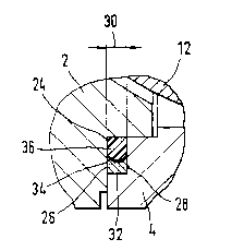
According to Figure 2, chamber 24 is formed on the one hand by an
annular groove 24 made in component 4 and on the other hand by an
annular collar made in component 2. Chamber 24 has a substantially
rectangular cross section. There are two chamber walls 26, 28, which
are diametrically and axially spaced apart. Chamber 24 is furthermore
bounded by two diametrically and radially spaced apart chamber walls of
components 2 or 4. When components 2, 4 are assembled, chamber walls
26, 28 are spaced apart at an axial distance 30. The inventive sealing
element, which is configured as a flat sandwich type seal, is arranged
in chamber 24. It comprises a first sealing ring 32, a partition
configured as a metal ring 34, and a second sealing ring 36. The first
sealing ring 32 is particularly made of graphite or a comparable high-
temperature sealing material, while the second sealing ring 36 is a
soft seal particularly made of PTFE, an elastomer or some other soft
sealing material. The second sealing ring 36 is arranged in front of
metal ring 34 and/or the first sealing ring 32 as seen in the direction
of ball 12, which is associated with interior space 5 through which the
fluid of the ball valve flows. Consequently, the second sealing ring 36
protects sealing ring 32 as well as partition 34 or the metal ring
against the influences of the fluid. In this particular embodiment, the
.~ WO 01/63152 CA 02401202 2002-08-23 PCT/SPOl/01248
6
first sealing ring 32, metal ring 34 and second sealing ring 36 are
arranged coaxially, i.e., relative to the longitudinal axis 8 of the
two components 2, 4 or the ball valve. The first sealing ring 32 forms
an outer ring and the second sealing ring 36 an inner ring, with the
metal ring 34 arranged therebetween.
Figure 3 shows the sealing element prior to installation or prior
to being set into the aforementioned chamber between the components.
Compared to the axial width 38 of the first sealing ring 32, the axial
width 40 of the inner ring or second sealing ring 36 is smaller by a
predefined amount. The radial thickness of the metal ring 34 is
substantially constant over the axial length. The metal ring 34 is
preformed in V-shape and in particular has a radially outward directed
rib 43 with a point or a rounding 42, which is facing the first sealing
ring 32. Furthermore, metal ring 34 comprises diametrically arranged
contact surfaces 44, 46 that are axially spaced apart from one another
and fit against the aforementioned axially opposite chamber walls of
the two components. For installation, the inventive preformed integral
sealing element, which is ready to be installed, is inserted into the
chamber. As the sealing element is installed or as the two components
are joined, axial forces are acting on metal ring 34 in the direction
of arrows 48, 50. This causes further deformation of metal ring 34 such
that the point or rounding 42 and the axially adjacent partial areas of
metal ring 34 on either side are deformed radially outwardly. Thus, the
first sealing ring 32 is prestressed or compressed during installation
and, in addition, an inventive chambering is effected by means of metal
ring 34. During installation, the aforementioned chamber walls are
moved toward one another far enough so that the soft second sealing
ring 36 also finally fits against the aforementioned axially opposite
chamber walls, advantageously under prestress, so as to form a seal. It
should be expressly noted that the chamber is dimensioned in such a way
that after installation is complete, the two sealing rings 32, 36
advantageously fit also in radial direction against the radially
opposite chamber walls.
Figure 4 shows the sealing element after installation is
complete. Compared to Figure 3, the deformation of the cross-
WO 01/63152 cA 02401202 2002-08-23 PCT/SP01/01248
7
sectionally V-shaped metal ring 34 is clearly visible here. It may be
seen that the metal ring 34 with its contact surfaces 44, 46 fits
prestressed and tightly against the axially opposite chamber walls. The
axial width of the sealing element corresponds to distance 30 of the
aforementioned chamber walls as described with reference to Figure 2.
Metal ring 34 forms the partition for the first sealing ring 32 in the
direction of the fluid side such that if the second sealing ring 36 is
damaged or destroyed, particularly due to fire, the chambering of the
first sealing ring 32 remains unchanged and a reliable outward seal is
consequently ensured.
WO 01/63152 cA 02401202 2002-08-23 PCT/SPOl/01248
' 8
Reference Numerals
2, 4 component, housing
part
interior space
6 flange connection
8 longitudinal axis
screw
12 valve ball
14 through-bore
16 stem
18 axis of rotation
19 lever
junction area
22 sealing element
24 chamber
26, 28 chamber wall
distance between 26 and 28
32 first sealing ring / outer
ring
34 metal ring
36 second sealing ring / inner
ring
38 width of 32
width of 36
42 point / rounding of 34
43 rib
44, 46 contact surface of 34
48, 50 arrow