Note : Les descriptions sont présentées dans la langue officielle dans laquelle elles ont été soumises.
CA 02402638 2002-09-09
WO 01/69289 PCT/USO1/07668
METHODS FOR PRODUCING OPTICAL FIBER
BY FOCUSING HIGH VISCOSITY LIQUID
FIELD OF THE INVENTION
This application generally relates to the field of producing elongated strands
from highly viscous liquid materials, and more particularly to the creation of
optical fibers
from molten glass using focused fluid technology.
BACKGROUND OF THE INVENTION
Optical fibers are thin strands of materials, such as glass or polymeric
compounds, capable of transmitting an optical signal containing a large amount
of
information over long distances with very low loss. (See U.S. Patents
6,128,429; 6,098,428;
6,057,034 and publications and patents cited in each of these patents) Optical
communication systems based on glass optical fibers allow communication
signals to be
transmitted over long distances with low attention and at extremely high data
rates, or band
width capacity. This capability arises form the propagation of a single
optical signal mode in
the low loss windows of glass located at the near-infrared wavelengths. Since
the
introduction of erbium doped fiber amplifier (EDFA), the last decade has
witnessed the
emergence of the glass optical fiber as the standard data transmission medium
for wide area
networks (WANs).
Conventional optical fibers are typically manufactured by constructing an
optical fiber preform of appropriate composition and drawing a fiber from the
preform. (See
U.S. Patent 6,053,012 and patents and publications cited therein) A typical
preform is a
concentric glass rod having a length of about one meter and an outer diameter
of 20-200
mm. The inner core of the rod is a high purity, low loss glass such as
germanium silicate
glass having a diameter of about 1-5 mm. The concentric outer cylinder,
referred to as
cladding, is a layer of glass with a lower index of refraction than the inner
core.
In the conventional manufacture of an optical fiber, the preform is lowered
into the insulated susceptor of an RF induction fizrnace where it is heated to
a high drawing
temperature. (See U.S. Patents 5,741,384; 5,698,124 and patents and
publications cited in
each) A strand of glass is pulled from the heated portion of the preform at a
tension and rate
to draw a fiber of desired diameter. One of the primary difficulties with this
conventional
CA 02402638 2002-09-09
WO 01/69289 PCT/USO1/07668
process is contamination of the fiber from the materials of the induction
fizrnace. Even very
small particulates from the insulation or susceptor can produce localized weak
points in the
fiber which will ultimately result in breakage or other forms of failure. U.
S. Pat. No.
4,440,556 describes an early attempt to solve this contamination problem by
directing a
plasma torch axially onto a preform and drawing a fiber axially through a
central passage in
the torch. The difficulty with this approach is that to reach the central
passage, the drawn
fiber must pass through the plasma fireball. But plasma shapes are notoriously
difficult to
control, and even minor fluctuations in shape can subject the delicate drawn
fiber to severe
temperature fluctuations.
Another difficulty arises from the use of increasingly larger diameter
preforms. With larger diameter preforms it is very difficult to generate a
sufficiently large
plasma fireball to cover the entire diameter of the preform. The result is non-
uniform heating
in the drawing region. Similar methods, such as the method described in U. S.
Patent No.
5,672,192, address some of the problems inherent in these methods, but still
requires the use
1 S of a plasma torch and thus has many of the limitations inherent to this
use.
The success of the single-mode glass optical fiber in communication
backbones has given rise to the concept of optical networking. These networks
serve to
integrate data streams over all optical systems as communication signals make
their way
from WANs down to smaller local area networks (LANs) and eventually to the end
user by
fiber to the desktop. The increased use of optical networks, based in large
part on the recent
explosion of the Internet and use of the World Wide Web, has demanded vastly
higher
bandwidth performance in short- and medium-based applications.
There is thus a need in the art for improved methods of producing glass
optical fibers to meet the growing demands of consumer use. In addition, there
is a growing
demand for better optical fibers, both single mode and multimode optical
fibers.
SUMMARY OF THE INVENTION
The invention is directed to the production of optical fibers using flow
physics. The present methods provide for the focused extrusion of a highly
viscous material
such as molten germanium silicate glass, either directly from a molten liquid
or from a
perform, using a fluid (e.g. a heated gas or liquid) that surrounds and
focuses the high
viscosity liquid stream or preform, resulting in an evenly shaped, elongated
fiber. The
2
CA 02402638 2002-09-09
WO 01/69289 PCT/USO1/07668
invention also provides methods and devices for the manufacture of optical
performs, which
can then be drawn using conventional technology or using the drawing methods
disclosed
herein.
A flow physics methodology which is applied to low viscosity fluids is
described in publications such as U. S. Patent 6,116, 516 issued September 12,
2000;
6,187,214 issued September 13, 2001; 6,197,835 issued March 6, 2001; and
6,196,525
issued March 6, 2001. However, these disclosures relate to the extrusion of
low viscosity
fluids. What is mean by low viscosity fluid is that the fluid has a Reynolds
number which is
relatively high, for example a number about 10 or more. The extrusion of low
viscosity
fluids is carried out under conditions using forces which are not dominated by
the viscosity
of the fluid but rather dominated by the mass of the fluid or its density. By
analogy, the
engine of car moves the car forward using the power of the engine largely to
have an effect
on the mass of the car and, to a lesser extent, in order to overcome the
frictional resistances
existing between various components. However, if the frictional forces are
substantially
increased such as by applying the emergency brake of the car then there
frictional forces
become the dominant forces which must be overcome in order to move the car
forward. In
this analogy the frictional forces relate to the viscosity of the fluid.
The disclosure provided here is directed towards methodology which
describes creating streams and fibers from high viscosity fluids. The term
"high viscosity
fluid" is intended to encompass fluids wherein the Reynolds number is
relatively small,
specifically a Reynolds number of about 1 or less. More particularly, the
Reynolds number
in a very high viscosity fluid is less than about 0.1. With high viscosity
fluids, as with the
car with the emergency brake on, the viscosity of the fluid becomes a
dominating factor in
terms of what must be overcome by the forces applied in order to move the
fluid forward just
as the frictional resistance created by the emergency brake becomes the
dominating factor
which the car engine must overcome in order to move the car forward.
A section entitled "mathematical formulation" is included below. This
section includes equations which will be understood by those skilled in the
art upon reading
this disclosure as applicable to the manufacturing of streams and fibers from
high viscosity
fluids such as the high viscosity fluid of molten silica glass with a high
viscosity fluid of a
heated glass preform used in creating fibers which are used to optically
transmit information.
CA 02402638 2002-09-09
WO 01/69289 PCT/USO1/07668
In a first embodiment, elongated fibers such as optical fibers are produced
directly from a highly viscous liquid, e.g., molten silicate glass, by
subjecting a stream of the
viscous liquid to a surrounding, focusing fluid. This allows fibers to be
generated without
the need for producing a perform, and can also allow the extrusion of multiple
fibers
simultaneously. This extrusion is particularly advantageous in that the fiber
stream does not
contact the surface of the orifice upon extrusion of the fiber from the
devices of the invention
because the extruded fiber is completely surrounded by and focused with the
focusing fluid
which may be a gas. This makes it possible to reduce contamination of the
fiber and
essentially prevents clogging of the device orifice. Elongated fibers produced
can have any
desired diameter but are preferably 200 microns or less in diameter and may be
from 1
micron to 50 microns in diameter.
In another embodiment, optical fiber preforms are reduced in diameter and
increased in length using the focusing properties of a surrounding fluid. The
optical fiber
precursors (i.e. the preforms) are heated to a temperature that allows the
preform material to
maintain the basic structural elements of the preforms while allowing the
preform to become
ductile or specifically to be stretched to the desired length and lateral
dimensions, i.e. a
temperature which renders the optical fiber precursor ductile and allows the
fiber to maintain
the lateral relationship of the preform. The focusing process may be repeated
to provide the
desired diameter and/or length of the fiber, a focusing fluid and the narrowed
structure can
be fixrther narrowed by repeated exposure to focusing fluid.
In another embodiment hollow fibers are produced. The hollow fibers are
extruded from a source comprised of two concentrically positioned tubes. The
center tube
extrudes a gas such as air or a highly pure inert gas and the surrounding
concentric tube
extrudes molten silicate glass. The extruded silicate glass forms a hollow
tube and is
focused to a jet by the surrounding flow of gas in a pressure chamber.
Multiple hollow
fibers may be extruded simultaneously and joined together before solidifying,
e.g. to form a
photonic band gap structure.
An advantage of the invention is that the focusing pressure from the
surrounding focusing fluid provides pressure distribution on the viscous
liquid extruded or
the preform and the pressure distribution can be calculated mathematically to
show that it
suppresses instability before any fiber drawing viscosity thereby indicating a
theoretically
unlimited increase in productivity.
4
CA 02402638 2002-09-09
WO 01/69289 PCT/USO1/07668
Another advantage of the invention is that shear stress on the fiber produced
from the extruded viscous material can be reduced to a minimum thereby
allowing the
controlled production of complex fiber structures including hollow fibers
which can be
combined to produce any desired configuration of photonic bandgap structures.
Yet another advantage of the invention is that gas temperature distribution
along the nozzle is very rapidly transferred to the drawn fiber material
thereby providing a
means for a simple and accelerated control of the fiber temperature profile
and oi~ering a
robust and simple manner of controlling the fiber quenching process and
enhancement of
fiber quality.
An advantage of the invention is that the optical fibers formed are uniform in
size and shape along this length and are created with a relatively small
amount of energy.
Another advantage of the invention is that it allows multiple fiber extrusions
to take place simultaneously, thus allowing the fibers to be extruded as a
bundle.
Yet another advantage of the invention is that the fibers can be extruded as a
coated fiber using concentric needles in the devices of the invention.
Yet another advantage of the invention is that optical fibers can be created
without contamination, resulting in optical fibers without localized weak
points in the fiber
caused by such contamination.
Yet another advantage of the invention is that fiber forming and stability
using the production methods of the invention can be enhanced using an
appropriate external
pressure distribution.
Yet another advantage of the invention is that fiber stress can be
dramatically
reduced upon extrusion of the devices of the invention, as glass to solid
contact is avoided
due to the extrusion of the glass surrounded by the focusing gas or liquid.
Yet another advantage of the invention is that the device of the invention
will
have minimal contamination and/or clogging from the extrusion of the fiber, as
the exit
orifice never touches the fluid or perform.
Yet another advantage is that fiber quality is enhances by rapid fiber
quenching owing to the coflowing gas expansion.
Yet another advantage of the invention is that complex fiber concentric
structures can be formed by the dramatic reduction of radial viscous stresses
of the present
methods as compared to classic techniques.
CA 02402638 2002-09-09
WO 01/69289 PCT/USO1/07668
Yet another advantage of the present invention is that when preforms are used
they are not subject to fluctuations in shape based on the focusing procedure,
and thus the
drawn fibers are not subject to severe temperature fluctuations as with the
use of plasma
fireballs.
Yet another advantage is that the extrusion methods can be designed to create
fibers with discrete fi.~nctional elements based on the orientation of
extrusion. This allows
the production of specialized fiber structures, such as photonic bandgap
structures, in
conventional length fibers.
Yet another advantage is that the present methods can be used with preforms
having very distinct structural elements, since the integrity of the
relationship of the
structural elements is maintained in the focusing procedure.
Yet another advantage is that the present methods can be used with larger
diameter preforms.
These and other aspects, objects, features and advantages will become
apparent to those skilled in the art upon reading this disclosure in
combination with the
figures provided.
BRIEF DESCRIPTION OF THE DRAWINGS
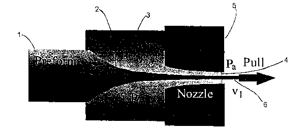
Figure 1 is a schematic cross-sectional view of the embodiment of the present
invention wherein the source material is a glass preform which is heated in an
oven and
extruded through a nozzle.
Figure 2 is a cross-sectional view of a particular configuration of a nozzle
component used in the production of streams and fibers from high viscosity
fluids in
accordance with the present invention.
Figure 3 includes graphs 3A, 3B and 3C wherein graph 3A shows that for a
given ~, different nozzle configurations are constructed in order to provide a
stable stream
and fiber when extruding a high viscosity fluid wherein Figure 3B shows a
nozzle
configuration where ~, = 2 and Figure 3C shows the nozzle configuration when
~, = 6.
Figure 4 is a graph which shows the pressure needed in order to obtain a
stable jet with different nozzle configurations based on different ~, values.
6
CA 02402638 2002-09-09
WO 01/69289 PCT/USO1/07668
DETAILED DESCRIPTION OF PREFERRED EMBODIIVVIENTS
Before the present fiber extrusion device and method are described, it is to
be
understood that this invention is not limited to the particular components and
steps
described, as such may, of course, vary. It is also to be understood that the
terminology used
herein is for the purpose of describing particular embodiments only, and is
not intended to be
limiting, since the scope of the present invention will be limited only by the
appended
claims.
It must be noted that as used herein and in the appended claims, the singular
forms "a", "and," and "the" include plural referents unless the context
clearly dictates
otherwise. Thus, for example, reference to "a dopant" includes a plurality of
dopants and
reference to "the fluid " includes reference to a mixture of fluids, and
equivalents thereof
known to those skilled in the art, and so forth.
Unless defined otherwise, all technical and scientific terms used herein have
the same meaning as commonly understood by one of ordinary skill in the art to
which this
invention belongs. Although any methods and materials similar or equivalent to
those
described herein can be used in the practice or testing of the present
invention, the preferred
methods and materials are now described. All publications mentioned herein are
incorporated herein by reference to disclose and describe the methods and/or
materials in
connection with which the publications are cited.
The publications discussed herein are provided solely for their disclosure
prior to the filing date of the present application. Nothing herein is to be
construed as an
admission that the present invention is not entitled to antedate such
publication by virtue of
prior invention. Further, the dates of publication provided may be different
from the actual
publication dates which may need to be independently confirmed.
DEFINITIONS
The term "ductile" as used herein with reference to certain materials refers
to
materials in a phase that allows the materials to be drawn out into a strand.
Ductile materials
as used herein more preferably refers to materials for the creation of an
optical fiber or
preform that are solid at room temperature (e.g. silicate glass) but are more
easily shaped or
drawn into an elongated fiber at elevated temperatures. The term as used
herein includes
materials in a flowable, or ductile, or heated (or otherwise treated) form.
7
CA 02402638 2002-09-09
WO 01/69289 PCT/USO1/07668
The terms "drawing" and "drawn" as used herein refer to the process of
elongating a stream of material to create an elongated fiber. The drawing
using flow physics
results in a fiber that is consistently sized (in size and shape of cross-
section along its length)
and has significantly reduced lateral dimensions (cross-section) as compared
to the original
liquid stream or preform from which it is drawn. In a drawing process the
material in the
center of a solid cylinder is drawn away from the cylinder and thereby takes
on a narrower
diameter as compared to the cylinder. The length is increased and the diameter
decreased.
The term "focusing fluid" is the fluid used to focus the liquid stream or the
preform. This fluid is preferably a heated gas, although the fluid may also be
a liquid (with
the same or preferably low density as compared to the liquid stream being
focused) that is
immiscible with the liquid stream or the ductile preform.
The term "preform" as used herein refers to a structure that is a precursor to
an optical fiber e.g. a solid cylinder of silica glass. A preform has the
basic structural
elements of an optical fiber (but has a larger diameter), and is generally
heated and drawn
into the narrower elongated configuration of an optical fiber. Preforms can be
made of
numerous different materials, as is known in the art, including glass (e.g.
silicate), plastic,
graphite and the like. In a preferred embodiment, the preform may be comprised
of one or
more photonic bandgap structures (e.g. a group of hollow cylinders) that allow
light to travel
through a hollow portion of the fiber that is surrounded by the photonic
bandgap structure.
The term "high viscosity fluid" and "high viscosity liquid" means a flowable
material which has a viscosity substantially greater than water i.e. 5 times
or more the
viscosity of water. Specifically, the term "high viscosity liquid" is intended
to encompass
fluids wherein the Reynolds number is relatively small, specifically about 1
or less and more
preferably 0.1 or less. Preferred high viscosity fluids include molten silica
glass and molten
glass in various doped forms which are used to produce fiber in order to
transmit information
optically.
DEVICE IN GENERAL
Referring to Figure 1 there is shown a schematic cross-sectional view of the
invention. In this particular configuration the source 1 of the high viscosity
fluid is a glass
preform. At least the end portion 2 of the preform 1 is included within an
oven 3 or the end
to the preform is heated. Further, a focusing fluid such as air or more
preferably a heated
8
CA 02402638 2002-09-09
WO 01/69289 PCT/USO1/07668
inert gas is provided into the oven in order to provide a pressure Po. The
only exit for the
focusing fluid in the pressurized oven is out of an opening 4 created via a
nozzle 5. As the
gas in the oven rushes out of the opening 4 through the nozzle 5 the high
viscosity fluid is
pulled through the nozzle 5 eventually exiting the opening 4 and creating an
elongated fiber
6. This particular embodiment is a schematic embodiment and is merely provided
as
exemplary in order to convey the essence of the invention which is the
formation of a stable
fiber using a focusing fluid to draw out a high viscosity liquid. Those
skilled in the art
reading this disclosure will understand that variabilities will include
factors such as the
temperature and pressure of the oven 3, the shape of the nozzle S, the length
of the nozzle
and the viscosity of the high viscosity fluid being extruded through the
nozzle.
In an alternative embodiment the preform is replaced with a hollow tube
which is preferably a metal tube which is continuously supplied with high
viscosity fluid
such as molten silica glass. Both of these embodiments, i.e. the preform
embodiment and
the molten liquid supplied from a tube opening have variations which make it
possible to
produce hollow fibers. Specifically, the preform can be a preform which is
solid as is shown
in Figure 1 but also may be a preform comprised of a hollow tube which is
elongated and
extruded using the same methodology with the ultimate fiber extruded out of
the opening 4
being a hollow fiber. When the molten silica is supplied by a cylindrical tube
that tube has a
second tube concentrically positioned within it which supplies a gas which is
preferably a
heated inert gas. A heated inert gas must be supplied at a sufficiently high
pressure so that
the hollow fiber is not collapsed in the oven 3. Thus, the pressure within the
hollow tube is
balanced so that it is substantially equal to the pressure inside the oven 3
so that the hollow
tube is not collapsed but rather is extruded out of the opening 4 to form a
hollow fiber. In all
of the embodiments is it preferable that the pressure Po inside of the oven be
sufficiently
high and the configuration of the nozzle be such that the extrusion of gas out
of the opening
4 is supersonic i.e. faster than the speed of sound.
Referring now to Figure 2 there is shown a schematic cross-sectional view of
a nozzle of the invention. The particular configuration of the nozzle is
important in order to
obtain desired results which particularly include the extrusion of the fiber
in a stable manner
out of the opening 4 so that the fiber does not flap or move excessively
resulting in breakage
or non-uniformity of the fiber material being extruded. The geometry of the
internal surface
7 of the nozzle 5 can be determined by the following formula:
9
CA 02402638 2002-09-09
WO 01/69289 PCT/USO1/07668
P(x) - Poe_z
Po is the internal pressure inside the oven 3; ~, is a constant wherein ~, is
greater than
0.635 in order to obtain supersonic expansion and x is a function.
As indicated in Figure 2, for the shown configuration ~, is 5.65; Po is
greater
than or equal to 0.325 for all E greater than or equal to 0. Such will result
in absolute
stability for drawing of a high viscosity fluid in accordance with the
following equation:
Po > ,uiV
L
In the above formula pi is the viscosity of the high viscosity liquid; V1 is
the
velocity of the fiber inside of the nozzle which is substantially greater than
the velocity Vo of
the fiber as it extrudes off of the end of the preform or out of the tube; and
L is the length of
the nozzle and therefore the length over which the focusing fluid such as the
gas provides
substantial energy to the fiber pulling, forcing or drawing it forward out of
the opening 4.
Refernng now to Figure 3 which includes graphs 3A, 3B and 3C it can be
seen that different ~, provide different nozzle configurations which can
result in absolute
stability of the fiber drawn out of the opening 4 of the nozzle. Specifically,
within Figure 3A
plots are drawn for ~, = 2, 4, 6 and 10. Within Figure 3B the nozzle
configuration is shown
for ~, = 2 and within Figure 3C a nozzle configuration is shown for ~, = 6.
Referring now to Figure 4 an additional parameter which is the pressure is
taken into consideration. For a given ~, which is plotted on the X axis the
graph in Figure 4
shows the amount of pressure at the entrance to the oven which is needed in
order to obtain a
stable jet.
FORCES EXERTED FOR HIGH VISCOUS FLUIDS
A model for the production of a glass fiber takes into account a number of
different parameters. The parameter window used (i.e. the set of special
values for the
properties such as flow-rate used, feeding needle diameter, orifice diameter,
pressure ratio,
etc.) should be large enough to be compatible with virtually any desired
viscous liquid or
preform (dynamic viscosities in the range from 10-4 to 1 kg ni's 1)
CA 02402638 2002-09-09
WO 01/69289 PCT/USO1/07668
When the preform-fluid interface is created, the preforrn that emerges from
the outlet of the feeding point is concentrically withdrawn into the nozzle.
After the preforrn
emerges from the exit port, it is accelerated by tangential sweeping forces
exerted by the
focusing fluid (e.g. gas stream) flowing on its surface, which gradually
decreases the
preform cross-section dimensions. Stated differently the gas flow acts as a
lens and focuses
the preform as it moves toward and into the exit orifice of the pressure
chamber. This is
schematically shown in Figure 1.
The forces exerted by the fluid flow on the preform surface should be steady
enough to prevent irregular surface oscillations. Therefore, any turbulence in
the gas motion
should be avoided; even if the gas velocity is high, the characteristic size
of the orifice
should ensure that the gas motion is laminar (similar to the boundary layers
formed on the jet
and on the inner surface of the nozzle or hole).
One of the advantages of the invention is that a desired cooling effect can be
obtained on the surface of the fiber 6 as it exits the opening 4 of the nozzle
5. Specifically,
as the gas exits the opening 4 of the nozzle the gas rapidly expands making it
possible to
absorb energy or the heat on the surface of the fiber 6. This makes it
possible to quickly
cool the fiber which fiber may be at a substantially molten state when exiting
the opening 4.
The cooled fiber is then solidified and can be moved into storage. As shown in
Figure 1 the
oven is pressurized with a pressure Po and has a single nozzle with a single
opening 4.
However, the invention contemplates an embodiment where the oven or
pressurized area
includes multiple nozzles 5 with multiple openings 4 each being supplied by a
different high
viscosity supply source which are each positioned upstream of the opening 4 in
each of the
nozzles 5. In such a configuration only a single oven or heating element may
be required.
Further, because the gas or pressure within the oven or pressure chamber is
sufficient to
focus and move the fiber through the nozzle precise positioning of the nozzle
is not crucial
provided the nozzle and its opening to the outer atmosphere is positioned
substantially
downstream of the flow of the high viscosity fluid.
Using the embodiment as shown in Figure 1 it is possible to provide a coated
fiber by including a coating a material inside the oven 3. Any desired coating
or cladding
material could be included within the gas or other focusing fluid material
provided to the
high viscosity fluid. Still further, in the embodiment where the high
viscosity fluid is
provided to the oven by a tube and that tube encompasses a concentrically
positioned tube
11
CA 02402638 2002-09-09
WO 01/69289 PCT/USO1/07668
which extrudes a gas that gas can include a coating or cladding material which
can be used
to coat or clad the inside of the fiber being created. Those skilled in the
art will contemplate
a range of different materials which are desirably coated onto the inside
and/or outside of the
fiber in order to provide desired optical characteristics or other
characteristics to the fiber
being produced.
OPTICAL FIBER PREFORMS
Optical fibers are typically manufactured by constructing an optical fiber
preform of appropriate composition and drawing a fiber from the preform. The
preform is
constructed and then subjected to a high temperature drawing procedure where
the center of
the solid preform is pulled away thereby increasing the length of the fiber
while
simultaneously decreasing the lateral dimensions of the fiber. A typical
preforrn is a
concentric glass rod having a length of about one meter and an outer diameter
of 20-200
mm. The inner core of the rod is a high purity, low loss glass having a
diameter of about 1-5
mm, and the glass is optionally doped for increased optical performance. The
concentric
outer cylinder, referred to as cladding, is a layer of glass with a lower
index of refraction
than the inner core.
In one particular embodiment, the present invention can be used to construct
elements (tubes and rods) for the construction of optical fibers and/or
optical fiber preforms.
The present invention can be used to form single rods having an inner core and
an outer
cladding core. The core, for example may comprises silica doped with oxides of
germanium
or phosphorous or, alternatively, the fibers may comprise a polymer-clad
silica glass core.
The cladding can be a pure or doped silicate such as fluorosilicate, an
organosiloxane such as
polydimethylsiloxane or a fluorinated acrylic polymer. See e.g., U.S. Pat. No.
6,014,488.
The fibers may also contain a third, outer coating, e.g. a coating with a
resin containing a
pigment to allow color coating of a fiber.
The two layers (or more) layers of the rod are extruded as cylindrical tubes
through concentric needles, and are preferably focused by a heated gas, e.g.
heated air or
heated inert gas. The rods are extruded into an environment that allows the
solidification of
the rods prior to destabilization of the stable microjet. The fibers that are
produced can be
used directly or drawn into a longer, thinner fiber depending on the desired
length and
bandwidth of the optical fiber. Thus, the focusing technology can produced a
long, thin
12
CA 02402638 2002-09-09
WO 01/69289 PCT/USO1/07668
optical fiber for direct use in a cable or, preferably, the produced fiber can
be further drawn
before use in an optical cable.
In a particularly preferred embodiment, the methods of the present invention
are used to construct preforrns for optical fibers based on photonic bandgap
structures. A
S photonic crystal is a structure that repeats a structural element in one or
more dimensions in
space. As a result of multiple reflections, certain wavelengths cannot
propagate in these
structures, and the structure is said to possess a 'photonic band gap' if it
reflects a wavelength
incident from any angle in space. Joannopoulos, J.D. et. al., Photonic
crystals: molding the
flow of light, Princeton University Press, (1995); Cassagne D. et. al. Phys.
Rev. B 52:
82216-82220 (1995).
Initially, it was thought that a large contrast in refractive index would be
needed to achieve a photonic band gap. An example of such a contrast would be
the
refractive index between air and semiconductor, i. e. a refractive index, n,
greater than 3.
Studies have now shown that it is possible to create a two-dimensional
photonic band gap
using a modest contrast in that refractive index between air and silica
(n=1.5), providing the
light has a component traveling parallel to the direction of the rods. Binks
et. al., Electron.
Lett. 31, 1941-1943 (1995). Wavelengths that are normally absorbed by silica
can be
transmitted for much longer distances through air, and because air is not
susceptible to the
nonlinear effects that occur in silica at moderate optical powers; much higher
powers can be
delivered using a photonic bandgap structure. Photonic band gap structures
thus offer the
ability to design new optical properties into conventional materials by
wavelength scale
periodic micro-structuring of the material morphology.
Optical fiber preforms of this type are generally constructed using multiple
rods and/or tubes which are stacked to produce a desired structure. See e.g.,
Cregan et al.,
Science 285:1537-1539 (1999) and Knight et al., Science 285:1476-1478. Such
tubes can be
formed from any material that allows the creation of the photonic bandgap
structure,
including but not limited to silica, glass, graphite, plastic and the like.
See Cregan et al.,
supra, and F. Gadot et al., Appl. Phys. Lett. 71:1780 (1997). The structure is
based on a
defect in an otherwise periodic array of air holes placed within a honeycomb
lattice.
For example, a number of solid silica rods of a constant diameter can be
stacked horizontally to create a structure with a polyagonal cross-sectional
structure. To
create a waveguiding core within the structure, a "defect" must be introduced
into the crystal
13
CA 02402638 2002-09-09
WO 01/69289 PCT/USO1/07668
structure, i.e. a localized region with optical properties different from
those of the fully
periodic structure. This core is surrounded by a "cladding", in this case the
fully periodic
region, which confines the light within the core. Preferably, a larger space
is left in the
center of the preform to allow light to be guided down the central core. The
introduction of
extra air holes into the structure also can allow localized guided modes to
appear within a
band gap.
PHOTO1VIC BANDGAP STRUCTURES
There are two principle ways to reflect light at optical frequencies, total
internal reflection (TIR) and reflection from a periodic dielectric structure.
TIR occurs at the
interface between two dielectrics when it is not possible to simultaneously
match both the
frequency and the phase on both sides of the interface. When light is incident
from the high
dielectric material, it is totally reflected back into the material. This only
occurs if the angle
of incidence is greater than the critical angle. Light can also be reflected
at the interface
between a homogeneous dielectric and a periodic dielectric. This occurs when
multiple
scattered waves in the periodic medium destructively interfere, thereby
prohibiting
propagation inside the periodic medium.
The interaction of light with glass now limits the maximum power that one
can transmit with conventional glass optic fibers, which rely on TIR. Since no
solid
material has an index of refraction of less than one, it is not possible to
have hollow cores
with fibers that rely on TIR because the core must have a larger index of
refraction than the
cladding.
A photonic crystal is a structure that repeats a structural element in one or
more dimensions in space. As a result of multiple reflections, certain
wavelengths cannot
propagate in these structures, and the structure is said to possess a'photonic
band gap' (PBG)
if it reflects a wavelength incident from any angle in space. Joannopoulos,
J.D. et. al.,
Photonic crystals: molding the flow of light, Princeton University Press,
(1995); Cassagne D.
et. al. Phys. Rev. B 52: 82216-82220 (1995). Structures having such photonic
crystals, and
thus possessing PBGs, can be used as optical fibers since they have the
ability to direct light
through hollow portions of the structure that are enclosed by material
possessing an
appropriate photonic bandgap.
14
CA 02402638 2002-09-09
WO 01/69289 PCT/USO1/07668
In one embodiment, the methods of the invention can be used to produced
optical fibers composed of PBG structures. As mentioned above, these
structures allow
propagation of light through a hollow core without certain limitations found
in fibers
utilizing TIR, e.g. the requirement for a higher index of refraction of the
cladding. The use of
air as the medium though which light travels also prevents the absorption of
certain
wavelengths that are absorbed by core materials (e.g., glass) of conventional
optical fibers.
It is possible using the methods of the present invention to make PBG
structures which allow
single mode transmission of light along a hollow structure in a fiber.
Initially, it was thought that a large contrast in refractive index would be
needed to achieve a photonic band gap. An example of such a contrast would be
the
refractive index between air and semiconductor, i.e. a refractive index, n,
greater than 3.
Studies have now shown that it is possible to create a two-dimensional
photonic band gap
using a modest contrast in that refractive index between air and silica
(n=1.5), providing the
light has a component traveling parallel to the direction of the rods. Binks
et. al., Electron.
Lett. 31, 1941-1943 (1995). Wavelengths that are normally absorbed by silica
can be
transmitted for much longer distances through air, and because air is not
susceptible to the
nonlinear effects that occur in silica at moderate optical powers, much higher
powers can be
delivered using a photonic bandgap structure. Photonic band gap structures
thus offer the
ability to design new optical properties into conventional materials by
wavelength scale
periodic micro-structuring of the material morphology.
CONSTRUCTION OF THE OPTICAL FIBER PREFORM
A variety of optical fibers are known, and each of these fibers can be
produced from a specific preform. In a preferred embodiment of the present
invention, the
optical fiber preforms are composed of photonic crystals containing periodic
regions that
create PBGs. Optical fiber preforms of this type are generally constructed
using multiple
rods and/or tubes which are stacked to produce a desired structure. See e.g.,
Cregan et al.,
Science 285:1537-1539 (1999) and Knight et al., Science 285:1476-1478 (1998).
Such tubes
can be formed from any material that allows the creation of the photonic
bandgap structure,
including but not limited to silica, glass, graphite, plastic and the like.
See Cregan et al.,
supra, and F. Gadot et al., Appl. Phys. Lett. 71:1780 (1997). The structure is
based on a
defect in an otherwise periodic array of air holes placed within a honeycomb
lattice.
CA 02402638 2002-09-09
WO 01/69289 PCT/USO1/07668
For example, a number of solid silica rods of a constant diameter can be
stacked horizontally to create a structure with a polyagonal cross-sectional
structure. To
create a waveguiding core within the structure, a "defect" (or hollow section)
must be
introduced to achieve optical properties different from those of the fully
periodic structure.
This core is surrounded by a fully periodic region, which acts as a "cladding"
and confines
the light within the core. Preferably, a space is left in the center of the
preform to allow light
to be guided down the central core. Alternatively, multiple hollow spaces may
be left within
the periodic structure to allow light to travel down multiple channels. The
introduction of
extra air holes into the structure also can allow localized guided modes to
appear within a
band gap.
In another example, a exemplary single mode optical fiber consists of a core
of 10 gm diameter in the center, a cladding of 125 gm diameter surrounding the
core, and a
protective jacket formed by resin covering the cladding. The optical fiber
glass preform is
consequently also comprised of an inner core portion and a cladding coating.
This optical
fiber glass preform itself is conventionally formed by converting a soot body
for forming the
optical fiber porous glass preform into transparent glass.
Conventional methods of producing optical fiber porous glass preforms
include the OVD method (outer deposition type CVD method) and the VAD method.
Preforms for use with the present invention can be produced using these or
other methods of
creating preforms that are known to those skilled in the art.
For example, the general method of production of an optical fiber porous
glass preform using the VAD method involves preparing a seed bar (hereinafter
referred to
as a "target bar") and placing the target bar inside a reaction container, a
reaction chamber
with one end suspended from an upper side so that the target bar can be
rotated around its
longitudinal center axis. Oxygen, hydrogen, and other combustion gases and the
SiCl4 glass
particle material (including a dopant such as GeCl4 if desired) are fed to
oxyhydrogen
burners from which oxyhydrogen flames are generated. In the oxyhydrogen flames
formed
by the combustion gases from the burners, the moisture in the oxyhydrogen
flames and the
SiCl4 undergo a hydrolysis reaction as shown by the following reaction formula
and form
Si02, which is the main component of the glass particles:
SiCl4 +2H20 = Si02 +4HC1
16
CA 02402638 2002-09-09
WO 01/69289 PCT/USO1/07668
These glass particles are sprayed to the lower part of the rotating target bar
and deposited thereon to form the optical fiber soot body.
The optical fiber soot body formed by the VAD method is then converted to
transparent glass to form the optical fiber porous glass preform used for
producing an optical
fiber. Note that an optical fiber soot body converted to transparent glass can
fizrther have
glass particles deposited around it, if necessary. In this case, after
depositing the glass
particles, the soot body is again converted to transparent glass to form the
optical fiber glass
preform.
Other methods for creating conventional optical fiber preforms are described
in U.S. Pat. Nos.: 4,224,046; 4,419,116; 4,421,540; 5,320,660; 5,397,372;
5,672,192.
COATING THE OPTICAL FIBERS
Optical fiber cables containing a plurality of optical fibers for the
transmission of optical signals are well known. Such optical fiber cables
typically include a
core which may have a strength member to carry the axial tensile stress and
axial
compressive forces on the cable. Also located within the core are one or more
tubes. Each
tube typically includes a plurality of optical fibers. The optical fibers
within a tube may be
individually stranded or may be provided in an optical fiber ribbon. A sheath
is provided to
enclose the core including the tubes and the strength member. The optical
fibers included
within such a cable typically include a glass core and one or more claddings
and/or coatings.
During a process of manufacturing a glass optical fiber, a glass fiber is
drawn
from a preform and then coated with one or more coating materials, typically
ultra-violet
light curable materials. The coating materials include, for example, polymeric
compositions
and are applied by one or more coating applicators. The fiznction of the fiber
coating is to
protect the surface of the glass optical fiber from mechanical scratches and
abrasions which
the optical fiber may experience during subsequent handling and use. The
coating or
coatings also influence the fiber's optical characteristics in response to
external mechanical
forces and environmental temperature.
Optical fibers are almost universally color-coded in their end use. There are
numerous colors which are acceptable in most markets, with additional
identification being
made possible by "banding" colored fibers with additional colors or
circumferential striping.
One well-known method of coloring an optical fiber is to apply an ink layer to
an optical
17
CA 02402638 2002-09-09
WO 01/69289 PCT/USO1/07668
fiber having single or dual coating layers so that the total composite optical
fiber includes
primary and secondary coating layers with an outermost ink layer. The ink
coloring layer is
thin, typically 3 to S microns in thickness, and typically includes a carrier
resin and a
pigment system. The carrier resin may typically be a soluble thermoplastic
material or a
ultra-violet (LTV) curable resin. In the former, the ink is applied via a dye
or a transfer
method, such as a felt-tip applicator or roller, and the solvent for the
carrier resin is driven
offby heat to leave the pigmented resin on the fiber. In the LTV system, there
is no solvent.
The liquid resin pigment is cured to a solid state by UV energy. Either ink
involves a
separate step from either optical fiber production or the cabling operation.
An alternative method for color-coding the fiber is to have the color mixed
directly into a secondary (outer) coating of a dual coated optical fiber. The
secondary coating
acts as the carrier resin for the coloring agents.
In one embodiment, the optical fibers are coated during the focusing
procedure using the desired liquid coating as the surrounding, focusing fluid.
For example, a
preform can be heated and focused using an outside liquid composed of a liquid
resin
pigment. As the preform is focused, it is also coated by the liquid resin and
pigment, and
upon expulsion of the focused optical cable it would retain an outer coating
of the focusing
material. The focused optical fiber is then expelled into a gaseous
environment and
immediately cured to a solid state using I1V energy.
PREFORM AND FIBER CHARACTERISTICS
The methodology of the present invention can be used to produce both
preforms which can then be used via conventional drawing technology to produce
fibers or,
alternatively, can be used to produce fibers from preforms produced using
conventional
technology or alternatively the present invention can be used to produce
fibers using
preforms produced according to the methodology described herein. Preforms
which have a
constant diameter along their length can be produced using the technology
described herein
particularly wherein the diameter varies along the length of the fiber or
preform from t1% or
less to as much as X30% or less. Further, fibers can be produced wherein the
diameter along
the length of the fiber is substantially constant for example an optical fiber
of silica glass can
be produced having a diameter of about 1 micron wherein the diameter along the
length of
the fiber varies ~ about 10% or less or more preferably ~ about 1% or less.
18
CA 02402638 2002-09-09
WO 01/69289 PCT/USO1/07668
The methodology of the present invention provides fiber forming stability
which may be enhanced by the appropriate external pressure distribution
provided inside of
the oven or pressure chamber. The stress on the fiber may be dramatically
reduced since the
glass-to-solid contact is avoided by the surrounding focusing fluid or gas
shroud. Complex
fiber concentric structures may be formed by the dramatic reduction of the
radial viscous
stresses compared to the classical extrusion or drawing technology. Molten or
semi-
molten/semi-solid fibers extruded from the nozzle of the invention can be
combined together
to provide phonic bandgap structures of any desired configuration. Not only
are the
characteristics of such photonic bandgap structures and fibers produced via
the present
technology desirable but the processing itself results in desirable
characteristics such as
avoiding clogging of the extrusion device due to the surrounding focusing
fluid and avoiding
contamination of the fiber material due to contact with such solid objects.
Still fizrther, the
fiber quality may be enhanced by the rapid fiber quenching which occurs due to
the
expansion of the gas exiting the nozzle.
EXAMPLES
The following examples are put forth so as to provide those of ordinary skill
in the art with a complete disclosure and description of how to make and use
the present
invention, and are not intended to limit the scope of what the inventors
regard as their
invention nor are they intended to represent that the experiments below are
all or the only
experiments performed. Efforts have been made to ensure accuracy with respect
to numbers
used (e.g. amounts, temperature, etc.) but some experimental errors and
deviations should be
accounted for. Unless indicated otherwise, parts are parts by weight,
molecular weight is
weight average molecular weight, temperature is in degrees Centigrade, and
pressure is at or
near atmospheric. Units of pressure described herein are assumed to be Pascals
units and
viscosity is in kilograms per meter per second, length as in meters and
velocity is in meters
per second.
EXAMPLE 1
FOCUSING OF A CONVENTIONAL OPTICAL FIBER PREFORM
Optical fibers are typically manufactured by constructing an optical fiber
preform of appropriate composition and drawing fiber from the preform. A
preform is a
19
CA 02402638 2002-09-09
WO 01/69289 PCT/USO1/07668
concentric glass rod having a length of about one meter and an outer diameter
of 20 mm. The
inner core of the rod is a high purity, low loss glass such as germanium
silicate glass having
a diameter of about 3 mm. The concentric outer cylinder, referred to as
cladding, is a layer of
glass with a lower index of refraction than the inner core.
Drawing of this preform is performed using a device as illustrated in Figure
1.
Briefly, the end of the preform serves as a delivery source which is heated to
a temperature
that allows the preform material to become ductile. In general, high viscosity
liquid fibers
like the silica require working in the temperature range 700-1000°C
(about 1000 to' 1300°K),
with viscosities ranging from 1,000,000 to 1,000,000,000 cpoises. The preform
is kept in
the heated environment for a sufficient time to become ductile, and then is
introduced from
the preform delivery source into the pressure chamber or oven with the
surrounding focusing
gas. The preform is introduced into the pressure chamber by opening the
preform delivery
source using the force of gravity and optionally a pulse of heated gas into
the delivery source
chamber. The focusing gas is introduced into the pressure chamber via a second
entry port.
The focusing gas may also be heated to maintain the ductility of the preform.
The focusing fluid or gas within the oven 3 rushes towards the exit 4 of the
nozzle S~creating a pull on the highly viscous glass of the preform and tube.
Thus, the
cylindrical structure of the preform is increased in length and decreased in a
cross-sectional
dimension as it moves toward the nozzle 5. Within the nozzle 5 additional
forces are
continually applied along the length "L" of the nozzle until it exits the
opening 4 of the
nozzle 5 and is cooled by the rapid expansion of the gas also exiting the
opening 4 into the
atmospheric pressure Pa. When the fiber 7 exits the opening 4 of the nozzle 5
it is moving at
a velocity "V1" which is substantially faster than the velocity "VD" which it
is moving at
when it is at the end 2 of the preform 1. Further, the gas is expanding
supersonically for ~, >
0.635.
In accordance with the invention it is possible to repeatedly apply the
methodology as shown within Figure 1. Specifically, the fiber 6 exiting the
opening 4 could
be the beginning of the same processing steps whereby that length of viscous
material enters
and oven 3' and enters a nozzle 5' in order to be further stretched, i.e.
increased in its
longitudinal dimension and decreased in its cross-sectional dimension so as to
produce a
fiber of any desired length or dimension.
CA 02402638 2002-09-09
WO 01/69289 PCT/USO1/07668
Because of the different physical phenomenon and the scaling laws for high
viscosity liquids, the nozzle is preferably designed to undergo the extremely
high pressures
needed to draw the fiber 6 by the gas jet through the 200 microns nozzle. For
example,
certain fluids may exhibit a violent flapping or 'whipping' instability upon
exiting the
chamber. This can be accounted for in the design of the device and in the
manner in which
the flow is expelled. For example, the flow and the fiber can discharge into a
vacuum
chamber so that the fiber 6 will flash-cool and will undergo a favorable
pressure gradient
along the vacuum chamber.
EXAMPLE 2
FOCUSING OF A PHOTOIVIC BANDGAP OPTICAL FIBER PREFORM
An optical fiber composed of one or more photonic bandgap structures can be
drawn using the method and devices of the present invention.
Optical fibers based on photonic bandgap structures have been recently
described in the art. These structures have a photonic bandgap structure as
the cladding,
which forces light to remain in the hollow core. The structure is constructed
from silica
tubes and rods, as the contrast between silica and air (1.46 to 1) has been
shown to be
sufficient to produce a bandgap useful for these purposes. Cregan et al.,
supra and Knight et
al., supra. The bandgap created depends upon the geometrical arrangement of
the preform,
and altering structural aspects such as the holes, the size of the holes and
the distances
between the holes will also alter the bandgap created. The PBG structure for
use as an
optical fiber is preferably a structure with a larger volume of air in the
center, e.g. from about
25-45%, and preferably around 30%.
All fibers can be produced using two basic different methods. In accordance
with the preform 1 (as shown within Figure 1) may be a hollow cylinder. In
accordance with
an alternative configuration the molten silica glass is provided by a tube
which extrudes
molten silica and which tube is concentrically positioned around a second tube
which
simultaneously extrudes a gas and maintains the gas at a pressure which is
substantially the
same as the pressure "PD" within the oven or pressure chamber 3. It is
possible to align a
plurality of components such as shown in Figure 1 so that they simultaneously
extrude
hollow semi-solid tubes which come into contact with each other while still in
a semi-solid
state. The tubes can then be made to fuse to each other and form a photonic
bandgap
21
CA 02402638 2002-09-09
WO 01/69289 PCT/USO1/07668
structure when the different tubes are correctly positioned in a manner known
to those
skilled in the art.
EXAMPLE 3
FOCUSING OF ELEMENTS OF A PHOTONIC BANDGAP
OPTICAL FIBER PREFORM
In addition to or in combination with the focusing of Example 2, precursor
elements of the optical fiber PBG preform can be focused prior to construction
and/or fusion
of the preform. The PBG preform are constructed using rods and/or tubes that
are bundled
to create certain even spacing of holes within the structure.
Hollow silica or plastic rods are provided, and then modified using the
focusing methods of the present invention. These tubes can be focused to a
very specific and
small diameter using the methods of the present invention, and the focused
tubes can be used
to produce an optical fiber preform composed of such tubes. The liquid flow is
then focused
into a microjet by a gaseous outer fluid, and the tubes are expelled into a
gaseous
environment where they solidify and are collected.
To construct the preform, several hundred of the hollow, focused tubes are
bundled into a hexagonal array. The diameter of the tubes used to construct
the preform
depend upon the desired size of the holes in the bandgap, as will be apparent
to one skilled in
the art upon reading the present disclosure. The diameter of the tubes will
control the spaces
between the tubes and the resulting periodic space in the optical fiber made
from the
preform. Once the tubes have been stacked; an appropriate number of tubes
(e.g., 5-50 tubes)
are removed to provide one or more hollow cores through which light can
travel.
Following construction, the preform can be fused and prepared to be drawn
into a fiver. Alternatively, the unfused preform can be subjected to an
elongation event such
has that described in Example 1, and fuse either during following said event.
MATHEMATICAL FORMULATION
We consider a Newtonian viscous liquid concentrically drawn through a
convergent-divergent micro-nozzle with length L, and surrounded by a high
speed gas
stream as sketched in Fig. 1, assuming an axisymmetric configuration (the
effect of
asymmetries is described below). The object is to obtain a fiber of final
radius a « L at a
22
CA 02402638 2002-09-09
WO 01/69289 PCT/USO1/07668
given velocity Vl. We define non-dimensional variables x, f, v, and p standing
for the axial
coordinate, fiber radius, liquid velocity, and liquid pressure, which are made
dimensionless
with L, a, Vl, and 3poV1/L, where uo is a reference liquid viscosity.
Furthermore, owing to
the disparity in the residence times of particles of the liquid and the gas,
the gas can be
considered steady for any non-steady liquid motion of interest (including
motions with
wavelengths of the order of the fiber diameter). The gas pressure and
temperature can be
considered as steady variables in the problem, which are functions of the
axial coordinate
only.
For the sake of generality, we can assume a non-linear dependence of the
liquid viscosity with temperature p = p(T~), where T~ is the liquid
temperature. Using
viscous liquids at temperatures around a "drawing" point given by To for which
the liquid
viscosity is ~.b (~ = 105 Pa ~ s in many practical situations), the
relationship between
viscosity and temperature is well fitted by the law
p _ ~.b10-"~Tl~o 1~, where x is a non-dimensional constant (in the case of
common
glasses used in fiber optics, we have To ~ 1000K and x about 10 to 15). One
can then
define a non-dimensional viscosity ~ = 1>/p-0. Thus, neglecting gravity
forces, liquid
acceleration and surface tension forces compared to the much larger viscous
and
pressure forces, one can write the well known mass and momentum conservation
equations for the liquid as:
ate + aX(~v) = 0; aXp = aX(~aXv) /~ + fs ( 1 )
with boundary conditions (i) p = po = (LPo)/(3pV1), f = E1~2 , and v = E-' at
x = 0, and
(ii) v = 1 at x = 1, where E = Vo/Vl, Vo is the intake liquid velocity (or the
glass
preform velocity in glass fiber drawing). fs = F~/(3p,V1/LZ), where Fs ~ i/a
is the axial
resultant per unit volume owing to the viscous stress on the surface, and i is
the
viscous stress on the liquid surface owing to the gas stream. Assuming a high
viscosity liquid, the fiber radial velocity profile is almost perfectly flat
since the
viscous diffusion time t,, ~ pa2p:' is many orders of magnitude smaller than
the
hydrodynamic time to ~ LVl-1 (i.e., pI,(pVla2)-1 «1).
On the other hand, the gas flow is governed by the well known isentropic
compressible 1-D, N-S equations: the gas pressure and temperature distribution
are given by
23
CA 02402638 2002-09-09
WO 01/69289 PCT/USO1/07668
their stagnant values Po and To, respectively, and the nozzle geometry through
A(x), its local
cross section area. The gas expansion in the nozzle provokes a change in the
gas temperature
along the nozzle which is given by
T/To = 1 - OT/To = ( 1 - OP/Po)~Y-I ~~ y (2)
in the isentropic assumption, where y = CP~g~/C"~g~ is the adiabatic gas
constant, Cp~g~
and C,,~g~ v are the usual gas heat coefficients at constant pressure and
density,
respectively, and DP is the pressure drop at a certain point of the nozzle
from its
entrance. This can be approximated by OT - (~y - 1) y I~PPo lTo.
Assuming a slender fiber, its local temperature profile T1 is given by
vBXT~ = ay(ra~Tl)/r (3)
with boundary conditions Tl(x; f) = Ts (T1(x; 0) ~ oo), and T~(0, r) = Ta,
where TS is
the gas temperature at the fiber surface, r is the radial coordinate (made
dimensionless with a) and a = K/(vlpCPa2). P, K and CP are the liquid density,
thermal conductivity and heat capacity, respectively. We can distinguish two
limiting
problems:
1. a » 1: In this case, we can assume T1 = TS. We call this the "gas limited"
(GL)
case.
2. a « 1: In this case, we can assume T1= To. We call this the "isothermal"
(IT)limit.
In the GL case, the temperature profile of the fiber in the radial direction
can
be considered uniform, and the temperature is controlled by the ability of the
gas to trans-
port the heat through its thermal boundary layer. In the other limit, IT, the
liquid bulk
remains at the initial To temperature because the inability of the liquid
thermal boundary
layer to evacuate the liquid heat.
From the point of view of the fiber shape homogeneity and quality, the GL
case is the most interesting one, because it involves a controlled temperature
(i.e., material
quenching and enhanced amorphous structure) and a substantial increase in the
fiber
viscosity (and therefore an increase in its "mechanical resistance") as it
proceeds towards the
nozzle exit, which immediately suppresses most instabilities by itself without
the need of a
24
CA 02402638 2002-09-09
WO 01/69289 PCT/USO1/07668
further refinement of the process, although it requires a limited production
velocity, given by
Vl « KL/(pCPa2). These velocities can be accomplished by the classical simple
hot
drawing process in some cases, but the temperature control is in this process
severely
limited.
On the contrary, the IT case is challenge because it is most unstable and
difficult to control, but its reward is its large productivity (large E
values). Because of this,
we will focus on this particular limit, also considered by Yarin et al. (1999)
in the case of
simple drawing. We will show that the use of the co-flowing high speed gas
stream provide
the means to (i) completely stabilize the fiber, to (ii) yield fiber
homogeneity and/or shape
control, and to (iii) control fiber quenching. Although we are interested in
the IT case, for the
sake of generality in the following we will consider the temperature
variations in the liquid
for the GL limit also.
Gas boundary layer, viscous shear stress, and heat transfer on the fiber
surface - The gas boundary layer on the liquid jet has a thickness of the
order of 8
O((p,gLPo 1)v2 (RgTo)'ia), where Po, To, and p,g are the stagnation gas
pressure and temperature
at the nozzle entrance, and 'g is the gas viscosity, respectively, and Rg =
Cp~g~ - C"~g~ as usual.
The tangential viscous stress i acting on the jet surface, owing to the much
faster gas stream,
is then of the order of
i ~ O((pgL-1Po)vz (RgTo)'~a. Comparing the axial resultant per unit volume of
the
viscous stress on the surface, FS, of the order of FS ~ i/a, with the
extensional (axial)
resultant of the viscous stress, F,,, of the order of F,, ~ pVl/L2, and since
Po ~ p.Vl/L, one obtains
Fg - F~ ~ (~B/lAl)1/2 ~T~~12)1/4 L/a (4)
We seek for production velocities Vl much larger than p,gli lL2a 2(RgTo)1~2
(of
the order of about 10-3 to 10-2 m/s in practical situations), for which FS «
F,,, and the
contribution of the surface stress is negligible versus the axial component of
the normal
pressure stress, of the order of PoI,-' ~ p.VIL-2. Thus, the momentum equation
in (1) reduces
to 8Xp = aX(~aXV)/~.
Since the gas temperature variations can be approximated by equation (2),
considering a portion of the threadline, its temperature variation owing to
the heat transfer
through the gas thermal boundary layer (of the order of S since the gas
Prandtl number is of
the order 1 ) is of the order of
CA 02402638 2002-09-09
WO 01/69289 PCT/USO1/07668
L ~T
DT ~ PCPaYIx~ 8
where x° the gas thermal conductivity at temperature To. In practical
situations, we
may have L(pCPaVI)-lKoB-1 « 1; however, owing to the strong dependence of
viscosity with temperature, these limited liquid temperature variations (about
5 to
20% of To in practice) are sufficient to increase the liquid viscosity by
orders of
magnitude, which is a mechanism that suppresses most instabilities by itself.
It should be discussed here that owing to the high P° values needed
to drive
the fiber, the gas undergoes its maximum expansion and consequently its
maximum cooling
right after the nozzle exit. In the GL case, the fiber is sufficiently
hardened to remain
unaffected by this expansion. In the IT limit the nozzle exit geometry and the
fiber winding
system after the exit should be carefizlly designed to avoid fiber shape
inhomogeneities.
Nozzle geometry - In order to reduce the problem of the nozzle geometry to a
single parameter, without lost of generality on our aimed task, we have
selected pressure
distributions of the type:
P(x) - poe ~"
where ~, is a free parameter, and the set of parameters {p°, ~,} will
be optimized for
the requirement of an unlimited fiber drawing (i.e. fiber production) with a
minimum
energy consumption (minimum pa). Thus, given stagnation pressure p°, we
seek ~,
values for which the drawing is absolutely stable for any (unlimited) given
"productivity" E value.
Fiber stability. Suppression of the non-symmetric in-stability (frber whipping
- Considering po values of the order unity, for values of ~, < 0.635, one
obtains a sub-sonic
gas flow along the nozzle, except at the nozzle exit. Calculating the pressure
distribution on
the fiber when it undergoes a small departure from the axisymmetric
configuration (we recall
that gas and liquid flows are uncoupled with time, and that the gas flow can
be calculated in
steady regime), one obtains a strong destabilizing effect. On the contrary,
for ~, values
sufficiently larger than 0.635, the resulting supersonic part of the nozzle
flow provokes the
reversal erect: any departure from the basic axisymmetric configuration
provoke a strong re-
26
CA 02402638 2002-09-09
WO 01/69289 PCT/USO1/07668
aligning azimuthal pressure distribution, which suppress any possible
incipient fiber
whipping.
Thus, we will consider ~, > 1 values only in our analysis.
Suppression of the "drawing resonance " axisymmetric instability. IT case -
Consider
the small perturbations problem given by
F = fe( 1 + ae''T), v = ve( 1 + ~e''t)
and governed by equations ( 1 ), where fe(x) and ve(x) are the steady values
of the
problem for the given boundary conditions, a(x) and ~i(x) are complex
fi~nctions with
argument small compared to 1, and A is the complex perturbation growth rate.
Thus,
a and (3 are governed by a set of 2 complex ODES with homogeneous boundary
conditions that can be readily obtained from equations ( 1 ) (problem not
written here
for simplicity; see [1]), which determine the eigenvalue A, and whose real
part Ar
gives the growth factor in time. We give the value Ar as a function of po for
~, = 6
and E = 120.
For every given E and ~, values, there is a corresponding po value above
which any axisymmetric instabilities are suppressed. In Figure 3A we plot the
curves which
divide the {E, po} space into stable (above the curve) and unstable (below the
curve)
parametrical sub-spaces, for several ~, values of practical interest. One may
immediately note
from this plot that for every given ~, value, there is a particular limiting
value of po for
stabilization above which the fiber is stable for any value of E > 1. In
figure 4, we plot these
limiting po values as a fiznction of ~,, and obtain a universal minimum value
of the pressure
above which the fiber is absolutely stable regardless the fiber productivity
E.
A minimum limiting pa value about 0.33 around the point ~,- 5.65 can be
found, corresponding to the optimum nozzle shape with a significant supersonic
region
(from x = 0:112 to x = 1) for a single parameter geometry. In this case, given
a desired fiber
diameter a and fiber production velocity Vl, the minimum gas pressure Po
necessary to have
absolute stability is given by the simple expression:
Po = p,V1/a (8)
with a nozzle shape as shown in Figure 2.
27
CA 02402638 2002-09-09
WO 01/69289 PCT/USO1/07668
A practical case - Consider the production of 173 Km/day of a fiber with a
diameter of 200 p,m of an alumino-silicate glass (~ = 103 Pa ~ s at To = 1
SOOK). The
minimum pressure required is then Po = 2 x 10 Mpa, with a nozzle exit pressure
of PS = Po x
a s.6s = 70.3 Kpa. Assuming that the nozzle exits into an adapted pressure
chamber, at a
temperature Ts = 300 K, the isentropic compression of the gas from the exit
chamber
(recirculation) rises the temperature to the required To - 1 SOOK. The liquid
has density,
thermal conductivity and heat capacity p = 3000 Kg ~ m 3, K = 1 J(m ~ s ~
K)'1, and CP =
1000 m2 (s2 ~ K), respectively. The nozzle design should minimize the neck-
fiber gap with-
out compromising stability. A feasible solution is a nozzle with a length of
lOmm, a neck
diameter of l.3mm at 1. l2mm from the entrance, and exit diameter of 1.28mm.
Considering
the presence of the fiber, this nozzle has a minimum (sonic) cross section
area of 0.32 mm2 .
Since Vl = 2 m ~ s' » KL/(pCPa2) = 0.3 m ~ s 1, the fiber can be considered
quasi-
isothermal (IT limit). The minimum theoretical power consumption of the plant
is then W =
9.54 KW, with a gas flow rate of about 1 Us at PS = 0.7 Bar. Scale-up is
straightforward.
A fizrther refinement of the nozzle geometry is possible introducing new
geometrical parameters (the minimum pa value may be further optimized). This
refinement
does not limit the generality of the above analysis.
3201 (1999).
[1] A. L. Yarin, P. Gospodinov, O. Gottlieb, M. D. Graham, Phys. Fluids 11,
While the present invention has been described with reference to the specific
embodiments thereof, it should be understood by those skilled in the art that
various changes
may be made and equivalents may be substituted without departing from the true
spirit and
scope of the invention. In addition, many modifications may be made to adapt a
particular
situation, material, composition of matter, process, process step or steps, to
the objective,
spirit and scope of the present invention. All such modifications are intended
to be within
the scope of the claims appended hereto.
28