Note : Les descriptions sont présentées dans la langue officielle dans laquelle elles ont été soumises.
CA 02403089 2005-O1-28
APPARATUS FOR SUPPLYING LIf,~UID~CENERATING PLASMA
Technical Field
The present invention relates to an apparatus for supplying liquid for use
in a plasma disinfection system for sterilizing and disinfecting surfaces of
objects
such as medical instruments with gaseous plasma, and, more particularly, to an
apparatus for supplying liquid which is capable of automatically supplying
liquid
for generating plasma, i.e., hydrogen peroxide, in increments of a fixed small
amount.
Backg~und Art
to Various methods of sterilization and disinfection have been used for the
sterilization of different types of disposable and reusable medical equipment.
Among these methods, a method of sterilization and disinfection by steam or by
dry heat has been used extensively used. However, this method of sterilization
and disinfection cannot be applied to sterilize materials that are adversely
affected
by such heat or steam.
Ethylene oxide (Et0) gas has also been used but suffers from the
drawback that it may leave toxic residues on the articles to be sterilized,
which
may have adverse effects on patients who come into contact with such articles.
Consequently, with this method, an additional procedure required to remove
2 o residual ethylene oxide from some sterilized items also causes the
ethylene oxide
sterilization procedure to be high in cost and to take a long time.
Among methods for overcoming the aforesaid drawbacks, there is a
method using hydrogen peroxide as a precursor of active species in a low
temperature plasma system. This method is generally carried out in such a way
that an object to be sterilized and disinfected is first brought in to contact
with
gaseous hydrogen peroxide as a pre-treatment, and the object is finally
sterilized
and disinfected by hydrogen peroxide plasma generated by supply of a required
1
CA 02403089 2005-O1-28
amount of electric power, so as to reduce a length of time required to
sterilize and
disinfect by plasma.
In the above low temperature plasma disinfection system, an apparatus for
supplying hydrogen peroxide employs a capsule type cassette system containing
a
certain amount of hydrogen peroxide solution. The hydrogen peroxide solution
contained in the capsule is fed to a solution-feeding pipe by means of an
injection
pump, and the fed hydrogen peroxide solution in a liquid phase is vaporized by
a
vaporizer, which is then fed into a sterilization reactor.
With the above capsule type cassette system, however, a used cassette
must be replaced by a new one with ten capsules in it after the sterilization
process
is carried out ten times since one capsule is used in one sterilization
process. In
addition, the above vaporizer has drawbacks that the above apparatus for
supplying
an extremely small fixed amount of liquid is very complicated and very
expensive.
Disclosure of the Invention
Accordingly, the present invention has been made keeping in mind the
above problems occurring in the prior art, and an object of the present
invention is
to provide an apparatus for supplying liquid for generating plasma, which is
intended to avoid inconvenience caused by frequent replacement of cassettes in
the
capsule type cassette system and to reduce its manufacturing cost by
simplification
2 0 of its configuration, and which is also intended to automatically supply
hydrogen
peroxide liquid for generating plasma in increments of a fixed small amount.
In order to accomplish the above object, the present invention provides an
apparatus for supplying liquid for generating plasma to a reaction chamber to
sterilize and disinfect an item wrapped in a packaging material in the
reaction
2 5 chamber, comprising: an automatic feeder for automatically feeding an
extremely
small fixed amount of liquid for generating plasma via a first discharging
pipe by
controlling a rotational speed of a DC motor, a vaporizer connected to the
first
discharging pipe of the automatic feeder and having a first heater for
vaporizing
the fed liquid; a second heater surrounding a second discharging pipe
connected
2
. . ,.~., ~~,..~..
CA 02403089 2005-O1-28
between the vaporizer and the reaction chamber to prevent any condensation of
the
vaporized liquid in the second discharging pipe; and a temperature controller
electrically connected to the first and second heaters to control temperatures
thereof.
The automatic feeder may comprise: a DC motor having a retarder; a
proportional control circuit connected to the DC motor by a feed-back signal
for
controlling the speed of operation of the DC motor; a feeding screw connected
to a
rotating shaft of the DC motor; a supporting member engaged with the feeding
screw to be moved back and forth along the feeding screw by rotation of the
1 o feeding screw; an injection piston coupled to the supporting member to be
linearly
moved together with the supporting member; an injection cylinder supported by
two fixing plates and receiving the injection piston, the injection cylinder
being
provided with a feeding valve adapted to be opened at the time of retraction
of the
injection piston and an exhaust valve adapted to be opened at the time of
extension
of the injection piston; a liquid supplying container connected to the feeding
valve
of the injection cylinder for supplying liquid for generating plasma to the
injection
cylinder; and a displacement sensor provided at the fixing plate to detect a
position
of the injection piston.
Brief Description of the Drawings_
2 o The above and other objects, features and advantages of the present
invention will be more clearly understood from the following detailed
description
taken in conjunction with the accompanying drawings, in which:
FIG. 1 is a schematic view of a plasma sterilization system to which an
apparatus for supplying liquid according to the present invention is applied;
2 5 FIG. 2 is a schematic view of the apparatus for supplying liquid, which is
an essential part of the present invention; and
FIG. 3 is a schematic view of an automatic feeder of FIG. 2.
3
CA 02403089 2005-O1-28
Best Mode for Carrying Out the Invention
Reference now should be made to the drawings, in which the same
reference numerals are used throughout the different drawings to designate the
same or similar components.
FIG. 1 is a schematic view of a plasma sterilization system to which an
apparatus for supplying liquid according to the present invention is applied,
which
is a system for sterilizing and disinfecting an item in a gaseous plasma.
The plasma sterilization system uses a hydrogen peroxide solution 12 as a
l0 source for generation of the plasma to sterilize and disinfect surfaces of
an item 9
to be sterilized such as medical instruments, and also uses hydrogen peroxide
as an
active species during generation of the plasma. Prior to the generation of the
plasma (which is generated by electric discharge of gas), a pre-treatment is
carried
out with gaseous plasma.
A reaction chamber 1 receives an item 9 to be sterilized such as medical
or surgical instruments, which is wrapped in a packaging material 10. The
reaction chamber 1 is provided at its inner and upper position with an anode 2
and
at its inner and lower position with a cathode- 3. The anode 2 is connected to
a
mass flow controller 4, which is in turn connected to an injection heater 5.
The
2 0 cathode 3 is connected to an impedance matching circuit 6, which is in
turn
connected to a plasma power source 8 through an impedance matching controller
7. Furthermore, disposed below the reaction chamber 1 is a vacuum pump 11,
which serves to draw out air of the reaction chamber 1.
In the plasma sterilization system according to the present invention, after
2 5 the item 9 to be sterilized, such as medical or surgical instruments,
which is
wrapped in the packaging material 10, is placed in the reaction chamber 1, the
reaction chamber 1 is closed, and air is drawn out of the reaction chamber 1
by
means of the vacuum pump 11 to form a vacuum inside of the reaction chamber 1.
At this point, the hydrogen peroxide solution 12 in a liquid phase is turned
into
3 0 gaseous hydrogen peroxide by means of the injection heater 5, and the
gaseous
hydrogen peroxide is adjusted to a predetermined pressure (approximately 0.1-
10
4
CA 02403089 2005-O1-28
Ton) by means of the mass flow controller 4 and then injected into the anode
2.
The hydrogen peroxide remains in the chamber for a predetermined time period
(approximately 30 minutes) to allow extensive contact between the hydrogen
peroxide and the item 9 to be sterilized.
After the electric power is set to a desired level using the plasma power
source 8, the power is adjusted by the impedance matching controller 7 so that
a
level corresponds to a resistance value of the gaseous hydrogen peroxide in
the
reaction chamber 1, and then reaches the cathode 3 through the impedance
matching circuit 6, thereby supplying the optimal power to the cathode 3. By
the
1 o supply of the power to the cathode 3, plasma is generated between the
cathode 3
and the anode 2.
The plasma remains in the reaction chamber 1 for a sufricient time
(approximately 50 minutes) to allow complete sterilization, although the
sterilization can be effected in periods as short as 5 minutes from initial
plasma
generation, depending on the plasma power source 8 that is applied to the
cathode
3 and a concentration of the hydrogen peroxide.
Therefore, it is preferable to apply the optimal power in order to obtain
the optimal efficiency of sterilization since the efficiency of sterilization
relies on
the plasma power source 8 as well as the concentration of hydrogen peroxide.
2 0 Since the packaging material 10 is used to wrap the item 9 to be
sterilized,
and is then placed in the reaction chamber 1, the preferred material of the
packaging material is a fibriform polyethylene or polyethylene terephthalate
to
have favorable gas permeability. Alternatively, although the packaging
material
10 may be a paper to reduce manufacturing costs, longer processing times may
be
2 5 required to achieve complete sterilization because of possible
interactions of
hydrogen peroxide and other reactive species with the paper.
In the plasma sterilization system according to the present invention, a
pressure of gaseous hydrogen peroxide as reaction gas is set to less than 10
Torr,
and a high-frequency (RF 13.56MHz) capacity combination type, in which the
3 0 high-frequency power is intermittently applied in the form of pulse, is
used to
generate plasma with a temperature of less than 100.
5
CA 02403089 2005-O1-28
In the present invention, the reason why the intermittent application of
high-frequency power is employed is that the intermittent application prevents
overheating of the reaction gas in the reaction chamber 1 as well as
overheating of
the item 9 to be sterilized. The intermittent application of power is carried
out in
such a way that high-frequency power is applied for 0.5 ms and then turned off
for
1 ms prior to re-application.
As described above, hydrogen peroxide is injected into the anode 2 of the
reaction chamber 1 in order to carry out the pre-treatment. At this point,
preferably a concentration of the gaseous hydrogen peroxide is 0.05 to 10
mglliter,
l0 but a higher concentration of hydrogen peroxide will result in shorter
sterilization
times since efficiency of the sterilization becomes higher.
The minimum concentration of hydrogen peroxide injected into the
reaction chamber 1 is approximately 0.125 mg/liter. When the hydrogen
peroxide is injected at an appropriate concentration, auxiliary gases such as
oxygen, nitrogen, argon or the like may be added into the reaction chamber.
When an item 9 to be sterilized such as medical or surgical instruments is
sterilized by the present invention, no additional steps are required to
remove
residual hydrogen peroxide from the sterilized item 9 or its packaging
material 10,
since the hydrogen peroxide is decomposed into non-toxic products during the
2 0 plasma treatment, unlike a conventional ethylene oxide process, which is a
conventional gas sterilization process.
FIG. 2 is a schematic view of the apparatus for supplying liquid, which is
an essential part of the present invention.
The apparatus for supplying liquid is designed to cause liquid for
2 5 generating plasma supplied from an automatic feeder 20 to be vaporized at
a
vaporizer 24 disposed between a fist discharging pipe 40 and a second
discharging
pipe 23 and then to be supplied to an reaction chamber 1. The automatic feeder
is adapted to automatically supply an extremely small fixed amount of liquid
for generating plasma to the first discharging pipe 40 by a DC motor 31. The
3 0 first discharging pipe 40 is connected at its end to the vaporizer 24,
which
vaporizes the liquid supplied through the first discharging pipe 40 by a first
heater
6
CA 02403089 2005-O1-28
26. The second discharging pipe 23 connected to the vaporizer 24 is provided
at
its outer surface with a second heater 22 to prevent condensation of the
vaporized
liquid supplied to the reaction chamber 1. Temperatures of the first and
second
heaters 26 and 22 are controlled by a temperature controller 25, which is
electrically connected thereto.
As shown in FIG. 3, the automatic feeder 20 causes an injection piston 45
connected to the DC motor 31, whose speed is controlled by a feed-back signal
from the proportional control circuit 12 of the controller, in order to be
linearly
moved at a desired speed. Consequently, it is possible to control amount of
liquid
1o supplied per unit time, which is determined from a cross section of the
injection
piston 45 and a displacement volume per unit time by driving of the injection
piston. After the liquid whose volume corresponds to that of an injection
cylinder
46 is depleted, the DC motor 31 is reversely rotated to cause the injection
piston 45
to be retracted, thereby allowing the liquid in a liquid supplying container
48 to be
automatically injected into the injection cylinder 46.
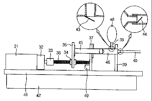
The automatic feeder 20 will now be described in more detail. The DC
motor 31, which includes a retarder 32, is controlled by the proportional
control
circuit 42, by a feed-back signal. A rotating shaft of the DC motor 31 is
connected to a feeding screw 36 by a coupling 33, such that the feeding screw
36 is
2 0 rotated in a state of being aligned with the rotating shaft. An end of the
feeding
screw 36 is supported by a fixing plate 37.
The feeding screw 36 is provided thereon with a supporting member 35
via a feeding nut 34 so that the supporting member 35 is moved back and forth
along the feeding screw 36 by rotation of the feeding screw 36. The supporting
member 35 is connected to the injection piston 45, which is linearly moved
along
an axis parallel to the feeding screw 36. The injection piston 45 is air-
tightly
received in an injection cylinder 46, which accommodates the linear movement
of
the injection piston 45, and is supported by two fixing plates 37 and 39. The
injection cylinder 46 is provided with a feeding valve 43 adapted to be opened
at
3 0 the time of retraction of the injection piston 45 and an exhaust valve 44
adapted to
be opened at the time of extension of the injection piston 45, so as not to
hinder the
7
CA 02403089 2005-O1-28
linear movement of the injection piston 45.
The injection cylinder 46 is communicated with the liquid supplying
container 48 for storing liquid for generating plasma, which is provided with
the
feeding valve 43 at its lower end. The fixing plate 37 is provided with a
displacement sensor 49 for detecting a position of the injection piston 45.
The
DC motor 31 and the fixing plates 37 and 39 are fixedly mounted on a mounting
member 41.
A process for automatically supplying an extremely small fixed amount of
hydrogen peroxide solution to the reaction chamber 1 using the apparatus for
supplying liquid according to the present invention will now be described.
After liquid for generating plasma is first filled in the injection cylinder
46, the DC motor 31 is activated by the proportional control circuit 42.
Consequently, the feeding screw 36 connected to the rotating shaft of the DC
motor 31 is rotated, thereby causing the supporting member 35 engaged
therewith
to be linearly advanced along the feeding screw 36.
When the supporting member 35 is moved forwardly, the injection piston
45 coupled to the supporting member 35 is also moved forwardly, so that an
amount of liquid in the injection cylinder 46 corresponding to a distance by
which
the injection cylinder is moved, is discharged.
2 0 Thereafter, the DC motor 31 is controlled by the proportional control
circuit 42 to advance the injection piston 45 at a desired velocity. By this
advance of the injection piston 45, the liquid in the injection cylinder 46 is
automatically supplied in increments of a fixed small amount. In this case, an
amount of the supplied liquid can be derived from a transfer distance per unit
time
of the injection piston 45 and a cross section of the inside of the injection
cylinder
46. From the transfer distance per unit time of the injection piston 45, a
rotational
velocity of the DC motor 31 can be derived, so that a time period required to
supply a predetermined small amount of liquid can be calculated. Accordingly,
the liquid in the injection cylinder 46 is automatically supplied in
increments of a
fixed small amount. At this point, the feeding valve 43 of the injection
cylinder
46 is closed while the exhaust valve 44 is opened.
s
CA 02403089 2005-O1-28
The liquid discharged from the exhaust valve 44 of the injection cylinder
46 is vaporized by the first heater 26 mounted on the vaporizer 24, and then
injected into the reaction chamber 1 through the second discharging pipe 23,
In
the present invention, since the second discharging pipe 23 connected to the
vaporizer 24 is fully covered with the second heater 22, the liquid flowing in
the
second discharging pipe 23 can be maintained in a vaporized state, and there
is no
temperature difference between the inside of the pipe and the outside of the
pipe.
Temperatures of the first and second heater 26 and 22 are constantly
controlled by
the temperature control circuit 25.
1o By generating plasma from the vaporized liquid supplied to the reaction
chamber 1, the plasma sterilization process is carried out.
As the injection piston 45 continues to advance, the injection piston 45 is
detected by the displacement sensor 49 provided at the fixing plate 37
supporting
the injection cylinder 46. When the injection piston 45 is completely moved
forwardly until depletion of the liquid in the injection cylinder 46, the
injection
piston 45, i.e., the depletion of the liquid is detected by the displacement
sensor 49.
By a signal from the displacement sensor, the DC motor 31 is rotated in a
reverse
direction to cause the injection piston 45 to be retracted, so that the liquid
in the
liquid supplying container 48 is filled in the injection cylinder 46 through a
liquid
supplying pipe 38. At this point, the exhaust valve 44 of the injection
cylinder 46
is closed while the feeding valve 43 is opened.
industrial Applicability
As described above, the present invention provides an apparatus for
supplying liquid for use in a plasma disinfection system used in hospitals,
which is
2 5 capable of supplying an extremely small amount of liquid to a
sterilization and
disinfection chamber or a reaction chamber. The apparatus for supplying liquid
according to the present invention enables its configuration to be simplified
and its
manufacturing cost to be lowered, and can be used for a long time with only
one
filling procedure of liquid without frequent replacement of a cassette
containing
9
CA 02403089 2005-O1-28
liquid.
Although the preferred embodiment of the present invention has been
disclosed for illustrative purposes, those skilled in the art will appreciate
that
various modifications, additions and substitutions are possible, without
departing
from the scope and spirit of the invention as disclosed in the accompanying
claims.
to