Sélection de la langue

Search

Sommaire du brevet 2403319 

Énoncé de désistement de responsabilité concernant l'information provenant de tiers

Une partie des informations de ce site Web a été fournie par des sources externes. Le gouvernement du Canada n'assume aucune responsabilité concernant la précision, l'actualité ou la fiabilité des informations fournies par les sources externes. Les utilisateurs qui désirent employer cette information devraient consulter directement la source des informations. Le contenu fourni par les sources externes n'est pas assujetti aux exigences sur les langues officielles, la protection des renseignements personnels et l'accessibilité.

Disponibilité de l'Abrégé et des Revendications

L'apparition de différences dans le texte et l'image des Revendications et de l'Abrégé dépend du moment auquel le document est publié. Les textes des Revendications et de l'Abrégé sont affichés :

  • lorsque la demande peut être examinée par le public;
  • lorsque le brevet est émis (délivrance).
(12) Demande de brevet: (11) CA 2403319
(54) Titre français: POUTRELLE TRANSVERSALE SERVANT A SUPPORTER LES SIEGES AVANT D'UNE VOITURE
(54) Titre anglais: FRONT ROW CROSS CAR BEAM SEAT BRIDGE
Statut: Réputée abandonnée et au-delà du délai pour le rétablissement - en attente de la réponse à l’avis de communication rejetée
Données bibliographiques
(51) Classification internationale des brevets (CIB):
  • B60N 02/005 (2006.01)
(72) Inventeurs :
  • NEALE, COLIN G. (Etats-Unis d'Amérique)
(73) Titulaires :
  • INTIER AUTOMOTIVE INC.
(71) Demandeurs :
  • INTIER AUTOMOTIVE INC. (Canada)
(74) Agent: JEFFREY T. IMAIIMAI, JEFFREY T.
(74) Co-agent:
(45) Délivré:
(22) Date de dépôt: 2002-09-13
(41) Mise à la disponibilité du public: 2003-03-13
Licence disponible: S.O.
Cédé au domaine public: S.O.
(25) Langue des documents déposés: Anglais

Traité de coopération en matière de brevets (PCT): Non

(30) Données de priorité de la demande:
Numéro de la demande Pays / territoire Date
60/322,129 (Etats-Unis d'Amérique) 2001-09-13

Abrégés

Abrégé anglais


A bridge assembly for supporting a seat in a motor vehicle having opposing B-
pillars and a floor extending therebetween. The bridge assembly includes a
rear cross car
beam having a rear length extending between a rear driver end and a rear
passenger end.
The rear driver and rear passenger ends are fixedly secured to each of the B-
pillars such
that the rear cross car beam extends over the floor spaced apart therefrom. A
front
support structure is spaced forward of the rear cross car beam. In addition,
the bridge
assembly includes a crossing support extending between the rear cross car beam
and the
front support structure for strengthening the bridge assembly.

Revendications

Note : Les revendications sont présentées dans la langue officielle dans laquelle elles ont été soumises.


What is claimed is:
1. A bridge assembly for supporting a seat in a motor vehicle having
opposing B-pillars and a floor extending therebetween, said bridge assembly
comprising:
a rear cross car beam including a rear length extending between a rear driver
end
and a rear passenger end, said rear driver end and said rear passenger end
fixedly secured
to each of the B-pillars such that said rear cross car beam extends over the
floor spaced
apart therefrom;
a front support structure spaced forward of said rear cross car beam; and
a crossing support extending between said rear cross car beam and said front
support structure for strengthening said bridge assembly.
2. A bridge assembly as set forth in claim 1 wherein said crossing support
includes a plurality of cross beams extending between said rear cross beam and
said front
support structure.
3. A bridge assembly as set forth in claim 2 wherein said front support
structure includes support legs extending downwardly therefrom.
4. A bridge assembly as set forth in claim 3 wherein said support legs are
fixedly secured to the floor.
5. A bridge assembly as set forth in claim 4 wherein one of said plurality of
cross beams intersects another of said plurality of cross beams.
6. A bridge assembly as set forth in claim 1 including a panel supported
above the floor.
7. A bridge assembly as set forth in claim 6 wherein said front support
structure includes a support plate fixedly secured to the floor.
6

8. A bridge assembly as set forth in claim 7 wherein said panel is partially
supported above the floor by said support plate.
9. A bridge assembly as set forth in claim 8 wherein said panel defines a
plurality of mounting bores.
10. A bridge assembly as set forth in claim 9 including a plurality of cross
beams extending between said rear cross beam and said support plate.
11. A bridge assembly for supporting a seat in a motor vehicle having
opposing B-pillars and a floor extending therebetween, said bridge assembly
comprising:
a rear cross car beam including a rear length extending between a rear driver
end
and a rear passenger end, said rear driver end and said rear passenger end
fixedly secured
to each of the B-pillars such that said rear cross car beam extends over the
floor spaced
apart therefrom;
a crossing support extending forwardly out from said rear cross car beam; and
a support plate fixedly secured to said plurality of cross beams for
supporting said
plurality of cross beams above the floor.
12. A bridge assembly as set forth in claim 11 wherein said cross support
includes a plurality of cross beams.
13. A bridge assembly as set forth in claim 12 wherein said support plate is
fixedly secured to the floor.
14. A bridge assembly as set forth in claim 13 including a panel supported
above the floor and said plurality of cross beams.
15. A bridge assembly as set forth in claim 14 wherein said panel extends
between said rear driver and rear passenger ends of said rear cross car beam.
7

16. A bridge assembly as set forth in claim 15 wherein said panel defines a
plurality of mounting bores.
17. A bridge assembly as set forth in claim 16 including a plurality of panels
supported above the floor by said plurality of cross beams.
18. A bridge assembly as set forth in claim 17 wherein each of said plurality
of panels is supported above the floor by said rear cross car beam.
19. A bridge assembly as set forth in claim 18 wherein each of said plurality
of panels defines a plurality of mounting bores.
8

Description

Note : Les descriptions sont présentées dans la langue officielle dans laquelle elles ont été soumises.

CA 02403319 2002-09-13
FRONT ROW CROSS CAR BEAM SEAT BRIDGE
Background of the Invention
1. Field of the Invention
The invention relates to a bridge assembly for supporting a seat of a motor
vehicle. More particularly, the invention is directed to a bridge assembly
that supports a
front seat above a floor of a motor vehicle.
2. Description of the Related Art
A motor vehicle typically includes one or more rows of seats located
throughout a
passenger compartment for supporting passengers thereon. A front row, for
example,
may include a pair of bucket-type seats or a single bench-type seat at a front
portion of
the passenger compartment. Typically, each seat is supported above a floor of
the motor
1 S vehicle by front seat risers. But these structures have the undesirable
effect of dividing
the space below the seats) into many smaller areas, making storage of items
thereunder
more difficult.
Various structural members have been developed to support the seats) while, at
the same time, allowing for greater distribution of side impact forces to the
motor vehicle.
One example of such a structural member is found in United States Patent
5,954,390 to
Kleinhoffer et al., which discloses a cross-car side impact beam for
supporting one or
more seats of a motor vehicle thereabove. The cross-car side impact beam is
secured to
B-pillars along opposing sides of the motor vehicle, and is spaced above a
floor thereof.
The cross-car side impact beam has a rearwardly and upwardly sloped portion at
its lower
surface for providing additional foot space for rear seat passengers or
storage space under
the seat(s). But the cross-car side impact beam supports only a rear portion
of the seats)
thereabove; a structure is still required to support a front portion of the
seat(s). Thus, it
would be advantageous to provide a structural member that supports the front
and rear
portions of the seats) thereabove and, at the same time, assists in
distribution of side
impact forces to the motor vehicle.
1

CA 02403319 2002-09-13
Summary of the Invention
A bridge assembly supports a seat in a motor vehicle having opposing B-pillars
and a floor extending therebetween. The bridge assembly includes a rear cross
car beam
having a rear length extending between a rear driver end and a rear passenger
end. The
rear driver and rear passenger ends are fixedly secured to each of the B-
pillars such that
the rear cross car beam extends over the floor spaced apart therefrom. A front
support
structure is spaced forward of the rear cross car beam. In addition, the
bridge assembly
includes a crossing support extending between the rear cross car beam and the
front
support structure for strengthening the bridge assembly.
Brief Description of the Drawings
Other advantages of the present invention will be readily appreciated as the
same
becomes better understood by reference to the following detailed description
when
considered in connection with the accompanying drawings wherein:
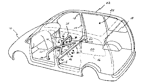
Figure 1 is a rear, perspective view of a motor vehicle including a bridge
assembly of a first embodiment of the invention;
Figure 2 is a rear, perspective view of a pair of seats supported above a
floor by
the first embodiment of the invention; and
Figure 3 is a rear, perspective view of a motor vehicle including a second
embodiment of the invention.
Detailed Description of the Preferred Embodiment
Referring to Figures 1 and 2, a motor vehicle 10 includes a pair of opposing B
pillars 12, 14 for providing structural reinforcement to sidewalk 16, 18. More
specifically, the B-pillars 12, 14 distribute side impact forces over the
sidewalk 16, 18 of
the motor vehicle 10. The B-pillars 12, 14 extend between upper ends 11, 13
and lower
ends 15, 17. The upper ends 11, 13 are fixedly secured to a roof 22 and the
lower ends
15, 17 are fixedly secured to a floor 20. The B-pillars 12, 14 extend between
the floor 20
and the roof 22. Together, the sidewalk 16, 18, the floor 20, and the roof 22
define a
passenger compartment 24.
A bridge assembly, generally shown at 26, includes a rear cross car beam 28
2

CA 02403319 2002-09-13
fixedly secured to the B-pillars 12, 14 to provide structural rigidity and
support thereto.
The rear cross car beam 28 defines a rear length 30 extending between a rear
driver end
32 and a rear passenger end 34. The rear cross car beam 28 is fixedly secured
to the B-
pillars 12, 14 at its rear driver 32 and rear passenger 34 ends by fasteners,
welds, or the
like so as to be spaced above the floor 20. More specifically, the rear cross
car beam 28
is secured to the two B-pillars 12, 14 at locations between the upper 11, 13
and lower 15,
17 ends.
The bridge assembly 26 also includes a front support structure, generally
shown at
35, spaced forward of the rear cross car beam 28 within the passenger
compartment 24.
In the first embodiment, the front support structure 35 is a front cross car
beam 36. The
front cross car beam 36 includes a plurality of support legs 38 extending
downwardly
therefrom. Each of the plurality of support legs 38 is fixedly secured to the
floor 20 to
support the front cross car beam 36 above the floor 20.
The front cross car beam 36 includes forward segments 37 spaced apart and
extending along the same line. It will be appreciated that the front cross car
beam 36 may
have various configurations depending upon motor vehicle design preferences.
For
example, the front cross car beam 36 may include a single forward segment 37
extending
across the entire passenger compartment 24 parallel to the rear cross car beam
28.
A crossing support, generally shown at 40, is fixedly secured to, and extends
above the floor 20 between, the rear cross car beam 28 and the front support
structure 35.
In the first embodiment, the crossing support 40 includes a plurality of cross
beams 42
fixedly secured to the rear 28 and front 36 cross car beams. In a preferred
embodiment,
each of the plurality of cross beams 42 is coplanar with the rear cross car
beam 28 while
extending outwardly from the rear cross car beam 28 at angles of approximately
forty-
five degrees and one hundred and thirty-five degrees, respectively. The angles
created by
the each of the plurality of cross beams 42 are supplementary angles. The
plurality of
cross beams 42 intersect or cross over each other. It should be appreciated
that the
plurality of cross beams 42 may extend outwardly from the rear cross car beam
28 at
angles other than those discussed above.
The extension of the plurality of cross beams 42 between the rear 28 and front
36
cross car beams allows the bridge assembly 26 to support one or more seats 46
3

CA 02403319 2002-09-13
thereabove. More specifically, the bridge assembly 26 supports the seats 46 by
having a
rearward portion 47 and a forward portion 49 thereof fixedly secured thereto
above the
floor 20. Thus, the bridge assembly 26 defines an undivided space 48
thereunder that
may be utilized for storage of items or as additional foot space for
passengers occupying
a rear seat. A center console 50 extending between the rear 28 and front 36
cross car
beams, and between the seats 46, may be integrated into the bridge assembly
26. A
bridge cover 51 may provide an aesthetically pleasing appearance.
The bridge assembly 26 creates a load path such that upon a side impact,
forces
are distributed from one of the B-pillars 12, 14 to the other B-pillar 12, 14.
The support
legs 38, which are secured to the floor 20 and the front cross car beam 36,
further
distribute the lateral load into the floor 20. Therefore, side impact forces
on the motor
vehicle 10 may be more evenly distributed through the bridge assembly 26,
which is
supported between the B-pillars 12, 14, and into the floor 20 and sidewalls
16, 18.
Refernng to Figure 3, wherein like primed reference numerals represent similar
elements as those described above, a second embodiment incorporates a support
plate 58
as the front support structure 35'. The support plate 58, spaced forwardly of
the rear
cross car beam 28', is fixedly secured to the floor 20'. The plurality of
cross beams 42'
extends between the support plate 58 and the rear cross car beam 28' parallel
to each
other. Thus, the plurality of cross beams 42' is supported above the floor 20'
by the
support plate 58 and the rear cross car beam 28'.
A panel 60 is supported above the floor 20' by the rear cross car beam 28' and
the
plurality of cross beams 42'. The panel 60 defines a plurality of mounting
bores 62
through which a fastener extends to fixedly attach one or more seats 46' to
the bridge
assembly 26'. Instead of a single panel, a plurality of panels may be utilized
with each of
the plurality of panels being supported by one or more of the plurality of
cross beams 42',
and the rear cross car beam 28'.
The invention has been described in an illustrative manner, and it is to be
understood that the terminology, which has been used, is intended to be in the
nature of
words of description rather than of limitation. Many modifications and
variations of the
present invention are possible in light of the above teachings. It is,
therefore, to be
understood that within the scope of the appended claims, the invention may be
practiced
4

<IMG>

Dessin représentatif
Une figure unique qui représente un dessin illustrant l'invention.
États administratifs

2024-08-01 : Dans le cadre de la transition vers les Brevets de nouvelle génération (BNG), la base de données sur les brevets canadiens (BDBC) contient désormais un Historique d'événement plus détaillé, qui reproduit le Journal des événements de notre nouvelle solution interne.

Veuillez noter que les événements débutant par « Inactive : » se réfèrent à des événements qui ne sont plus utilisés dans notre nouvelle solution interne.

Pour une meilleure compréhension de l'état de la demande ou brevet qui figure sur cette page, la rubrique Mise en garde , et les descriptions de Brevet , Historique d'événement , Taxes périodiques et Historique des paiements devraient être consultées.

Historique d'événement

Description Date
Demande non rétablie avant l'échéance 2008-09-15
Le délai pour l'annulation est expiré 2008-09-15
Réputée abandonnée - omission de répondre à un avis sur les taxes pour le maintien en état 2007-09-13
Inactive : Abandon.-RE+surtaxe impayées-Corr envoyée 2007-09-13
Demande publiée (accessible au public) 2003-03-13
Inactive : Page couverture publiée 2003-03-12
Inactive : CIB en 1re position 2002-11-12
Demande reçue - nationale ordinaire 2002-10-25
Inactive : Certificat de dépôt - Sans RE (Anglais) 2002-10-25
Lettre envoyée 2002-10-25

Historique d'abandonnement

Date d'abandonnement Raison Date de rétablissement
2007-09-13

Taxes périodiques

Le dernier paiement a été reçu le 2006-06-20

Avis : Si le paiement en totalité n'a pas été reçu au plus tard à la date indiquée, une taxe supplémentaire peut être imposée, soit une des taxes suivantes :

  • taxe de rétablissement ;
  • taxe pour paiement en souffrance ; ou
  • taxe additionnelle pour le renversement d'une péremption réputée.

Les taxes sur les brevets sont ajustées au 1er janvier de chaque année. Les montants ci-dessus sont les montants actuels s'ils sont reçus au plus tard le 31 décembre de l'année en cours.
Veuillez vous référer à la page web des taxes sur les brevets de l'OPIC pour voir tous les montants actuels des taxes.

Historique des taxes

Type de taxes Anniversaire Échéance Date payée
Enregistrement d'un document 2002-09-13
Taxe pour le dépôt - générale 2002-09-13
TM (demande, 2e anniv.) - générale 02 2004-09-13 2004-06-21
TM (demande, 3e anniv.) - générale 03 2005-09-13 2005-06-14
TM (demande, 4e anniv.) - générale 04 2006-09-13 2006-06-20
Titulaires au dossier

Les titulaires actuels et antérieures au dossier sont affichés en ordre alphabétique.

Titulaires actuels au dossier
INTIER AUTOMOTIVE INC.
Titulaires antérieures au dossier
COLIN G. NEALE
Les propriétaires antérieurs qui ne figurent pas dans la liste des « Propriétaires au dossier » apparaîtront dans d'autres documents au dossier.
Documents

Pour visionner les fichiers sélectionnés, entrer le code reCAPTCHA :


Pour visualiser une image, cliquer sur un lien dans la colonne description du document. Pour télécharger l'image (les images), cliquer l'une ou plusieurs cases à cocher dans la première colonne et ensuite cliquer sur le bouton "Télécharger sélection en format PDF (archive Zip)" ou le bouton "Télécharger sélection (en un fichier PDF fusionné)".

Liste des documents de brevet publiés et non publiés sur la BDBC .

Si vous avez des difficultés à accéder au contenu, veuillez communiquer avec le Centre de services à la clientèle au 1-866-997-1936, ou envoyer un courriel au Centre de service à la clientèle de l'OPIC.


Description du
Document 
Date
(aaaa-mm-jj) 
Nombre de pages   Taille de l'image (Ko) 
Dessin représentatif 2002-11-14 1 18
Revendications 2002-09-12 3 82
Dessins 2002-09-12 3 79
Abrégé 2002-09-12 1 17
Description 2002-09-12 5 213
Courtoisie - Certificat d'enregistrement (document(s) connexe(s)) 2002-10-24 1 109
Certificat de dépôt (anglais) 2002-10-24 1 161
Rappel de taxe de maintien due 2004-05-16 1 109
Rappel - requête d'examen 2007-05-14 1 115
Courtoisie - Lettre d'abandon (requête d'examen) 2007-11-25 1 165
Courtoisie - Lettre d'abandon (taxe de maintien en état) 2007-11-07 1 173