Note : Les descriptions sont présentées dans la langue officielle dans laquelle elles ont été soumises.
CA 02403404 2002-09-16
WO 01/69006 PCT/GBO1/01208
- 1 -
The present invention relates to building panels.
A variety of building panels are known. The present invention seeks
to improve over those panels.
According to the present invention there is provided a panel
comprising a sheet of insulating material sandwiched between two metal
sheets, the outside surface of one of the metal sheets comprising a plurality
of building block supports.
Building blocks, for example brick slips, may therefore be supported
on one side of the panel to give the appearance of a conventional brick wall.
The sheet of insulating material may comprise a sheet of foam
material. Where this is the case the sheet of foam material preferably has
a density of at least 15 Kg/m3 or 30Kg/m3, but less than 45Kg/m3 and may
comprise extruded polystyrene foam but could comprise polyurethane foam
or another suitable material. The foam material preferably has a sheer
modulus of at least 2500 KPa, but less than 16000 KPa, and particularly
about 8000 KPa. An example of another insulating material that may be
used is mineral wool.
The thickness of insulating material may be varied depending on the
level of insulation (U value) required.
The sheets of metal are preferably at least 0.3mm thick, more
preferably between 0.3 and 1 mm thick and particularly about 0.7mm thick.
CA 02403404 2002-09-16
WO 01/69006 PCT/GBO1/01208
_2_
They may comprise steel sheet, may be treated to prevent corrosion, for
example by galvanizing, and are preferably bonded to the sheet of insulating
material with an adhesive. A two part polyurethane adhesive is suitable.
The metal sheets are preferably substantially flat.
In an alternative arrangement the metal sheets could be positioned in
a jig and an insulating material, particularly an expanding foam material
such as a polyurethane foam material, injected between the two, and
allowed to harden so that it bonds to the metal sheets.
Preferably one or both faces of the sheet of insulating material
includes a plurality of spaced apart channels extending to at least one edge
of the sheet. Such channels facilitate the escape of air and solvent from
between the metal sheets and the insulating material during assembly,
resulting in better adhesion of the insulating material and metal sheets.
One or more stiffening members may be provided between the metal
sheets. These may comprise strips of material extending between the two
metal sheets. Plastics and glass reinforced plastics materials are suitable;
wood and metal could also be used. The stiffening members are preferably
bonded to both metal sheets. The stiffening members may divide the sheet
of insulating material into a number of separate pieces.
The building block supports may be formed separately to or unitarily
with one of the metal sheets. In one embodiment they are provided by a
moulded plastics sheet bonded to a metal sheet with an adhesive. Such a
CA 02403404 2002-09-16
WO 01/69006 PCT/GBO1/01208
-3-
plastics sheet is preferably corona arc discharge treated prior to bonding it
to the metal sheet. This improves adhesion of the plastics sheet to the
metal sheet. In another embodiment the metal sheet is pressed to form
supports. In another embodiment the metal sheet includes outwardly
projecting tabs formed by cutting and folding the sheet. An example of a
metal sheet including unitarily formed building block supports is described
in US 3533206.
Preferably a formation configured to engage with a similar formation
is disposed along at least one edge, and preferably along each of two
opposed edges, of the panel. This enables panels to be joined together,
particularly stacked on each other, to form larger panels. The formations
may each include both male and female cooperating parts. The formations
may include a seal operative to form a seal with another formation. The
formations preferably comprise glass fibre reinforced resin pulltrusions, but
could also comprise metal, plastics or reinforced plastics extrusions or
mouldings.
Where one or more edges of the panel are fitted with metal
formations it is preferable to take steps to reduce the effect of cold
bridging
brought about because the formation provides a path for transfer of heat
between opposite sides of the panel. In one embodiment this is achieved
by adhering a resin to the formation and removing a part of the formation
to provide a gap in the formation between opposite sides of the panel.
CA 02403404 2002-09-16
WO 01/69006 PCT/GBO1/01208
-4-
Formations comprised of plastics material are inherently better thermal
insulators than metal ones, so extra steps need not be taken to prevent cold
bridging when these materials are used.
The inclusion of metal sheets enables panels of greater strength than
conventional building block support panels to be produced. The panels may
therefore be used as structural components in buildings. Larger panels than
have conventionally been the case can be constructed and the requirements
of any supporting structure for them is reduced.
As the panels include an insulating layer they can be used to form
single walled structures, with an interior finish being applied to the metal
sheet facing the inside of the structure. Alternatively, panels could be used
to form the outside wall of a cavity walled structure. They can, in
particular,
be used to form the outer wall of a timber or steel framed building.
In order that the invention may be more clearly understood
embodiments thereof will now be described, by way of example, with
reference to the accompanying drawings of which:
Figure 1 is an exploded perspective view of part of a panel according to
the invention (without brick slips);
Figure 2 is a side view of two pulltrusions engaged with each other;
Figure 3 is a side view of an alternative embodiment of a pulltrusion;
Figure 4 is a side view of part of two panels according to the invention
engaged with each other;
CA 02403404 2002-09-16
WO 01/69006 PCT/GBO1/01208
-5-
Figure 5 includes three cross-sectional views through a panel according
to the invention mounted on a timber framed structure;
Figure 6 includes views similar to Figure 5 for a concrete structure;
Figure 7 includes views similar to Figure 5 for a steel structure;
Figure 8 is a perspective view of part of a timber framed building
including a panel according to the invention;
Figure 9 is a plan view of two panels according to the invention
mounted side to side; and
Figure 10 is a plan view showing how two panels according to the
invention are joined at right angles to each other.
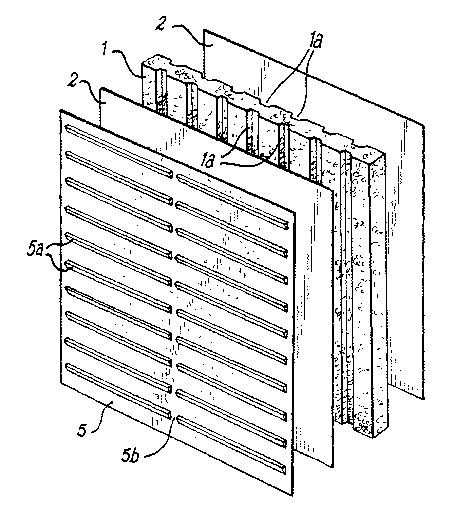
Referring to Figures 1 to 4 a panel comprises a 65mm thick sheet of
extruded polystyrene foam 1 of density about 35Kg/m3, sandwiched
between two zinc coated 0.7mm thick steel sheets 2. The steel sheets 2
are bonded to the foam sheet 1 with a two-part polyurethane adhesive 4.
A suitable adhesive is sold by Akzo-Nobel, under the designation 8243PUR.
The sides of the foam sheet 1 to which the steel sheets 2 are bonded
include a plurality of spaced apart substantially parallel channels 1 a
running
between opposite edges of the sheet 1. The purpose of the channels 1 a is
to allow any air or solvent trapped between the foam 1 and steel 2 sheets
to escape to ensure that a satisfactory bond is achieved between the
sheets.
A high impact polystyrene vacuum moulded building block support
CA 02403404 2002-09-16
WO 01/69006 PCT/GBO1/01208
g_
sheet 5 is bonded to the outside surface of one of the steel sheets 2 with
an adhesive 6. A similar adhesive as used to bond the steel sheets 2 to the
foam sheet 1 is suitable. Prior to bonding the building block support sheet
to the metal sheet 1 the building block support sheet is preferably corona
5 arc discharge treated. This results in better adhesion to the metal sheet 1.
The building block support 5 comprises a sheet having a series of
substantially parallel evenly paced apart projecting ledges 5a extending
laterally across its surface, but not all the way to the lateral edges of the
sheet. As such, when two panels are placed adjacent to each other there
is an upright gap in the ledges between the panels. One or more additional
gaps 5b are provided along the length of each ledge to allow any trapped
moisture to drain away. Having a gap in the ledges between panels helps
to negate the effect of any misalignment between panels, although this is
preferably avoided. The ledges themselves are provided by ribs of
substantially triangular cross-section, but with one side open as they are
formed by deforming a single sheet of material. Each rib has an upper
surface for supporting building blocks which extends substantially
perpendicularly outwardly from the plane of the sheet 5. The exposed
surface of the sheet, other than where there are blocks, includes a relief
pattern (not shown) to aid adhesion of building blocks thereto.
20mm thick brick slips 7 are supported on the ledges of the building
block support sheet 5, and bonded to the building block support with an
CA 02403404 2002-09-16
WO 01/69006 PCT/GBOI/01208
adhesive 8. A suitable adhesive is supplied by Honeywell Speciality Wax
and Adhesives Ltd under the designation Ralithane 810. The nominal height
of the brick slips 7 is 65mm, 5mm less than the distance between adjacent
ribs on the building block support. This allows for some tolerance in actual
brick slip height. The pitch of the ribs of the building block supports is
chosen to provide approximately 10mm of space between brick slips 7 on
adjacent rows. The brick slips 7 are similarly spaced apart along each rib.
The space between the brick slips is filled with mortar 8. The panel
therefore has the appearance of a conventional brick wall with 10mm
mortar beds. Other spacings could, of course, be chosen.
Glass fibre pulltrusions 9 are fitted to the upper and lower edges of
the panel. The steel sheets 2 extend adjacent to and are bonded to the
pulltrusions. Adhesive could, optionally, but not essentially, also be
introduced between the facing surfaces of the pulltrusion 9 and foam sheet
1. The pulltrusions 9 are formed by drawing a fibre matrix through a resin
bath and then through a heated die to form the desired cross-section. This
process is known and will therefore not be described further. The
pulltrusions 9 are generally L-shaped and each include a male 10 and a
female 11 formation shaped to engage with respective female and male
formations of a similar pulltrusion. The male formation 10 comprises a
projection, and the female formation 11 a slot. The bottom of the slot
includes a channel housing a resilient sealing member 12 operative to form
CA 02403404 2002-09-16
WO 01/69006 PCT/GBO1/01208
_g_
a substantially watertight seal with a male formation 10 received into the
slot. The pulltrusions 9 each include two cavities 13 running along their
length. This reduces the amount of material required to form the
pulltrusion. By virtue of their L-shaped cross-section two engaged
pulltrusions 9 also define a further cavity 14, which can accommodate a
bolt head as will become apparent below.
The pulltrusions 9 enable panels to be stacked one on the other.
When the pulltrusions 9 of two panels are engaged they prevent relative
lateral movement of, and establish a substantially watertight seal between,
the panels.
The lateral edges of the foam sheet 1 and pulltrusions 9 may
optionally include a slot running parallel to and approximately mid-way
between the steel covered faces of the panel. The position of this optional
slot is indicated by crosshatching in Figure 2 and broken lines 15 and
crosshatching in Figure 4. This slot facilitates joining of adjacent panels at
right angles to each other. This is described further below.
Figure 3 shows an alternative embodiment of a pulltrusion. It is
substantially similar to that shown in Figures 2 and 4 save that the female
formation includes inwardly projecting shoulders 16 on opposite sides
respectively which narrow the entry into the channel in the bottom of the
slot. The shoulders are arranged to be received into channels extending on
opposite sides of a resilient sealing member 17 to aid retention of the
CA 02403404 2002-09-16
WO 01/69006 PCT/GBO1/01208
_g_
sealing member 17 in the female formation.
The illustrated panels are intended to be used for construction of
buildings. The brick slip covered surface provides the outside wall of the
building. Inclusion of the foam sheet and use of pulltrusions gives the panel
a U-value of 0.35. Inclusion of the metal sheets gives considerable
strength.
In one building technique the panels are used to form the outside wall
of a cavity walled building. Figure 5 shows three cross-sections at different
heights through part of a wall of a timber framed building. The building
comprises a concrete foundation 18. Supported on the foundation is a
timber frame 19. Although not shown the frame would typically be boarded
over with wooden boards to increase its rigidity. Plasterboard (not shown)
is supported on the inside side of the wooden framework to provide inside
walls of the building. Panels according to the invention 20,20a of the type
illustrated in Figures 1,2 and 4 are mounted around the outside of and
spaced apart from the timber frame 19 to form the outside wall of the
building and a cavity between the panel 20 and frame 19.
A pulltrusion 9a is bolted to the concrete foundation 18 by means of
an expanding bolt 21 passing through the pulltrusion 9a into the concrete.
A layer of compressible packing material 22 is disposed between the
pulltrusion 90 and the concrete to compensate for any irregularities in the
surface of the concrete.
CA 02403404 2002-09-16
WO 01/69006 PCT/GB01/01208
- 10-
A pulltrusion 9b forming the lower edge of the panel 20 is engaged
with the pulltrusion 9a bolted to the foundation 18. The upper edge of the
panel 20 includes a further pulltrusion 9c. This pulltrusion 9c is bolted to
the timber frame 18 by means of a bolt 23 extending laterally through the
pulltrusion 23 and into the timber frame 19. A spacer 24 is disposed on
bolt 23 between the pulltrusion 9c and the frame 19 to space apart the
panel 2 and frame. A second panel 20b is supported on the first panel 20a.
The lower edge of the second panel 20b includes a pulltrusion 9d which is
engaged with pulltrusion 9c. The upper edge of the second panel 20b also
includes a pulltrusion 9d which is bolted to the frame 19 in the same
manner of the pulltrusion 9b at the top of the first panel 20a.
Any number of panels could be stacked, as required. The weight of
the panels is taken by the concrete foundation 18 and the timber frame 19
supports the panel against lateral forces, for example due to wind.
Figure 6 shows how panels 20c,20d may be mounted on a concrete
wall or pillar 25. The lower panel 20c is supported on a pulltrusion 9e
which is supported on and bolted to an L-shaped bracket 26 which is, in
turn, fastened to the concrete wall or pillar 25 by way of an expanding bolt
27 and nut 28. The laterally projecting arm of the L-shaped bracket 26 on
which the pulltrusion 9e is supported includes a drainage aperture 30, to
allow any water accumulating between the wall or pillar 25 and panels 20c,
20d to drain away.
CA 02403404 2002-09-16
WO 01/69006 PCT/GBO1/01208
- 11 -
The top of the panels 20c and 20d are fastened to the concrete wall
or pillar by way of expanding bolts 31 with spacers 32, in a similar manner
to the arrangement shown in Figure 5.
Figure 7 shows how panels may be mounted on an upright steel H-
girder, such as might be used in the construction of a portal framed
building. The method is the same as that shown in Figure 6, save that the
bolts used to fasten the L-shaped bracket and protrusions to the pillar are
of the ordinary rather than expanding type.
Figure 8 shows how panels are used to form a building. The building
comprises a timber frame 33 supporting wooden panels 34 forming a stud
wall. Brick slip faced panels 35 of the type shown in Figures 1,2 and 4 are
supported as shown in Figure 5 spaced around the outside of the stud wall
to leave a cavity 36. A window opening 37 is provided by an aperture cut
in the panel 35 and a corresponding aperture in the adjacent stud wall. A
cavity closer 38 is fitted around the periphery of the aperture 37. A further
cavity closer 39 is fitted at the top of the cavity between the panel 35 and
stud wall.
As described it is envisaged that two or more panels are stacked one
on the other to form the walls of buildings. Depending upon the size of the
panels used and the size of buildings it is desired to construct two or more
panels may need to be installed side to side. Figure 9 shows two such
panels 39. These are mounted adjacent each other so that there is a small
CA 02403404 2002-09-16
WO 01/69006 PCT/GBO1/01208
- 12-
clearance between their respective ends. The space between the panels is
filled with a length of compressible polyurethane foam 40. The foam 40 is
formed with a circular cross-section with a diameter greater than the
clearance between the panels. The foam is thus deformed when the panels
are brought towards each other, effecting a seal. The remaining space
between the foam 40 and the surface of the panels 39 is filled with mastic
41 to provide a weatherproof finish.
Corner joints between panels may be effected as shown in Figure 10.
A first panel 42 is provided with an upright slot 43 in one lateral edge, as
indicated by broken lines 15 in Figure 4. The lateral edge of a second panel
46, disposed substantially at right angles to the first panel, is capped with
steel sheet 44 bonded to the panel. A length of L-section glass reinforced
plastic (grp) 45 is bonded along the edge of the face of the second panel 46
facing the edge of the first panel 42 so that the projecting part of the grp
section 45 is directed into the slot 43 in the first panel 42.
The joint is completed by applying a suitable mastic to the grp section
45 and inserting it into the slot 43 bringing the two panels 42,46 together.
In another embodiment of a panel one of the two metal sheets 2
includes formations for the support of blocks. This renders the moulded
plastics sheet 5 superfluous. One of the metal sheets could be pressed to
form it into the shape of the plastic panel or, alternatively, a number of
outwardly extending tabs could be formed in the manner described in US
CA 02403404 2002-09-16
WO 01/69006 PCT/GBO1/01208
- 13-
3533206.
The above embodiments confer a number of advantages over
conventional insulated cladding panels and building block support panels.
The use of metal sheets and high density foam material enables the panels
to have considerably increased strength over conventional panels which
allows them to become a structural member of a building of which they
form part. The requirements of any supporting structure, for example a
steel or wooden framework conventionally used to support cladding panel
is considerably reduced or eliminated. Panels according to the invention are
generally much lighter in weight than conventional brick walls. This reduces
the requirements of any foundation intended to support them.
The inclusion of metal sheets also enhances the integrity of the
panels. It is, for example, more difficult to pierce a hole through a panel
including a steel sheet, than through a conventional brick wall.
The above embodiments are described by way of example only, many
variations are possible without departing from the invention.