Note : Les descriptions sont présentées dans la langue officielle dans laquelle elles ont été soumises.
CA 02404437 2002-09-27
WO 01/72620 PCT/ITO1/00145
"REWINDING MACHINE AND METHOD FOR WINDING UP ROLLS OF
WEBLIKE MATERIAL ON EXTRACTABLE MANDRELS"
DESCRIPTION
Technical Field
The invention relates to a rewinding machine, in other words a
machine for the production of rolls of weblike material, for example - but not
exclusively - rolls of paper, tissue paper or the like, for the subsequent
production of small rolls of toilet paper, kitchen towel or other products in
roll
form.
More specifically, the present invention relates to a rewinding
machine, preferably of the type known as peripheral or superficial, that is to
say where the roll being formed is mairttained in rotation by means of contact
with peripheral winding-up members, such as rollers, belts or equivalent
elements. Furthermore, the present invention relates to a rewinding machine
having extractable mandrels, that is to say wherein, at the completion of
winding-up, the mandrels are extracted in order to obtain a roll having no
mandrel or central winding-up core.
The invention also relates to a method of winding up for the
production of rolls of weblike material, typically - but not exclusively -
rolls of
paper, tissue paper or the like.
State of the Art
In numerous sectors of industry, and in particular in the paper
converting industry, it is frequently necessary to produce rolls of wound-up
weblike material, for example rolls of paper, tissue paper or the like; in
other
technological sectors, the need arises to produce rolls of plastic film,
fabric,
nonwoven fabric and other materials in web form.
Especially in the production sector of tissue paper articles, such
as rolls of toilet paper, kitchen towel or similar products, from large-
diameter
reels, produced in paper mills, rolls or logs are produced having a diameter
equal to the diameter of the product intended for the end consumer and axial
lengths greater than those of the finished article. These rolls or logs are
subsequently cut orthogonally to their axis to produce the small rolls
intended
CA 02404437 2002-09-27
WO 01/72620 PCT/ITO1/00145
-2-
for consumption.
For the production of rolls of this type, use is commonly made of
rewinding machines of the type known as peripheral, where the roll being
formed is maintained in rotation and the weblike material is fed by means of
rotating members or other moveable members which are in surface contact
with the exterior of the roll being formed. Examples of rewinding machines are
described and illustrated in US-A-4 723 724, US-A-4 856 725,
US-A-4 828 195, US-A-4 962 897, US-A=4 487 377, US-A-4 931 130,
US-A-5 248 106, US-A-5 368 252, GB-A-2 105 688 and WO-A-9 421 545.
According to another technology, the rolls are wound up on
motor-driven mandrels. This is referred to as central winding. Examples of
this
technology are described in US-RE-2 835 3, US-A-3 430 881,
US-A-3 532 572, US-A-3 552 670.
Normally, the rolls are produced on a tubular cardboard core
which then remains permanently within the roll and is cut together with the
wound-up weblike material, so that a piece of tubular core remains in each of
the individual rolls intended for the end consumer.
Special methods also exist for winding up rolls without a central
core, where the.finished roll takes on the appearance of a compact cylinder
completely filled with weblike material. Rewinding machines which operate in
accordance with this principle are described in US-A-5 639 046,
US-A-5,690 296, US-A-5,839,680, US-A-5 538 199.
Winding-up systems have also been studied in which the
weblike material is wound up on a central core or mandrel to form the roll
from
which the mandrel is subsequently extracted and recycled. This system
makes it possible to operate with winding-up principles substantially similar
to
those used for winding up on cardboard cores, but eliminates the need to
produce and consume tubular cardboard cores, with a consequent saving of
materials and a reduction in the bulk of the machinery, in that the need for
what are known as the "tube-makers", in other words the machines that
produce the cardboard cores from strips of cardboard, is eliminated. The
mandrels extracted from the finished rolls are recycled from the extraction
CA 02404437 2002-09-27
WO 01/72620 PCT/ITO1/00145
-3-
zone, located downstream of the rewinder, to the entry of the rewinder.
In this way, it is possible to carry out continuous high-speed
production with a limited number of mandrels.
In order to facilitate extraction and achieve other advantages in
terms of reduction of bulk and ease of manipulation, it has been suggested
that the extractable mandrels should be produced in two parts, each of which
is extracted from the appropriate end of the finished roll. A machine and a
method of this type are described in WO-A-99/42 393.
When the rolls are formed on extractable mandrels, appropriate
measures have .to be taken to ensure that the initial length of the weblike
material adheres to the outer surface of the winding-up mandrel. These
measures have to permit easy subsequent extraction of the mandrel once
winding-up has been completed. To this end, use may be made of pneumatic
systems, air blowers, electrostatic charges or the like which attract the free
length to and maintain it on the surface of the mandrel, their action ceasing
at
a subsequent stage of the winding-up cycle.
Systems have also been examined in which the outer surface of
the mandrel is soaked with water, which should provide a sufficient adhesive
action for the initial free length of the weblike material which is being
wound
up. The water is absorbed by the weblike material in the subsequent phase of
winding-up, thus permitting the subsequent extraction of the mandrel from the
finished roll.
The systems currently used to anchor the free initial length of
the weblike material on the extractable mandrel are not always satisfactory,
in
that they can be used only with certain types of material, or because they
provide an adhesive effect that is not always reliable, especially at high
production speeds, so that they enforce a reduced speed.
Objects and Summary of the Invention
It is an object of the present invention to provide a rewinding
machine and a winding method, in particular and preferably (but not
exclusively) of the peripheral type on extractable winding-up mandrels, which
makes it possible to achieve an effective and reliable anchoring of the free
CA 02404437 2002-09-27
WO 01/72620
PCT/ITO1 /00145
-4-
length of the weblike material on the mandrel, without obstructing or
otherwise
causing problems in the subsequent phases of extraction of the mandrel from
the finished roll.
This and further objects and advantages, which will become
apparent to persons skilled in the art from reading the text that follows, are
substantially achieved with a rewinding machine for the production of rolls of
weblike material, comprising: a system of winding up on winding-up mandrels
for the formation of said rolls; an extractor for separating the mandrels from
the respective rolls formed thereon and in which is provided at least one
washing device for washing said mandrels between the separation from the
rolls and the start of winding-up.
When a rewinding machine with central winding-up is used, the
mandrels are moved by a revolving turret or the equivalent to various
stations,
which include an adhesive application station, a winding-up station and a
station for drawing the roll or log off the mandrel. In this case, the washing
means may be disposed in a manner such as to operate along the path of the
mandrels between the station for drawing off the roll and the station for
application of the adhesive, or in one of those stations. They may comprise,
for example, brushes, pads or the like which pass along the axial course of
the mandrel. Alternatively, they may comprise a washing box having a tubular
chamber (possibly subdivided into two parts) within which the mandrel slides.
Preferably, however, the invention is embodied on a peripheral
rewinding machine. In this case, advantageously, a recirculating path for the
mandrels is provided between an extractor, which extracts the mandrels from
the finished rolls, and a feeder, which inserts them into a winding-up cradle.
The washing means are disposed in an appropriate position along the path of
the mandrels.
The provision of washing of the mandrels extracted from the
rolls makes it possible, first, to eliminate from the surface of the mandrels
any
residues of paper or other material that may continue to adhere to the
mandrel after extraction.
The presence of the washing system makes it possible, as a
CA 02404437 2002-09-27
WO 01/72620 PCT/ITO1/00145
-5-
particular advantage, to use an adhesive to cause the initial free length of
the
weblike material to adhere reliably and quickly to the mandrel at the start of
the winding-up of each roll. Any residue of adhesive on the extracted and
recycled mandrel can be removed by means of the washing system.
The washing system makes it possible to use extractable
mandrels in a traditional rewinder, in other words one designed to operate
with tubular cardboard cores and the use of adhesive. It is thus possible to
convert existing machines with minor modification operations. It is also
possible to produce machines that can operate either with extractable
mandrels or with tubular cores of cardboard (or other material) intended to
remain within the finished product.
This is not possible in the absence of a washing system, since in
that case debris would accumulate on the extractable mandrels.
It is not, however, necessary for the mandrels to be washed
during each winding-up cycle. It would be possible, for example, to provide
for
washing every "N" winding-up cycles, where "N" depends, for example, on the
type of adhesive and of weblike material.
Washing may take place by means of a washing fluid, for
example water or water with added detergents, or even by means of a vapour,
for example saturated steam, or by means of any other appropriate (liquid or
gaseous) fluid.
The adhesive is preferably applied to the mandrel before
insertion thereof into the zone where it comes into contact with the weblike
material. However, the possibility is not ruled out that the adhesive is
applied
to the weblike material in the zone thereof intended to come into contact with
the winding-up mandrel.
The washing device may be produced in various ways. For
example, provision may be made to unload the mandrels into a tank
containing a washing liquid, for example even ordinary water, with the
possible addition of a detergent or a solvent. A stirrer may be provided to
cause movement of the mandrels in the tank and facilitate the removal of the
debris and residues of adhesive. Alternatively, brush means or other
CA 02404437 2002-09-27
WO 01/72620 PCT/ITO1/00145
-6-
mechanical means may be provided which act on the surface of the mandrels
located in the tank. From here, the mandrels can be extracted and transported
into the winding-up zone, with or without a previous drying phase.
In general, the mandrels may be produced in a single piece or in
two pieces that can be coupled and uncoupled. Washing may be performed
either on the mandrels in a single piece or on the mandrels in two pieces, or
possibly on the two separate pieces which are subsequently coupled or
placed side by side (after washing) to form the mandrel. The possibility is
not
ruled out that the mandrels are produced in more than two pieces. When the
pieces into which the mandrel is subdivided are washed separately, two
washing devices may be provided, or a single washing device may be
provided in which the various parts into which the mandrels are subdivided
come together to be washed.
According to a particularly advantageous embodiment of the
invention, the washing device comprises at least one tubular washing
chamber through which the mandrels or parts thereof are passed and in which
washing members are disposed. These washing members may be of various
types and are preferably disposed in a circular arrangement to act on the
entire surface of the mandrels or parts of mandrels which pass through the
tubular chamber. For example, brushes or washing pads of annular shape
may be provided, if appropriate associated with dispensers for a liquid or
other washing fluid disposed upstream or in the same position as the brushes
or pads. Preferably, however, the washing members are produced in a
manner such as to have no mechanical contact with the surface of the
mandrels or parts of mandrels. In a particularly advantageous embodiment,
the latter comprise a series of nozzles which spray a liquid under pressure or
blow a gaseous medium. In this way, no friction force is exercised on the
mandrels or mandrel parts which could make it difficult for them to move
forward. The nozzles may even be oriented in a manner such that the jet
generated thereby helps to drive the mandrels or parts thereof forward. The
possibility is not ruled out that the washing means are of the contact type,
but
equipped with a movement system, in a manner such as to generate a thrust
CA 02404437 2002-09-27
WO 01/72620 PCT/ITO1/00145
_7_
in the forward direction of the mandrels. However, a solution of this type is
more complex and less efficient from the standpoint of removal of the debris
from the surface of the mandrels.
Although as a matter of principle it is possible to introduce the
washed mandrels into the rewinding machine even without drying them, in
particular when the washing fluid is a liquid, according to a preferred
embodiment of the invention drying systems are provided which may be
disposed, for example, within the chamber in which the mandrels or parts
thereof pass. The drying system may comprise mechanical members, for
example of absorbent material, which touch the surface of the mandrels or
parts thereof. Preferably, however, for drying as well, a system is preferred
that does not touch the surface of the mandrels, for example a suction
member acting on the surface of the mandrels or parts of mandrels passing
through the washing chamber.
Further advantageous possible features of the machine and
method according to the invention are indicated in the appended claims and
will be described in detail with reference to a possible form of embodiment.
Brief Description of the Drawincts
The invention will be better understood from the description and
the attached drawing, which shows a practical, non-limiting example of said
invention. In the drawing:
Fig. 1 shows a diagrammatic lateral view of a rewinding machine
according to the invention;
Fig. 2 shows a plan view along the line II-I I in Fig. 1;
Fig. 3 shows a local lateral view along the line III-III in Fig. 1 of
the system for extracting a portion of mandrel;
Figs. 4a and 4b show an enlarged local view along the line IV-IV
in Fig. 1;
Fig. 5 shows a section along the line V-V in Fig. 4;
Fig. 6 shows a lateral view of one of the two washing systems
for the mandrels;
Fig. 7 shows a frontal view along the line VII-VII in Fig. 6; and
CA 02404437 2002-09-27
WO 01/72620 PCT/ITO1/00145
-g_
Fig. 8 shows a longitudinal section along the line VIII-VIII in
Fig. 7.
Detailed description of a preferred embodiment of the invention
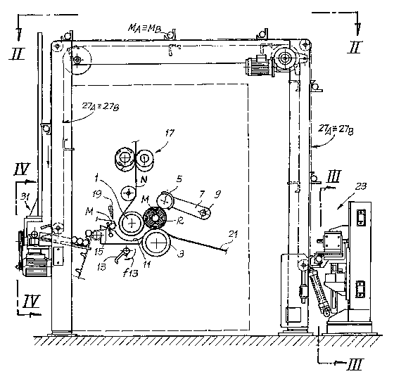
Figs. 1 and 2 show, generally and diagrammatically, a rewinder
according to the invention, confined to the general parts of the machine. The
winding-up members are shown indicatively, being confined to what is
necessary for an understanding of the invention. More specifically, in the
embodiment shown, the winding-up members are of the peripheral type with
three winding-up rollers designated 1, 3 and 5. The rollers 1, 3 and 5 define
a
winding-up zone where the rolls or logs R are formed. The winding-up roller 5
is mounted on an arm 7 pivoted at 9 and oscillating in order to follow the
growth of the roll R being formed. Between the winding-up rollers 1 and 3 a
nip is defined through which passes the weblike material which is wound up
on the roll R when the latter is in contact with the trio of rollers 1, 3 and
5. The
weblike material, designated N, is fed around the first winding-up roller 1.
In front of the nip formed by the winding-up rollers 1 and 3 is
disposed a rolling surface 11 formed by a comb-type structure and defining,
together with the cylindrical surface of the winding-up roller 1, a channel
for
the insertion and advancement of the winding-up mandrels. Below the rolling
surface 11 is a means 13 for severing the weblike material, which rotates at
appropriate times about its own axis in the direction of the arrow f13 to
perform the severing of the weblike material and create the final length of
the
roll R and the initial length which will adhere to the subsequent winding-up
mandrel which is being inserted into the machine.
The winding-up mandrels are introduced into the machine by
means of a revolving feeder 15 whose movement is synchronized with that of
the severing means 13, which in turn is synchronized with the movement of a
perforator unit 17, in a manner such that the weblike material is severed
along
one of the lines of perforation generated by the perforator 17.
The winding-up means, the means of introducing the winding-up
mandrels and the means of severing the weblike material briefly described
here are substantially equivalent to those described in greater detail in
CA 02404437 2002-09-27
WO 01/72620 PCT/ITO1/00145
_g_
WO-A-94/21 545, to which reference is made for further details of the
functioning of the winding-up means, the means for severing the weblike
material and the perforation means. The structure of the winding-up means
can, of course, be different from that briefly described above, since in
general
the present invention can be implemented with any peripheral system of
winding-up on a tubular winding-up core or mandrel.
The winding-up mandrels, designated M, are provided with
gluing points, gluing taking place by means of nozzles or guns for the
application of adhesive, designated 19 and, disposed in series along the
transverse extent of the machine, so that a sufficient quantity of adhesive is
distributed over the entire axial extent of each mandrel M which is presented
for introduction into the winding-up zone so as to cause the initial free
length
of the weblike material to adhere in order thus to commence the winding-up of
a roll. The adhesive may be applied continuously or by zones or at isolated
points.
The rolls R formed in the winding-up zone described above are
caused to roll on a chute 21 until they arrive at an extraction station,
generally
designated 23, where the individual mandrels M are extracted by means of
extractor members which will be described in greater detail with reference to
Fig. 3.
The mandrels are produced, in a manner known per se
(see WO-A-99/42 393) in two portions which are coupled before the
winding-up begins thereon and which are then each extracted from one end
of the roll R in the extraction station 23 to be recycled into the insertion
zone.
As can be seen in the plan view of Fig. 2, the extraction station
possesses two extractors 25A and 25B disposed on the two sides of the
machine, which extract the two portions MA and MB of which the winding-up
mandrels M are formed. The two portions MA and MB of the mandrels are
then removed from the extraction station 23 by means of two chain conveyors
27A and 27B (see, in particular, Fig. 1 ) which transfer the individual
mandrel
portions to a mandrel washing and recoupling zone, designated 31 and
disposed upstream of the winding-up means 1, 3 and 5.
CA 02404437 2002-09-27
WO 01/72620 PCT/ITO1/00145
-10-
The conveyors 27A and 27B, which in the example illustrated
are formed by chains bearing cradles appropriately shaped to retain mandrel
portions MA, MB of various sizes, may be replaced by other means of
recirculating the mandrels, for example chutes or rolling surfaces extending
laterally to the rewinding machine.
The two extractors 25A and 25B which provide for the extraction
from the finished roll of the two mandrel portions MA and MB have a
symmetrical structure, and only one of them will be described in more detail
with reference to Fig.3. The extractor possesses a support 33 with a
horizontal sliding guide 35, along which moves a carriage 37 whose
alternating movement in the direction of the double arrow f37 is controlled by
a motor drive 39yby means of appropriate transmission members, represented
in the example shown in the drawing by a belt 41 linked in an intermediate
position to the carriage 37.
The position of the sliding guide 35 may be adjusted in the
vertical direction according to f35 to adapt to the various sizes of rolls
that
may be produced by the rewinding machine.
The carriage 37 bears, mounted to overhang, a jaw 43 which
engages the portions MA, MB forming the mandrels M in line with the
respective end thereof projecting from the roll R. The jaw 43 has two
expansion members 45 which engage in annular projections MR produced
within the cylindrical surface of the mandrels M.
By means of appropriate control means, the expansion
members 45 can be moved apart and brought together to engage on and
disengage from the portion MA or MB of the mandrel M. When the jaw 43 is
engaged on the portion MA or MB of the mandrel M on which the roll R is
formed, the left-to-right movement in Fig. 3 of the carriage 37 causes the
extraction of the mandrel portion MB from the roll R, the latter being
maintained in an axial position by means of a ledge 49 provided in the
extraction zone 23.
Fig. 3 shows in broken lines the final position, designated 43X,
which is assumed by the jaw 43 when the mandrel portion MB is completely
CA 02404437 2002-09-27
WO 01/72620 PCT/ITO1/00145
-11 -
drawn out from the roll R. In this position, the expansion members 45 have
been released by the mandrel portion MB, which is thus supported on two
intermediate supports 51 and released by the jaw 43.
Once relinquished on the support 51, the mandrel portion MB
can be picked up by the cradles provided on the respective conveyor 27 to be
carried into the washing and recoupling zone 31.
The washing and recoupling zone 31 is illustrated in detail in
Figs. 2 and 4 to 8. In this zone, movement devices are provided, for example
in the form of four conveyors, represented in the example shown by an equal
number of aligned conveyor belts, designated 53A, 55A and 53B, 55B. The
conveyor belts 53A, 55A and 53B, 55B are disposed symmetrically relative to
a vertical plane of symmetry of the production line. They are controlled by a
common motor 57 by means of a pulley 59 and a belt 61. With an appropriate
arrangement of transmission pulleys and belts, generically designated 63A
and 63B, the motor 57 controls the movement of the conveyor belts 53A and
55A in the direction of the arrow fA and, in the opposite direction, in the
direction of the arrow fB, the conveyor belts 53B and 55B.
With this arrangement, the mandrel portions MA and MB which
are unloaded from the conveyors 27A and 27B onto the conveyor belts 53A
and 53B are moved together axially in pairs and moved into abutment against
a pair of sections 71 A and 71 B placed in a central position relative to the
conveyor belts 53A, 53B and 55A, 558. From here, the two mandrel portions
MA and MB are unloaded, by virtue of the curvature of the sections 71 A and
71 B, and caused to roll on inclined bars 73 until they abut against the
chains
77 of a conveyor.
From here, the individual mandrel portions MA, MB are taken by
means of a chain conveyor 77 which bears pick-up members 79 and are
transferred in the direction of the arrow f77 toward the adhesive applicator
nozzles 19 (see Fig. 1).
In an intermediate position along the path of the mandrel
portions MA, MB from the conveyor belts 53A, 55A and 53B, 55B toward the
nozzles 19, axial thrust means are provided which bring about the recoupling
CA 02404437 2002-09-27
WO 01/72620 PCT/ITO1/00145
-12-
of the portions MA and MB to form a complete mandrel M which is then
inserted into the winding-up zone of the rewinding machine. These coupling
means may comprise, for example, pneumatic, hydraulic or other cylinders,
for example converging, shaped lateral walls against which the outer ends of
the portions MA, MB of the mandrels are forced during their advance. The
thrust exercised by the lateral walls causes the two mandrel portions to be
axially moved together and coupled. In a manner known per se, the ends of
the mandrel portions that are intended to be coupled may be appropriately
shaped, for example with male and female coupling surfaces, of frustoconical
or other shape. It is also possible to provide for the two portions merely to
be
placed side by side.
As can be seen in particular in Figs. 2 and 4, two washing units
designated 81 A and 81 B are disposed between the conveyors 53A and 55A
on the one hand and between the conveyors 53B and 55B on the other hand.
The two washing units 81 A and 81 B are substantially
symmetrical, and only the unit 81 A will be described below, being shown in
more detail in Fig. 8. This possesses a tubular chamber 83, in other words a
chamber with a through axial aperture. The chamber 83 is defined by a first
portion 83A delimited by a collar 85 along whose annular extent dispenser
nozzles for a washing liquid are disposed.
In the example shown in the figure, five dispenser nozzles 85
are provided, uniformly disposed along the annular extent of the device. The
portion 83A of the tubular chamber is followed by a portion 83B, delimited by
a sleeve 87. The portion 83B is connected, via an aperture in the sleeve 87,
to a suction duct 89. A suction space is thus formed, through which the
mandrel portions pass. The mandrel portion MA enters into the tubular
chamber 83 in the direction of the arrow F shown in Fig. 8 and exits from the
opposite part having passed through the two portions 83A and 84B of the
tubular chamber 83. The inlet aperture of the tubular chamber 83 is delimited
by a ring 90, while the outlet aperture is delimited by a ring 92.
The nozzle-type dispensers 85 are connected by means of
flexible pipes (not shown) to a pump or other means of dispensing washing
CA 02404437 2002-09-27
WO 01/72620 PCT/ITO1/00145
-13-
liquid under pressure, while the suction duct 89 is connected to a vacuum
source. With this arrangement, the passage of the mandrel portions through
the tubular chamber 83 causes the entire surface of the mandrel portion to be
subjected, during movement in the direction of the arrow F, to the jets of
washing liquid generated by the nozzle-type dispensers 85. The surface is
subsequently dried by means of the suction generated via the suction duct 89.
The rings 90, 92 provide a guide for the portions MA and MB and have a size
such as to permit the entry of air which performs the drying.
The machine hitherto described operates as follows.
Individual mandrels M formed from portions MA and MB,
coupled or placed side by side axially, are introduced at appropriate moments
into the channel defined by the first winding-up roller 1 and by the rolling
surface 11 after having received on their own surface a sufficient quantity of
adhesive applied by means of the sprayer nozzles 19 or in another suitable
manner, for example by means of pads, by means of dipping rollers from a
tank or other means. From this time until the completion of the winding-up of
the individual roll R on the mandrel M, the operation of the rewinding machine
is identical to that of the conventional rewinding machines and in particular
(in
the example shown) to the operation described in WO-A-94/21 545.
The individual rolls R formed are unloaded into the extraction
station 23, where the two jaws (one of which is shown in Fig.3 and
designated 43 therein) grip from opposite sides the projecting ends of the
portions MA and MB forming each mandrel and cause their extraction. The
two portions MA and MB are carried by the extraction jaws 43 in alignment
with the two lateral conveyors 27A and 27B which pick up the mandrel
portions MA and MB and convey them to the entry zone of the rewinding
machine, eventually carrying them onto the conveyor belts 53A and 53B.
Here, by means of movement of the conveyor belts 53A, 55A
and 53B, 55B, each mandrel portion MA, MB is caused to pass through the
respective washing unit 81 A, 81 B. By virtue of the configuration of the
washing unit 81A, 81 B described above, any residues of adhesive or other
impurities to be found on the cylindrical surface of the mandrel portions MA
CA 02404437 2002-09-27
WO 01/72620 PCT/ITO1/00145
-14-
and MB are removed, so that the mandrel portions MA and MB are completely
cleaned and dried when situated on the conveyor belts 55A and 55B. From
here, they are again conveyed into the entry zone of the channel defined by
the winding-up roller 1 and by the rolling surface 11, having first been
axially
coupled to one another, in order to begin a new winding-up cycle.
It is understood that the drawing shows only a simplification,
given solely as a practical demonstration of the invention, said invention
being
capable of being varied in shapes and configurations without thereby
departing from the scope of the idea underlying said invention.