Sélection de la langue

Search

Sommaire du brevet 2405184 

Énoncé de désistement de responsabilité concernant l'information provenant de tiers

Une partie des informations de ce site Web a été fournie par des sources externes. Le gouvernement du Canada n'assume aucune responsabilité concernant la précision, l'actualité ou la fiabilité des informations fournies par les sources externes. Les utilisateurs qui désirent employer cette information devraient consulter directement la source des informations. Le contenu fourni par les sources externes n'est pas assujetti aux exigences sur les langues officielles, la protection des renseignements personnels et l'accessibilité.

Disponibilité de l'Abrégé et des Revendications

L'apparition de différences dans le texte et l'image des Revendications et de l'Abrégé dépend du moment auquel le document est publié. Les textes des Revendications et de l'Abrégé sont affichés :

  • lorsque la demande peut être examinée par le public;
  • lorsque le brevet est émis (délivrance).
(12) Demande de brevet: (11) CA 2405184
(54) Titre français: SYSTEME DE GESTION D'ENERGIE IMPLANTABLE ET METHODE CORRESPONDANTE
(54) Titre anglais: IMPLANTABLE ENERGY MANAGEMENT SYSTEM AND METHOD
Statut: Réputée abandonnée et au-delà du délai pour le rétablissement - en attente de la réponse à l’avis de communication rejetée
Données bibliographiques
(51) Classification internationale des brevets (CIB):
  • A61N 01/378 (2006.01)
  • A61N 01/08 (2006.01)
  • H01M 10/46 (2006.01)
  • H01M 10/48 (2006.01)
(72) Inventeurs :
  • VALENTA, HARRY L., JR. (Etats-Unis d'Amérique)
  • PROBST, JOSEPH M. (Etats-Unis d'Amérique)
(73) Titulaires :
  • WILSON GREATBATCH TECHNOLOGIES, INC.
(71) Demandeurs :
  • WILSON GREATBATCH TECHNOLOGIES, INC. (Etats-Unis d'Amérique)
(74) Agent: BLAKE, CASSELS & GRAYDON LLP
(74) Co-agent:
(45) Délivré:
(22) Date de dépôt: 2002-09-25
(41) Mise à la disponibilité du public: 2003-03-25
Licence disponible: S.O.
Cédé au domaine public: S.O.
(25) Langue des documents déposés: Anglais

Traité de coopération en matière de brevets (PCT): Non

(30) Données de priorité de la demande:
Numéro de la demande Pays / territoire Date
60/324,708 (Etats-Unis d'Amérique) 2001-09-25

Abrégés

Abrégé anglais


An implantable energy supply system having at least two
cells is disclosed. The system may have a switch with
a first state in which the cells are electrically
connected to a load, and a second state in which each
cell is electrically connected with its own charger.
A measurer may be electrically connected to a cell
to provide an indication of the charge on the cell.

Revendications

Note : Les revendications sont présentées dans la langue officielle dans laquelle elles ont été soumises.


-8-
What is claimed is:
1. An implantable energy supply system, comprising:
a first cell and a second cell;
a switch having a first state in which the cells
are electrically connected to a load, and a second state
in which the first cell is electrically connected to its
own charger;
a measurer electrically connected to the first cell
and providing an indication of the charge on the first
cell.
2. The energy supply system of claim 1, further
comprising a logic circuit electrically connected to the
measurer and capably of providing signals to disconnect
the load from the cells when the first cell requires
charging.
3. The energy supply system of claim 1, further
comprising a logic circuit electrically connected to a
cell temperature sensor and capable of providing signals
to disconnect the load from the cells when the first
cell has a high temperature.
4, The energy supply system of claim 3, wherein the
logic circuit includes a microprocessor,

-9-
5. The energy supply system of claim 3, wherein the
logic circuit includes an integrated circuit.
6. The energy supply system of claim 1, wherein the
indication of the charge on the first cell is a quantity
of energy delivered to the first cell.
7. The energy supply system of claim 7, wherein the
indication of the charge on the first cell is determined
from a voltage differential across terminals of the
cell.
8. The energy supply system of claim 1, wherein the
indication of the charge an the first cell is determined
from a rate of current delivered to the first cell.
9. The energy supply system of claim 1, further
comprising a transformer having a receiver to accept
energy, and provide electricity to the first cell.
10. The energy supply system of claim 9, wherein the
energy includes radio waves.

-10-
11. The energy supply system of claim 1, further
comprising a temperature monitor joined to one of the
cells.
12. The energy supply system of claim 11, wherein the
temperature monitor is capable of providing a high
temperature signal when a temperature of the one of the
cells exceeds a threshold temperature.
13. The energy supply system of claim 12, further
comprising a high-temperature switch capable of
electrically disconnecting said one of the cells when
the high temperature signal is provided.
14. the energy supply system of claim 12, further
comprising a high-temperature switch capable of
preventing the charging power source from providing
electricity to said one of the cells when the high
temperature signal is provided.
15. The energy supply system of claim 12, further
comprising a high-temperature switch capable of
electrically disconnecting a load from the cells when
the high temperature signal is provided.

-11-
16. The energy supply system of claim 1, further
comprising a load current monitor capable of providing a
signal when the load current is below a threshold level.
17. The energy supply system of claim 1, wherein when
connected to the load, the cells are electrically
connected in series.
18. The energy supply system of claim 1, wherein when
connected to the Load, the cells are electrically
connected in parallel.
19. A method of charging cells in an implantable
medical device, comprising:
providing a first cell and a second cell;
providing a switch having a first state in which
the cells are electrically connected to a load, and a
second state in which the first cell is electrically
connected to its own charger;
providing a measurer electrically connected to the
first cell and providing an indication of the charge on
the first cell;
placing the switch in the second states
supplying electricity to the first cell;
measuring a charge on the first cell and providing
an indication of the charge;
placing the switch in the first state when the

-12-
indication of the charge indicates the cell is charged
to a predetermined level.
20. The energy supply system of claim 19, wherein the
switch is placed in the second, state when the indication
of the charge is below a threshold level.
21. The energy supply system of claim 19, wherein the
switch is placed in the first state when the indication
of the charge is above a threshold level.

Description

Note : Les descriptions sont présentées dans la langue officielle dans laquelle elles ont été soumises.

CA 02405184 2002-09-25
zMp~rrr~x$ B~~t~e ra~~arrr s~sxs~ arm M~Txon
Claim of Priority
This application claims the benefit of U.S. patent
application number 50/324,?08 filed on September 25,
2001.
Background Information
The invention relates generally to power sources,
and one embodiment of the invention may be used in an
implantable medical device. Implantable power sources
for medical devices are not new. Marry such devices use
a rechargeable cell to provide power, and these cells
are often lithium-ion ce:~ls. The high energy density of
a lithium,ion cell results in the dimensions of the
power source being smaller than for power sources using
different cell-chemistry,
In order to achieve high voltage output, cells of
priox art devices are connected in series to a load,
such as a defibrillator, left ventricular assist pump,
hearing aides or a total artificial heart. When the
cells need to be recharged, the load is electrically
disconnected from the cells, and a charging power source
is electrically connected to the cells. xhe series-
connected cells are then charged, often by a constant
current and then by a constant voltage, until they reach
a predetermined voltage. Due to the high energy density
of lithium-ion cells, the charge and discharge processes
must be performed according to grecise guidelines. Once
charged, the load is re-connected to the cells.

CA 02405184 2002-09-25
_Z_
brief Description Of The nrawings
The nature and objects of the invention will be
made clearer with :reference to the following detailed
description taken in c4njunction with the accompanying
drawings , ixl whi ch
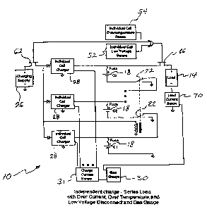
Figure 1 is a schematic of an embodiment of a
device according to the invention;
Figure 2 is a another schematic of the device
depicted in Figure 1;
to Figure 3 is a schematic of another device according
to the invention;
Figure 4 depicts a device according to the
invention inside a human being;
Figure 5 is a schematic of a circuit that may be
used in a device according eo the invention; and
Figure 6 is a flow chart of a method according to
the invention.
Detailed Description
Figures 1-3 depict embodiments of an implantable
energy supply system 1p according to the invention. 'the
supply system 10 may supply energy to a load 14, such as
a ventricular assist pump, hearing assist device, drug
pump, neurostimulator, pacemaker, defibrillator ar total
artificial heart.

CA 02405184 2002-09-25
-3-
The supply system 10 may iruclude at least two cells
18, each of which may be a lithium-ion cell. A switch
22 may be provided, which has a first state in which the
cells 18 are electrically connected to a load 1g. The
S cells 18 may be connected in parallel or in series with
the load 14. The switch 22 may have a second state in
which ~ach cell 18 is electrically connected to its own
cell charger 28. The decision to change the switch 22
between the first and second states may be made by a
machine, such as a microprocessor, or by a human being.
Alternatively, the swi.CCh 22 may be biased to the first
state and moved to the second state when the cell
charger 28 is connected to the cell 18_ The switch 22
may be moved between the first and second states by
connecting or disconnecting, as the case may be, the
cell charger 28 with the corresponding cell 18.
A charge measurer 30 may be electrically connected
to one or more of the cells 18. The charge measurer 30
may provide an indication of the charge on a cell 18 so
that it can be known whether that cell ~.8 is at or below
a low threshold charge level and therefore in need of
charging. The charge measurer 30 may prov~.de an
indication of the charge on a cell 18 so that it can be
known whether that cell 18 is at or above a high
threshold charge level and therefore fully charged.
Flxrther, the charge measurer 30 may provide an
indication of the Charge on a cell Z8 so that it can be
known whether that cell 18 is between the low threshold
and the high threshold charge levels. A charge current
sensor 31 may provide to the charge measurer 30 a signal

CA 02405184 2002-09-25
-4-
indicating the current being delivered to a cell 18.
The charge measurer 30 may include a timer, and when
used in conjunction with the signal provided by the
charge current sensor 31, the amount of energy delivered
to a cell may be determined and used to decide when a
cell 18 is adequately charged. A cell voltage sensor 32
may provide to the charge measurer 30 a signal
indicating the voltage on a cell. The signal provided
by the cell voltage sensor 32 may be used to control the
1.0 charging process that is managed by the cell charger 28_
The charge measurer 30 may provide an indication of
when one or more of the cells 18 may need to be
recharged. The energy supply system 10 may include a
load current monitor 70, which may provide a signal when
the current supplied to the load 14 is below a threshold
level, thereby indicating that one or more of the cells
18 may need to be charged. T'he charge measurer 30 may
be equipped to compare the load current at various times
during discharge of the cells 18, and from this load
current data, predict when a cell or cells 18 should be
recharged. This prediction may be provided in the form
of a signal so that plans may be made to recharge the
cells 18 at a convenient time.
A logic circuit 34 may be electrically connected to
the measurer 30. The logic circuit 34 may include a
microprocessor or an integrated circuit, or both. The
logic circuit 34 may provide signals to disconnect the
load from the cells 18 when the indication of the charge
on an individual cell 18 is below tree low threshold

CA 02405184 2002-09-25
-5-
level, or when an indication of the temperature of an
individual cell 18 is above a threshold level.
The indication of the charge on a cell 18 may be
related to a quantity of energy delivered to the cell
18. For example, the indication. of the charge on a cell
18 may be determined from a voltage differential across
terminals of the cell 18. xhe indication of the charge
on a cell 18 may be dete=mined fxom a rate of current
delivered to the cell 18 and the length of time the
current was delivered.
Energy delivered to the supply system 20 for
charging the cells 18 may be transmitted from a source
38 outside an animal's body 42 t:o a receiver 46 in the
charging power source 26 inside the animal's body 42.
The receiver may be a coil inside the animal's body 42
that is magnetically coupled with a coil in the source
38. A transformer 50 may include both the receivex 46
and devices for converting the energy into electricity
that is usable by the system 10, which may then be
supplied to one or more of the <bells 1B :in order to
charge chose cells 18. The energy supplied by the
source 38 may include radio waves as the primary mode of
transmitting the energy to the receiver 46.
The energy supply system 10 may have a low voltage
sensor 52. The low voltage seneox 52 may b~ capable of
providing a low voltage signal when the voltage on a
cell 18 drops below a threshold level. Further, the
energy supply system 10 may have a temperature monitor

CA 02405184 2002-09-25
-6-
54 joined to one or more of the cells 7.8_ The
temperature monitor 54 may be capable of providing a
high temperature signal, when a temperature of a cell 18
exceeds a threshold temperature. A cell switch 58 (see
Fig. 5) may receive the low voltage signal or the high
temperature signal, and electrically disconnect the
corresponding cell 18. In this manner, a cell 7.8 with a
low voltage, a high tempezature, or both, may be removed
from operation before it causes damage to itself or the
rest of the energy supply system 10.
A charging power source switch 62 may receive the
high temperature signal and electrically disconnect a
charging power source 26. In this manner, the charging
power source 26 may be prevented from providing
electricity in order to avoid causing damage to the
energy supply system l0.
A load switch 66 may receive the low voltage
signal, the high temperatuxe signal, or both, and
elecLrieally disconnect the load 14 from the energy
supply system 10. In this manner, the supply system 10
rnay be removed from operation before it causes damage.
In a method according to th~ invention, a first
cell and a second cell are provided 100. A switch is
provided 104 that has a.first state in which the cells
are electrically connected to a load, and a second state
in which the first cell is electrically connected to its
own charger. A measurer is provided 105, which is
electrically connected to the first cell. The measuxer

CA 02405184 2002-09-25
-?-
is capable of providing an indication of the charge on
the first cell.
When the indication of the charge indicates the
first cell is below a threshold level, the switch may be
S placed 116 in the second state, whereupon electricity is
supplied to the fixst cell. The charge on the first
cell is measured 12o and an indication of the charge is
provided 124. When the indication of the charge
indicates the first cell is above a threshold level, the
1o switch is placed 130 in the first state.
Although the invention has been described with
respect to one or more particular embodiments, it will
be understood that other embodiments of the invention
may be made without departing from the spixit arid scope
15 of the invention.

Dessin représentatif
Une figure unique qui représente un dessin illustrant l'invention.
États administratifs

2024-08-01 : Dans le cadre de la transition vers les Brevets de nouvelle génération (BNG), la base de données sur les brevets canadiens (BDBC) contient désormais un Historique d'événement plus détaillé, qui reproduit le Journal des événements de notre nouvelle solution interne.

Veuillez noter que les événements débutant par « Inactive : » se réfèrent à des événements qui ne sont plus utilisés dans notre nouvelle solution interne.

Pour une meilleure compréhension de l'état de la demande ou brevet qui figure sur cette page, la rubrique Mise en garde , et les descriptions de Brevet , Historique d'événement , Taxes périodiques et Historique des paiements devraient être consultées.

Historique d'événement

Description Date
Demande non rétablie avant l'échéance 2007-09-25
Le délai pour l'annulation est expiré 2007-09-25
Réputée abandonnée - omission de répondre à un avis sur les taxes pour le maintien en état 2006-09-25
Demande publiée (accessible au public) 2003-03-25
Inactive : Page couverture publiée 2003-03-24
Lettre envoyée 2003-03-11
Inactive : CIB attribuée 2003-02-14
Inactive : CIB en 1re position 2003-02-14
Inactive : CIB attribuée 2003-01-21
Inactive : Transfert individuel 2003-01-17
Inactive : Lettre de courtoisie - Preuve 2002-11-12
Demande reçue - nationale ordinaire 2002-11-07
Inactive : Certificat de dépôt - Sans RE (Anglais) 2002-11-07

Historique d'abandonnement

Date d'abandonnement Raison Date de rétablissement
2006-09-25

Taxes périodiques

Le dernier paiement a été reçu le 2005-09-22

Avis : Si le paiement en totalité n'a pas été reçu au plus tard à la date indiquée, une taxe supplémentaire peut être imposée, soit une des taxes suivantes :

  • taxe de rétablissement ;
  • taxe pour paiement en souffrance ; ou
  • taxe additionnelle pour le renversement d'une péremption réputée.

Les taxes sur les brevets sont ajustées au 1er janvier de chaque année. Les montants ci-dessus sont les montants actuels s'ils sont reçus au plus tard le 31 décembre de l'année en cours.
Veuillez vous référer à la page web des taxes sur les brevets de l'OPIC pour voir tous les montants actuels des taxes.

Historique des taxes

Type de taxes Anniversaire Échéance Date payée
Taxe pour le dépôt - générale 2002-09-25
Enregistrement d'un document 2003-01-17
TM (demande, 2e anniv.) - générale 02 2004-09-27 2004-09-09
TM (demande, 3e anniv.) - générale 03 2005-09-26 2005-09-22
Titulaires au dossier

Les titulaires actuels et antérieures au dossier sont affichés en ordre alphabétique.

Titulaires actuels au dossier
WILSON GREATBATCH TECHNOLOGIES, INC.
Titulaires antérieures au dossier
HARRY L., JR. VALENTA
JOSEPH M. PROBST
Les propriétaires antérieurs qui ne figurent pas dans la liste des « Propriétaires au dossier » apparaîtront dans d'autres documents au dossier.
Documents

Pour visionner les fichiers sélectionnés, entrer le code reCAPTCHA :


Pour visualiser une image, cliquer sur un lien dans la colonne description du document. Pour télécharger l'image (les images), cliquer l'une ou plusieurs cases à cocher dans la première colonne et ensuite cliquer sur le bouton "Télécharger sélection en format PDF (archive Zip)" ou le bouton "Télécharger sélection (en un fichier PDF fusionné)".

Liste des documents de brevet publiés et non publiés sur la BDBC .

Si vous avez des difficultés à accéder au contenu, veuillez communiquer avec le Centre de services à la clientèle au 1-866-997-1936, ou envoyer un courriel au Centre de service à la clientèle de l'OPIC.


Description du
Document 
Date
(aaaa-mm-jj) 
Nombre de pages   Taille de l'image (Ko) 
Dessin représentatif 2003-02-17 1 11
Abrégé 2002-09-24 1 11
Description 2002-09-24 7 232
Revendications 2002-09-24 5 108
Dessins 2002-09-24 6 139
Certificat de dépôt (anglais) 2002-11-06 1 161
Courtoisie - Certificat d'enregistrement (document(s) connexe(s)) 2003-03-10 1 130
Rappel de taxe de maintien due 2004-05-25 1 109
Courtoisie - Lettre d'abandon (taxe de maintien en état) 2006-11-19 1 175
Rappel - requête d'examen 2007-05-27 1 118
Correspondance 2002-11-06 1 25
Taxes 2004-09-08 1 35
Taxes 2005-09-21 1 33