Sélection de la langue

Search

Sommaire du brevet 2405933 

Énoncé de désistement de responsabilité concernant l'information provenant de tiers

Une partie des informations de ce site Web a été fournie par des sources externes. Le gouvernement du Canada n'assume aucune responsabilité concernant la précision, l'actualité ou la fiabilité des informations fournies par les sources externes. Les utilisateurs qui désirent employer cette information devraient consulter directement la source des informations. Le contenu fourni par les sources externes n'est pas assujetti aux exigences sur les langues officielles, la protection des renseignements personnels et l'accessibilité.

Disponibilité de l'Abrégé et des Revendications

L'apparition de différences dans le texte et l'image des Revendications et de l'Abrégé dépend du moment auquel le document est publié. Les textes des Revendications et de l'Abrégé sont affichés :

  • lorsque la demande peut être examinée par le public;
  • lorsque le brevet est émis (délivrance).
(12) Demande de brevet: (11) CA 2405933
(54) Titre français: CONTENANT DISTRIBUTEUR A COUVERCLE TOURNANT
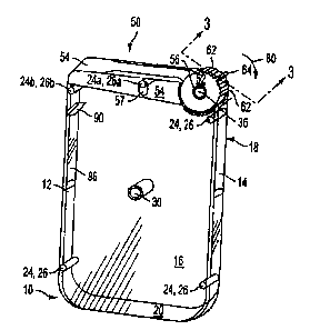
(54) Titre anglais: DISPENSING CONTAINER WITH ROTATABLE LID
Statut: Réputée abandonnée et au-delà du délai pour le rétablissement - en attente de la réponse à l’avis de communication rejetée
Données bibliographiques
(51) Classification internationale des brevets (CIB):
  • B65D 43/16 (2006.01)
  • B65D 47/20 (2006.01)
  • B65D 83/04 (2006.01)
  • B65D 85/60 (2006.01)
  • B65D 85/72 (2006.01)
(72) Inventeurs :
  • BARNES, ROBERT CREGG (Etats-Unis d'Amérique)
  • FISHER, SCOTT LEE (Etats-Unis d'Amérique)
  • SCOTT, DONALD ALLAN (Etats-Unis d'Amérique)
  • JOCHEM, DAVID JOHN (Etats-Unis d'Amérique)
  • MANDLE, JAMES S. (Etats-Unis d'Amérique)
(73) Titulaires :
  • WM. WRIGLEY JR. COMPANY
(71) Demandeurs :
  • WM. WRIGLEY JR. COMPANY (Etats-Unis d'Amérique)
(74) Agent: OSLER, HOSKIN & HARCOURT LLP
(74) Co-agent:
(45) Délivré:
(22) Date de dépôt: 2002-09-30
(41) Mise à la disponibilité du public: 2003-04-01
Requête d'examen: 2007-08-24
Licence disponible: S.O.
Cédé au domaine public: S.O.
(25) Langue des documents déposés: Anglais

Traité de coopération en matière de brevets (PCT): Non

(30) Données de priorité de la demande:
Numéro de la demande Pays / territoire Date
09/966,760 (Etats-Unis d'Amérique) 2001-10-01

Abrégés

Abrégé anglais


A dispensing container is formed having a housing with an opening at the top
and defining an internal cavity. A wheel is rotatably attached to the housing
and
includes an arm which extends from the wheel and is dimensioned to cover the
opening. The wheel with the extending arm is adapted to pivot away from the
opening
when the wheel is rotated, thereby allowing one to dispense the contents
present in the
container.

Revendications

Note : Les revendications sont présentées dans la langue officielle dans laquelle elles ont été soumises.


What is claimed is:
1. A dispensing container comprising:
a housing defining an internal cavity and including an aperture;
a wheel rotatably attached to said housing for rotation about a fixed axis and
having a radially extending arm, said arm dimensioned to cover said aperture
and to
pivot away from said aperture when said wheel is rotated about said axis,
thereby
uncovering said aperture.
2. The container of claim 1, wherein said wheel is biased to urge said arm to
a
position to cover said aperture.
3. The container of claim 2, wherein said wheel is biased via a tab axially
extending
from said wheel cooperatively engaging with a tooth portion of said housing.
4. The container of claim 3, wherein said tab is composed of a resilient
material
adapted to pivotally twist about said tooth portion when said wheel is
rotated, thereby
establishing a biasing force.
5. The container of claim 1, wherein said wheel comprises a plurality of
radially
extending ridges.
7

6. The container of claim 5, wherein said ridges provide a gripable surface
upon
which a rotation force can be applied.
7. The container of claim 5, wherein one of said ridges extends radially
further than
the remainder of plurality of radially extending ridges, said one ridge
providing an
actuatable surface upon which a rotation force can be applied.
8. The container of claim 1, wherein said wheel comprises a radially extending
ridge
providing an actuatable surface upon which a rotation force can be applied.
9. The container of claim 1, further comprising a deflection plate extending
from an
inner surface of said housing adjacent said aperture, said deflector plate
angled towards
said aperture and adapted to direct contents within said container toward said
aperture
during dispensing.
10. A dispensing container comprising:
a housing having two pairs of opposing sides, a bottom, and an upper opening
opposite said bottom, said housing defining an internal cavity;
a wheel rotatably attached to said housing adjacent said opening and extending
through one of said sides, said wheel having a radially extending arm, said
wheel and
said arm dimensioned to cover said opening, said arm adapted to pivot away
from said
opening when said wheel is rotated about its axis, thereby providing for
dispensing of
contents from said internal cavity.
8

11. The container of claim 10, wherein said wheel is biased to maintain said
arm in a
position covering said opening.
12. The container of claim 10, wherein said wheel is biased via a tab axially
extending from said wheel cooperatively engaging with a tooth portion of said
housing.
13. The container of claim 12, wherein said tab is composed of a resilient
material
adapted to pivotally twist about said tooth portion when said wheel is
rotated, thereby
establishing a biasing force.
14. The container of claim 10, wherein said wheel comprises a plurality of
radially
extending ridges.
15. The container of claim 14, wherein said ridges provide a gripable surface
upon
which a rotation force can be applied.
16. The container of claim 14, wherein one of said ridges which extends
radially
further than the remainder of radially extending ridges, said one ridge
providing an
actuatable surface upon which a rotational force can be applied.
17. The container of claim 10, wherein said wheel comprises a radially
extending
ridge providing an actuatable surface upon which a rotation force can be
applied.
9

18. The container of claim 10, further comprising a deflector plate extending
from an
inner surface on said side opposite said side through which said wheel
extends, said
deflector plate angled towards said opening and adapted to direct contents
within said
container toward said opening during dispensing.
10

Description

Note : Les descriptions sont présentées dans la langue officielle dans laquelle elles ont été soumises.

CA 02405933 2002-09-30
DISPENSING CONTAINER WITH ROTATABLE LID
FIELD OF THE INVENTION
[0001] The present invention relates to a container, and in particular, to a
dispensing container with a rotatable lid for dispensing food products.
BACKGROUND OF THE INVENTION
[0002] Containers for packaging and dispensing food products such as candy
come in a wide variety of sizes and shapes. These containers rnay be handheld
and
adapted to fit in a purse or in a pocket of a shirt or pair of pants. Further,
these
containers help to prevent damage to the food product contained within and to
maintain
its freshness. There exists a need for new and improved containers far
dispensing food
products such as candy.
BRIEF SUMMARY OF THE INVENTION
[0003] In accordance with a general object of the present invention, a
dispensing
container is provided for storing and dispensing food products such as candy
wherein
the dispensing container has an easy opening lid for dispensing a food
product.
[0004] It is an additional object of the present invention to provide a
dispensing
container dimensioned to fit comfortably in the palm of a hand.

CA 02405933 2002-09-30
[0005] According to one aspect of the present invention, a dispensing
container
includes a housing defining an internal cavity and including an aperture. A
wheel is
rotatably attached to the housing and has an extending arm which is
dimensioned to
cover the aperture and to pivot away from the aperture when the wheel is
rotated,
thereby uncovering the aperture. In one advantageous further embodiment, the
wheel
is biased to cause the arm to cover the aperture.
[0006] In accordance with another aspect of the present invention, a
dispensing
container includes a housing having two pairs of opposing sides, a bottom, and
an
opening opposite the bottom. The housing defines an internal cavity. A wheel
is
rotatably attached to the housing adjacent the opening and the wheel extends
through
one of the sides. The wheel has an extending arm and the wheel and arm are
dimensioned to cover the opening. The arm is adapted to pivot away from the
opening
when the wheel is rotated for dispensing contents of the container. In one
advantageous further embodiment, the wheel is biased to maintain the arm in a
position
to cover the opening.
(0007] A feature of the present invention relates to the dispensing of food
product
from the container by rotating the wheel and using a slight pouring action to
dispense
food product from the container.
(0008] An additional feature of the present' invention, in one form thereof,
concerns the incorporation of a biased wheel to support the arm so that it
covers the
opening of the container, thereby preventing food product from inadvertently
being
dispensed and helping to maintain the freshness of the food product within the
container.
2

CA 02405933 2002-09-30
[0009] Further features and advantages of the present invention will be set
forth in,
or apparent from, the detailed description of preferred embodiments thereof
which follows.
BRIEF DESCRIPTION OF THE DRAWINGS
[0010] The invention will now be described in detail with respect to preferred
embodiments with reference to the accompanying drawings, wherein:
[0011] Figure 1 is a perspective view of a dispensing container according to
the
present invention in a closed condition;
[0012] Figure 2 is a partial perspective view of the container of Figure 1 in
an
opened condition;
[0013] Figure 3 is an elevational view, partially in section taken along line
3-3 of
Figure 1;
[0014] Figure 4 is an elevational view, partially in section taken along fine
4-4 of
Figure 2;
[0015] Figure 5A is a perspective view of the main body of the dispensing
container according to the present invention, shown in a disassembled
condition; and
[0016] Figure 5B is a perspective view of the lid according to the present
invention.
DETAILED DESCRIPTION OF THE INVENTION
[0017] Referring now to the drawings, like numbers represent like elements
throughout the several views. Reference numeral 10 generally identifies a
dispensing
3

CA 02405933 2002-09-30
container shown in a closed condition in Figures 1 and 3 and in an opened
condition in
Figures 2 and 4. The container 10 includes a housing having a first pair of
opposing
sides 12, 14 and a second pair of opposing sides 16, 18. The housing also
includes a
bottom 20 and an upper opening 22 opposite the bottom 20. Extending between
sides
16 and 18 are mating connectors including three mating connectors 24 and 26,
one set
of connectors 24a and 26a and one set 24b and 26b. Support post 30 provides
rigidity
to sides 16 and 18. As shown, all sides of container 10 are made of
transparent or
translucent material. Of course such sides can also be made of opaque
material.
[0018) Lid 50, which is dimensioned to cover opening 22, comprising a wheel
portion 52 and an extending arm 54. Wheel 52 includes bore 56 and a plurality
of
ridges 62 which extend upwardly from the surface of wheel 52. One ridge 64
extends
further from the surface of wheel 52 than the remaining plurality of ridges
62. The bore
56 is mounted on an axle 36 which is fixed to wall 18, as shown in Figure 5A.
[0019] Lid 50 is retracted away from opening 22 by applying a rotational force
to
wheel 52 in the direction denoted by arrow 80. This rotational force rotates
wheel 52
and in particular, bore 56 about fixed axle 36, allowing arm 54 to pivot away
from
opening 22 (Figure 2). Advantageously, the plurality of ridges 62 provide a
gripable
surface and ridge 64 provides an additional surface to which one can apply the
rotational force. Connectors 24a, 26a pass through aperture 57 in the arm 54
to provide
guide and a stop to limit the angle through which wheel 52 can rotate.
[0020] Lid 50 is biased to be maintained in a closed condition covering
opening
22. The biasing of lid 50 is due to a cooperative engagement between teeth 38,
40,
which are fixed to and extending from the surtace of side 18, and tabs 58, 60,
extending
4

CA 02405933 2002-09-30
axially from wheel 52 (Figures 3-5). In this engagement, a portion of tab
surfaces 59,
61 of tabs 58, 60 abut a portion of angled surfaces 42, 44 of teeth 38, 40
respectively.
When a rotational force causes wheel 52 to rotate in direction of arrow 80
(Figure 1 ), tab
surfaces 59, 61 of tabs 58, 60 pivotally twist along angled surfaces 42, 44,
of teeth 38,
40, respectively, resulting in the deformation of tabs 58, 60 shown in Figure
4.
[0021] Advantageously, tabs 58, 60 are constructed of a resilient material
such
as polypropylene, which provides a resilient, biasing force to return tabs 58,
60 to their
rest position once the rotational force is withdrawn from wheel 52. As a
result, the
biasing force closes lid 50 so that it covers opening 22 after the rotational
force is
withdrawn.
j0022] Preferably, lid 50 can be rotated by holding container 10 in the palm
of
one hand while applying a rotational force to ridges 62 and ridge 64 using the
thumb of
that hand. Food product such as candy is then dispensed into the other hand by
slightly
inverting or pouring the food product present in the container 10 into the
other hand.
[0023) Spanning the space between side 16 and side 18 is a deflector plate 90
formed from deflector plate portions 92, 94 extending from sides 16, 18
respectively.
Deflector plate 90 is angled towards opening 22 and, preferably, extends at
least as far
from the interior wall surtace 96 of side 12 as that of connector 24b (best
shown in
Figures 3 and 4).
[0024) Deflector plate 90 acts to deflect food product away from connector 24b
and towards opening 22 when the food product is dispensed. For example, during
dispensing, after arm 54 is retracted from opening 22 and container 10 is
tilted to permit

CA 02405933 2002-09-30
dispensing of the food product of container 10, the food product will be
deflected away
from connector 24b by deflector plate 90, and directed toward opening 22.
[0025] Referring now specifically to Figures 5A and 5B, container 10 is
assembled by first inserting bore 56 of lid 50 onto axle 36 so that tab
surfaces 59, 61 of
tabs 58, 60 abut angled surfaces 42, 44 of teeth 38, 40. Then, side 16 is
folded along
hinge 28 to align and mate connectors 24, 24a and 24b with complementary
plurality of
connectors 26, 26a and 26b.
[0026] It will be apparent to one of ordinary skill in the art that container
10
provides numerous features and advantages. For example, the plurality of
ridges and in
particular the further extending ridge 64 enables one to readily rotate the
wheel 52
which then pivots arm 54 away from opening 22 for easy dispensing of food
product
from container 10. Further, a preferable size of container 10 provides for a
dispensing
container which can fit in the palm of a hand for easy dispensing of food
product and
which can readily be stowed in a purse or in a shirt, pants, or backpack
pocket.
[0027] Althaugh the invention has been described in detail with respect to the
preferred embodiments thereof, it will be apparent to one of ordinary skilled
in the art
that the invention is capable of numerous modifications and variations within
the scope
and spirit of the invention.
6

Dessin représentatif
Une figure unique qui représente un dessin illustrant l'invention.
États administratifs

2024-08-01 : Dans le cadre de la transition vers les Brevets de nouvelle génération (BNG), la base de données sur les brevets canadiens (BDBC) contient désormais un Historique d'événement plus détaillé, qui reproduit le Journal des événements de notre nouvelle solution interne.

Veuillez noter que les événements débutant par « Inactive : » se réfèrent à des événements qui ne sont plus utilisés dans notre nouvelle solution interne.

Pour une meilleure compréhension de l'état de la demande ou brevet qui figure sur cette page, la rubrique Mise en garde , et les descriptions de Brevet , Historique d'événement , Taxes périodiques et Historique des paiements devraient être consultées.

Historique d'événement

Description Date
Inactive : Regroupement d'agents 2013-10-24
Demande non rétablie avant l'échéance 2011-02-04
Inactive : Morte - Aucune rép. dem. par.30(2) Règles 2011-02-04
Réputée abandonnée - omission de répondre à un avis sur les taxes pour le maintien en état 2010-09-30
Inactive : Abandon. - Aucune rép dem par.30(2) Règles 2010-02-04
Inactive : Dem. de l'examinateur par.30(2) Règles 2009-08-04
Lettre envoyée 2007-09-18
Requête d'examen reçue 2007-08-24
Exigences pour une requête d'examen - jugée conforme 2007-08-24
Toutes les exigences pour l'examen - jugée conforme 2007-08-24
Inactive : CIB de MCD 2006-03-12
Lettre envoyée 2006-01-16
Inactive : Transferts multiples 2005-12-16
Demande publiée (accessible au public) 2003-04-01
Inactive : Page couverture publiée 2003-03-31
Inactive : CIB en 1re position 2003-01-09
Inactive : CIB attribuée 2003-01-09
Inactive : Certificat de dépôt - Sans RE (Anglais) 2002-11-15
Exigences de dépôt - jugé conforme 2002-11-15
Lettre envoyée 2002-11-15
Demande reçue - nationale ordinaire 2002-11-13

Historique d'abandonnement

Date d'abandonnement Raison Date de rétablissement
2010-09-30

Taxes périodiques

Le dernier paiement a été reçu le 2009-09-17

Avis : Si le paiement en totalité n'a pas été reçu au plus tard à la date indiquée, une taxe supplémentaire peut être imposée, soit une des taxes suivantes :

  • taxe de rétablissement ;
  • taxe pour paiement en souffrance ; ou
  • taxe additionnelle pour le renversement d'une péremption réputée.

Veuillez vous référer à la page web des taxes sur les brevets de l'OPIC pour voir tous les montants actuels des taxes.

Historique des taxes

Type de taxes Anniversaire Échéance Date payée
Enregistrement d'un document 2002-09-30
Taxe pour le dépôt - générale 2002-09-30
TM (demande, 2e anniv.) - générale 02 2004-09-30 2004-09-14
TM (demande, 3e anniv.) - générale 03 2005-09-30 2005-09-08
Enregistrement d'un document 2005-12-16
TM (demande, 4e anniv.) - générale 04 2006-10-02 2006-09-14
Requête d'examen - générale 2007-08-24
TM (demande, 5e anniv.) - générale 05 2007-10-01 2007-09-10
TM (demande, 6e anniv.) - générale 06 2008-09-30 2008-09-17
TM (demande, 7e anniv.) - générale 07 2009-09-30 2009-09-17
Titulaires au dossier

Les titulaires actuels et antérieures au dossier sont affichés en ordre alphabétique.

Titulaires actuels au dossier
WM. WRIGLEY JR. COMPANY
Titulaires antérieures au dossier
DAVID JOHN JOCHEM
DONALD ALLAN SCOTT
JAMES S. MANDLE
ROBERT CREGG BARNES
SCOTT LEE FISHER
Les propriétaires antérieurs qui ne figurent pas dans la liste des « Propriétaires au dossier » apparaîtront dans d'autres documents au dossier.
Documents

Pour visionner les fichiers sélectionnés, entrer le code reCAPTCHA :


Pour visualiser une image, cliquer sur un lien dans la colonne description du document. Pour télécharger l'image (les images), cliquer l'une ou plusieurs cases à cocher dans la première colonne et ensuite cliquer sur le bouton "Télécharger sélection en format PDF (archive Zip)" ou le bouton "Télécharger sélection (en un fichier PDF fusionné)".

Liste des documents de brevet publiés et non publiés sur la BDBC .

Si vous avez des difficultés à accéder au contenu, veuillez communiquer avec le Centre de services à la clientèle au 1-866-997-1936, ou envoyer un courriel au Centre de service à la clientèle de l'OPIC.


Description du
Document 
Date
(aaaa-mm-jj) 
Nombre de pages   Taille de l'image (Ko) 
Dessin représentatif 2003-01-13 1 9
Page couverture 2003-03-07 1 36
Abrégé 2002-09-30 1 13
Description 2002-09-30 6 229
Revendications 2002-09-30 4 98
Dessins 2002-09-30 5 67
Courtoisie - Certificat d'enregistrement (document(s) connexe(s)) 2002-11-15 1 109
Certificat de dépôt (anglais) 2002-11-15 1 161
Rappel de taxe de maintien due 2004-06-01 1 109
Rappel - requête d'examen 2007-07-04 1 118
Accusé de réception de la requête d'examen 2007-09-18 1 189
Courtoisie - Lettre d'abandon (R30(2)) 2010-04-29 1 164
Courtoisie - Lettre d'abandon (taxe de maintien en état) 2010-11-25 1 172
Taxes 2004-09-14 3 85
Taxes 2005-09-09 1 47
Taxes 2006-09-14 1 49
Taxes 2007-09-10 1 50
Taxes 2008-09-17 1 55
Taxes 2009-09-17 1 53