Note : Les descriptions sont présentées dans la langue officielle dans laquelle elles ont été soumises.
CA 02406313 2002-10-11
WO 01/80393 PCT/SE01/00826
METHOD AND DEVICE FOR POWER SYSTEM PROTECTION
TECHNICAL FIELD
The present invention relates to a method for protecting a zone in a
power system, which zone comprises a number of transmission lines
connected to power sources and a number of transmission lines
connected to a number of loads where the power sources and the loads
are arranged outside the zone, wherein the method comprises the steps
of: continuously measuring all the incoming currents (Ii") to the zone,
continuously measuring all the outgoing currents (Iout) from the zone,
and continuously calculating the differential current (Id) according to
Id = lin - Lout.
BACKGROUND OF THE INVENTION
During a number of years there has been a rapid development of power
systems and the capacity requirements of these in turn require highly
reliable relaying principles for protecting the system or components of
the system in case of faults. These protection requirements apply to
many parts of the power system such as for example transformer
differential protection, motor differential protection, generator
differential protection and busbar protection.
In this kind of protection system, the incoming and outgoing currents of
a certain protection zone has been measured since these may be used
to detect if a fault occurs within or outside the protection zone. In order
to measure these currents, so called current transformers, or CT, are
used, one on each incoming and outgoing line. Further each line is
provided with a circuit breaker for breaking the line in case of a fault.
Traditionally the secondary currents of all the CTs are lead to a central
differential relay which calculates the differential and the restraint
current, compares them and makes the decision whether to trip all
breakers of the in- and outgoing lines of the protection zone. In the case
CA 02406313 2002-10-11
WO 01/80393 PCT/SE01/00826
2
of an internal fault, i e a fault within the protection zone, the differential
relay should trip the breakers.
If however the differential relay trips all circuit breakers during an
external fault, or misoperates in normal operating conditions, this will
cause serious technical and economical consequences for the power
system.
One solution to this is to have a distributed, or decentralised, algorithm
processing principle. This principle is presented in the paper
"Implementation of a distributed digital bus protection system", by He
Jaili et al., IEEE Transaction on Power Delivery, Vol. 12, No. 4, October
1997. Here the whole bus protection system is divided into a number of
protection units, each installed on one circuit of the bus, i e incoming
and outgoing transmission line or transformer. All the protection units
are connected by a data communication network. Each unit samples
and compares instantaneous values of the differential and restraint
currents, and makes a decision whether or not to trip its own circuit
breaker.
The low impedance protection algorithm widely used in digital
protection systems may be expressed as follows. If for example we
suppose a busbar which connects N lines, the differential current Id and
restraint current Ir among these lines are expressed as
N
Id = YI- (1)
H
N
Ir = LII (2)
i=1
Id klr > D (3)
CA 02406313 2002-10-11
WO 01/80393 PCT/SE01/00826
3
In case of an internal fault, then Id = Ir and equation (3) can be
confirmed if proper values to k (k< 1) and D are chosen. Equation (3) is
also known as the percentage differential protection since it introduces
the restraint current in order to make the protection more stable for
external faults.
In the case of normal loads or external faults, Id should be zero in order
for equation (3) to be satisfied and no trip signal will be issued.
However, for external faults, Id will be greater than zero during the
saturation period of the CT, causing a misoperation during this time
period. Saturation occurs as a result of unpredictably high fault
currents, during which, the CT saturates and produces erroneous non-
proportional values for the actual current. The main technical problem
for the differential protection algorithm is thus misoperation due to
external faults principally because the saturation of the CT in the
faulted line will produce a picture similar to an internal fault in the
measuring circuits, that is to say, the differential current Id will be the
same as the restraint current Ir during the saturation period of the CT
when an external fault occurs.
Another problem with the above system is that it, due to the above
mentioned transformer saturation problems, requires a stabilised
restraint current signal to keep stability in the case of an external fault.
As a consequence the tripping time is increased to above 20
milliseconds. For many systems it is however required to have faster
tripping signals, preferably below 15 milliseconds due to system
stability and safety requirements.
CA 02406313 2010-02-10
4
BRIEF DESCRIPTION OF THE INVENTION
One object of the present invention is to provide a fast tripping
algorithm for power system protection that remedies the above
mentioned problems encountered with present technology.
An additional object of the present invention is to provide a means to
guaranty supply of electric power through a protected zone in a case
when a fault is external to the protected zone.
According to the present invention, there is provided a method for protecting
a zone
in a power system, which zone comprises a number of transmission lines
connected
to power sources and a number of transmission lines connected to a number of
loads
where the power sources and the loads are arranged outside the zone, wherein
the
method comprises the steps of:
- continuously measuring all the incoming currents lin to the zone,
- continuously measuring all the outgoing currents lout from the zone, and
- continuously calculating the differential current Id according to:
ld = lin - lout,
characterised in continuously integrating lin, lout and Id according to:
(t l+T )
Ix = f Ldt
it
where T is the fundamental frequency cycle, to obtain integrated values ID,
IIN,
TOUT:
continuously differentiating the values of IIN1TOUT and ID according to:
k1 (t) = d(ID(t))/dt
k2(t) = d(lIN(t))/dt
k3(t) = d(IOUT(t)/dt,
CA 02406313 2010-02-10
4a
where k1, k2 and k3 constitute rate of change values, and
if using a discrete time domain system, the rate of change values are
expressed as:
k1(i) = lD(i) - Ip(i-1)
k2(i) = IIN(i) - IIN(i-1)
k3(i) = IOUT(i) - IOUT(i-1)
and
- continuously comparing the rate of change values k1(i), k2(i) and k3(i) with
set
threshold values in a logic, and when the logic is fulfilled, producing a
tripping signal.
According to the present invention, there is also provided a device for
protecting a
zone in a power system, which zone (PZ) comprises a number of transmission
lines
(12) connected to power sources and a number of transmission lines connected
to a
number of loads where the power sources and the loads are arranged outside the
zone, comprising means (CT) for continuously measuring all the incoming
currents to
the zone, means (CT) for continuously measuring all the outgoing currents from
the
zone, and means (14) for continuously calculating the differential current
according
to:
Id = Iin - lout,
characterised in means for continuously integrating lin, lout and Id according
to..
(t 1+T)
Ix = Jlxdt
11
where T is the fundamental frequency cycle, to obtain integrated values 'ins
lout, Id
means for continuously differentiating the values of Iin, lout and Id
according to:
k1 (t) = d(ID(t))/dt
k2(t) = d(IIN(t))/dt
CA 02406313 2010-02-10
4b
k3(t) = d(IOUT(t))/dt,
where k1, k2 and k3 constitute rate of change values, and
if using a discrete time domain system, the rate of change values are
expressed as..
k1(i) = lD(i) - ID(i-1)
k2(i) = IIN(i) - IIN(i-1)
k3(i) = IOUT(i) - IOUT(i-1)
and
means for continuously comparing the rate of change values k1(i), k2(i) and
k3(i) with
set threshold values in a logic, and when the logic is fulfilled, producing a
tripping
signal.
According to the present invention, there is also provided a method to
guaranty
supply of electric power through a first zone in a power network, which said
power
network includes other zones in any one or of which a fault may, which
guaranty is
provided by means of a protection scheme for said first area comprising a
method
implemented by a computer program wherein the protection scheme includes the
steps of:
- measuring current passing into and out of the first protected zone
- applying a logical test to determine if a detected fault is an internal
fault or not,
wherein the protection scheme method includes at least one further step of
continuously integrating measured values for incoming current and outgoing
current, to:
- continuously calculating the differential current Id according to:
Id = Iin - lout,
- continuously integrating Iin, lout and Id according to:
(tl+T)
Ix ^ f Ixdt
tl
where T is the fundamental frequency cycle,
- continuously differentiated according to:
CA 02406313 2010-02-10
4c
k1 (t) = d(ID(t))/dt
k2(t) = d(IIN(t))/dt
k3(t) = d(IOUT(t))/dt,
where k1, k2 and k3 constitute rate of change values, and
using a discrete time domain system, wherein the rate of change values are
expressed as:
k1(i) = ID(i) - Ip(i-1)
k2(i) = IIN(i) - IIN(i-1)
k3(i) = IOUT(i) - IOUT(i-1)
and
continuously comparing the rate of change values k1(i), k2(i) and k3(i) with
set
threshold values in a logic, and when the logic is fulfilled, producing a
tripping signal.
The present invention displays a number of advantages over the state of
the art. Since the integrated values of the incoming, outgoing and
differential currents are used for determining where a fault has
occurred, much more stable values are obtained. This means that the
evaluation will be more reliable and accurate and that external faults
will not wrongly trip the protection device. Because the rate of change
values, based on the incoming, outgoing and differential currents,
display very characteristic behaviour depending on whether the fault is
inside or outside the protection zone, the risk of wrongly tripping the
system is substantially reduced.
Further the protection device will not be influenced by current
transformer saturation with the present invention. With the algorithm
presented, a very fast tripping signal may be obtained that operates
either well below the fault current levels or well below the operational
time of conventional protection devices.
Another advantage of an embodiment of the present invention is that
the method may be used to guaranty power transmission through a
CA 02406313 2002-10-11
WO 01/80393 PCT/SE01/00826
protected area in the case of a fault that is external to the protected
area. Such a guaranty of assured supply with greatly reduced risk of
power outages, brownouts etc due to faulty tripping in a protected area
is of great economic benefit, especially to a supplier of electrical power.
5 Such a guaranty facilitates the avoidance of unnecessary loss of supply
leading to extremely expensive consequences in terms of lost
production, scrapped production, downtime of expensive plant and so
on.
These and other aspects of, and advantages with, the present invention
will become apparent from the detailed description and from the
accompanying drawings.
BRIEF DESCRIPTION OF THE DRAWINGS
In the detailed description of the invention, reference will be made to the
accompanying drawings, of which
Fig. 1 shows schematically the principle of a protection zone
according to the invention,
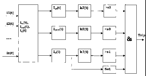
Fig. 2 shows a flow chart for a fast tripping logic,
Fig. 3 shows an example of a test result for an internal fault when
using the method according to the invention,
Fig. 4 shows an example of a test result for an external fault when
using the method according to the invention, and
Fig. 5 shows schematically a device for performing the method
according to the invention.
CA 02406313 2002-10-11
WO 01/80393 PCT/SE01/00826
6
DETAILED DESCRIPTION OF THE INVENTION
The present invention relates to protection of power systems, and in
particular to areas of power systems having no sources or loads within
those areas. These areas will hereafter be named protection zones PZ.
Within these zones a number of feed lines connected to external sources
are arranged as well as a number of feed lines connected to external
loads. External in this context means outside the protection zone. The
protection zone does not contain any sources or loads and can be seen
as a passive part of a power system.
In Fig. 1 is shown schematically the principle of the protection zone PZ.
The total current from all sources entering the zone is referred to as ,;n
and the total current to all loads from PZ is referred to as Iout. The
currents are conventionally measured by current transformers CT. For
a given PZ it is quite clear that all incoming currents have to be equal to
the outgoing currents in normal load cases, when the PZ is defined as
above, i e Iin = Iout or Iout/,in = 1. This is also true if an external fault
occurs.
If one phase is considered in a PZ and we suppose that N feed lines are
present in a certain PZ, the incoming current Iin and outgoing current
Iout of the phase can be obtained by equations (1) and (2):
M
Iin = Ii (1)
i=1
N
,out = YIi (2)
i=M+1
CA 02406313 2002-10-11
WO 01/80393 PCT/SE01/00826
7
Here, the index i from 1 to M corresponds to the incoming currents to
PZ and i from M+ 1 to N corresponds to the outgoing currents from the
protection zone.
The instantaneous values of the differential current Id and the
restrained current Ir can be expressed by Iin and Iout as
Id=lin - Iout (3)
Ir = Iin + Iout (4)
In order to have stable values of the incoming current Iin and the
outgoing current Im for a certain protection zone, integrated values of
these currents as well as Id can be obtained by integration over each
fundamental frequency cycle T as
(tl+T)
hN = f L dt (5)
t1
(t1+T)
IOUT = f 1-& (6)
t1
(tl+T)
ID = f I,dt (7)
ti
The integrated values obtained from equations (5)-(7) will be used to
form an algorithm by which faults inside the protection zone are
detected very fast and by means of which a very fast tripping signal may
be generated, disconnecting the zone from the power system.
For most power systems, in case of serious faults, tripping must be
done very quickly because of the stability of the system but also in
CA 02406313 2002-10-11
WO 01/80393 PCT/SE01/00826
8
order to prevent serious damages. Preferably a tripping signal should be
produced within 5 ms following internal faults.
This may be achieved with the present invention by using the rate of
change of the integrated continuous values of IIN, IOUT and ID. The fact
that all of these three integration values are one variable function in the
time domain if a continuous integration is performed is used. This
means that integration values will change depending on when the
integration is performed. If we suppose that
ki(t) = d(ID(t)) / dt
k2(t) = d(IIN(t)) / dt
k3(t) = d(IOUT(t)) / dt (8)
where ki, k2, k3 are rate of change values. If a discrete time domain
system is used, the rate of change values may be expressed as
ki(i) = ID(i) - ID(i-1)
k2(i) = IIN(i) - IIN(i-1)
k3(i) = IOUT(i) - IOUT(i-1)
Here, index i corresponds to the sampling instant in the discrete time
domain and i-1 corresponds to the previous sampling time.
It has been shown that there exists differences for the factors ki(i), k2(i)
and k3(i) for different cases such as normal load, external faults and
internal faults. This is shown in table 1 below.
Normal load cases External fault cases Internal fault cases
ki(i) = 0 ki(i) increases after ki(i) increases
CA 02406313 2002-10-11
WO 01/80393 PCT/SE01/00826
9
saturation of current
transformer
k2(i) = 0 k2(i) increases k2(i) increases
k3(i) = 0 k3(i) increases before k3(i) decreases
saturation of current
transformer
By continuously monitoring the rate of change values ki, k2 and k3 a
logic may be created for producing a fast tripping signal.
The logic for tripping when an internal fault occurs may by built up as
is shown in Fig. 2.
The factors ki, k2 and k3 are each checked against set threshold values,
Si, s2, and s3 respectively, in three separate comparators. As seen from
table 1 above the logic is designed to work as follows. Since kl(i)
increases during an internal fault, it is checked if it reaches above the
set value si, since k2(i) also increases during an internal fault, it is
checked if it reaches above the set value s2 and since k3(i) decreases
during an internal fault, it is checked if it reaches below the set value
s3. The comparators are connected to an AND function and if the AND
function reaches signals from all the comparators a signal is
transmitted to a second AND function.
The integrated value ID(i) is also checked against a set threshold value
in a separate comparator. In this case for internal faults ID(i) should be
above a set pickup value. If so, a signal will sent to the second AND
function and together with the signal from the first AND function a
tripping signal will be issued.
During tests of the fast tripping algorithm and logic of the present
invention it has been found that the threshold values si, s2 and s3
CA 02406313 2002-10-11
WO 01/80393 PCT/SE01/00826
should be in the range 5-50% of the integrated value of the incoming
current, and preferably 5-25%.
Figure 3 shows as an example a diagram over a test of the present
5 invention for an internal fault. As can be seen from the diagram the rate
of change values ki(i), k2(i) and k3(i) all have distinct peaks just at the
occurrence of an internal fault, where ki(i) and k2(i) increase while k3(i)
decreases.
10 Figure 4 shows another test example for an external fault. In this case
k2(i) and k3(i) increase rapidly just at the occurrence of an external
fault, while ki(i) remains unchanged until the CT saturates and ki(i)
increases rapidly.
As can be seen from the examples, there are very distinct differences
between internal and external faults. Further, with the method
according to the invention a very fast tripping signal may be obtained.
Figure 5 schematically shows how the method according to the
invention may be implemented in a power system. A busbar 10 is
connected to a number of transmission lines 12, where some are
incoming lines connected to power sources and some are outgoing lines
connected to loads. The connection of the transmission lines to the
busbar is considered to be the protection zone PZ.
Each transmission line is arranged with a current transformer CT. Each
transmission line is further provided with a breaker 13, capable of
breaking the connection. The CTs are connected to a fast tripping device
14 via lines 16. The CTs are designed to provide currents that are
proportional to the currents of the transmission lines. The fast tripping
device comprises means for carrying out the steps of measuring the
currents, calculating the differential current, integrating the currents,
CA 02406313 2002-10-11
WO 01/80393 PCT/SE01/00826
11
differentiating the integrated values in order to obtain the rate of change
values, comparing the rate of change values with threshold values and
producing a tripping signal. The tripping signal is transmitted to all
breakers arranged on the transmission lines via line 18.
The fast tripping device may comprise filters for filtering the signals,
converters for sampling the signals and one or more micro computers.
The micro processor (or processors) comprises a central processing unit
CPU performing the steps of the method according to the invention.
This is performed with the aid of a dedicated computer program, which
is stored in the program memory. It is to be understood that the
computer program may also be run on a general purpose industrial
computer instead of a specially adapted computer.
The software includes computer program code elements or software
code portions that make the computer perform the method using
equations, algorithms, data and calculations previously described. A
part of the program may be stored in a processor as above, but also in a
ROM, RAM, PROM or EPROM chip or similar. The program in part or in
whole may also be stored on, or in, other suitable computer readable
medium such as a magnetic disk, CD-ROM or DVD disk, hard disk,
magneto-optical memory storage means, in volatile memory, in flash
memory, as firmware, or stored on a data server.
A further embodiment of the present invention constitutes a method to
guaranty supply of electric power through a protected zone by
means of determining if a detected fault is external to the zone or not.
The fast tripping method and algorithm according to the
invention is used to determine if a fault is external or not, and so
guaranty that a protection device in the protected zone will
not trip in response to an external fault.
CA 02406313 2002-10-11
WO 01/80393 PCT/SE01/00826
12
The method comprises supplying a power network with a fast tripping
device as described above functioning according to the method and logic
as described above. The method to assure supply is a method to reduce
the risk of power outages due to faulty tripping in a protected zone,
leading to loss of supply. Loss of supply can have extremely expensive
consequences in terms of lost production, scrapped production,
downtime of expensive plant and so on.
It is to be understood that the embodiments described above and shown
on the drawings are to be regarded as non-limiting examples of the
present invention and that it is defined by the appended patent claims.