Note : Les descriptions sont présentées dans la langue officielle dans laquelle elles ont été soumises.
CA 02406320 2002-10-02
HEIGHT ADJUSTABLE DESK
FIELD OF THE INVENTION
This invention relates to a height adjustable desk and more particularly to a
height adjustable desk which utilizes an upwardly biased force to provide lift
to the
desk.
BACKGROUND OF THE INVENTION
It is known to provide desks or work stations which allow the user to adjust
the
height thereof. This height adjustment allows for differences in the heights
of the
users or to adjust the height of the work surface depending on the task at
hand.
Known height adjustment of desks and work stations is achieved in various
manners.
Often, to adjust the height of the desk, significant time and effort is
involved. For
example, rudimentary systems involve manually adjusting the length of each of
the
legs of the desk. Other height adjustment systems have the desk attached to a
base
support via a telescoping support member or members which may be secured at
various vertical positions. Such systems require the user to manually expand
or retract
the telescoping support member and then fix it in place at the desired height.
The
weight of the desk and/or the weight of the items positioned on the surface
thereof
make this height adjustment somewhat cumbersome as it may be difficult to
simultaneously lock the desk in place and resist the gravitational forces
acting on the
desk. Certain other height adjustment mechanisms are complex and expensive to
- 1 -
CA 02406320 2002-10-02
manufacture. It is desirable to provide an improved and more efficient and
inexpensive height adjustable desk.
SUMMARY OF THE INVENTION:
It is an object of the invention to provide an improved height adjustable
desk.
In accordance with an aspect of the invention there is provided a desk
assembly
comprising a base adapted to stably engage a floor surface. An upright support
member is secured to and extends upwardly from the base. A planar desk is
connected
in slidable engagement to the support member between a lower and an upper
position.
Biasing means is connected between the base and the desk. The biasing means
biases
the desk upwardly from said lower position toward said upper position. Locking
means is operable to selectively secure said desk intermediate said lower and
upper
positions.
The provision of the upwardly biased force, preferably in the form of a gas
spring between the upper and lower positions, improves convenience for the
user
when adjusting height of the desk.
BRIEF DESCRIPTION OF THE DRAWINGS:
FIG. 1 is a lower perspective view of a preferred embodiment of the desk
assembly in
accordance with the invention;
- 2 -
CA 02406320 2002-10-02
FIG. 2 is an upper perspective view of a preferred embodiment of the desk
assembly in
accordance with the invention;
FIG. 3 is a perspective view of a portion of the desk assembly in accordance
with the
invention;
FIG.4 is an exploded view of the desk assembly of FIG.3; and
FIGS is a sectional view taken along line A-A of FIG.3.
DETAILED DESCRIPTION OF THE PREFERRED EMBODIMENTS:
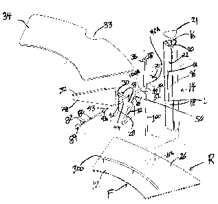
Shown in Figures 1 to 5 is a preferred embodiment of the desk assembly in
accordance with the invention. The desk assembly 10 has a front F and a rear
R.
A base 12 is preferably an approximately isosceles trapezoidal shape with a
concavely
curved inner side, and may be comprised of steel and is adapted to stably
engage a floor
surface. An upright support member, preferably an extruded aluminum column 14
defining a
hollow interior space 16, and having a vertical wall 18 is secured to the base
and extends
upwardly there from. The wall has inner 20 and outer 22 vertical surfaces. The
column may
include a removable cap 21 which may be press fitted into engagement with the
top of the
column.
Preferably the column 14 is secured to the base by means of screws (not shown)
extending through the base and into screw bosses 24 in the column 14 and the
column 14 is
positioned adjacent a rear edge portion 26 of the base.
- 3 -
CA 02406320 2002-10-02
Support means, preferably forwardly and diagonally extending brackets 28,
secured to
a carrier plate 30 are connected in slidable engagement along the column 14
between lower L
and upper U positions. Preferably the brackets have upper planar outwardly
extending
horizontal flanges 32 upon which planar desk top 34 may be attached. The desk
has a
rearwardly positioned groove 33 in which the column 14 may be positioned.
Although, it is
preferred that a planar desk 34 is supported by the brackets 28, it should be
understood that
any suitable work piece may be supported by the brackets.
In the preferred form, the range of movement of the desk top permitted by
movement
of the support means between L and U includes or at least corresponds to
positions of the
desk top 34 employed by users of normal height when in seated and in standing
positions,
respectively.
A sliding channel piece 36 defines a vertical channel 38, having a lower end
closed by
an end piece 36a, is positioned along the inner vertical surface 20, and
secured to the carrier
plate 30 by a connector screw 42. Preferably, the sliding channel piece is
guided along said
inner vertical surface 20 by means of guide ribs 41 formed integrally with the
inner vertical
surface 20 of the extruded column 14. The connector screw 42 connects the
carrier plate 30
and channel piece 36 so that the two move vertically in unison between the
upper U and
lower L positions. The connector screw extends rearwardly through a hole 44 in
said earner
plate, through a vertically extending slot 46 machined in the column vertical
wall 18 and in
threaded engagement with nut 48 welded to the inner face of the channel piece
in alignment
with a hole 49 formed through the channel piece 36. Vertical travel is limited
at the lower
position L by the connector screw 42 contacting the bottom of the slot 46 and
at the upper
- 4 -
CA 02406320 2002-10-02
position U by locking screw 43 contacting the top of the slot 46.
Preferably a wheel assembly 50 is rotatably mounted on each side of the
carrier plate
30. Each wheel assembly 50 is secured to the earner plate 30 by means of an
axle assembly
52 which extends through rearwardly extending side portions 54 of the earner
plate on each
side of the carrier thereof. Each portion 54 extends within a forwardly
opening vertically
extending channel 56 formed integrally with the vertical wall 18 of the
extruded column 14.
Preferably the brackets 28 are secured to the side portions 54 on each side of
carrier plate 30
and the portions 5.~ and brackets as well as channels 56 extend at an acute
angle with respect
to one another and with respect to a vertical plane of symmetry 55. Each wheel
assembly 50
comprises a pair of wheel members 60 rotatably engaged on said axle assembly
52. The
wheels are normally in rolling engagement with the column wall outer surface
within channel
56
A locking device is provided, preferably in the form of a clamp operable from
adjacent the desk top 34, to selectively secure the support means in positions
intermediate
said upper U and lower L positions. Preferably locking screw 43 extends
through the carrier
plate 30 and sliding channel piece 36 via screw bosses formed therein, and is
threadably
engaged within a tapped hole 70A in a clamp plate 70 which is positioned
adjacent said
sliding channel piece 36 rearward of said channel piece within the column.
Preferably, the
clamp plate 70 comprises a main portion 70B extending transversely of the
plane 55 and two
outwardly rearwardly incliding wing portions 70C each engaging and extending
parallel to the
inner surfaces 20 of the portions of the bases of the forwardly opening
vertically extending
channels 56. The locking screw 43 has an enlarged head 43a abutting the front
face of the
- 5 -
CA 02406320 2002-10-02
carrier plate 30 which prevents the screw from advancing through the Garner
plate. The
locking screw may be rotated to threadably engage the clamp plate 70. With the
head 43a
flush with the carrier plate 30, threadably engaging the clamp plate 70 with
the locking screw
head 43a deforms the Garner plate 30 resiliently into engagement with the
vertical wall outer
surface 22 and the resulting tension in the screw 43 presses the wings 70C of
the clamp plate
70 tightly against the inner side of the bases of the channels 56. In this
condition, the
frictional engagement of plates 30 and 70 with the column 14 locks the support
means 28 and
30 in a selected position in the range of movement between the upper U and
lower L
positions.
A rotatable locking rod 80 is supported by bracket 82, secured to and
extending from
the underside of said desk top 34 and has a forwardly positioned locking knob
84 for rotation
of said rod about its axis. The locking rod 80 is fixed to, for example with a
set screw (not
shown) passing radially through the head 43a, the head 43a so that rotation of
the locking
knob 84 rotates said the locking screw and thus allows locking of the support
means by
threading the locking screw 43 into the clamp plate 70 as described above by
rotation of the
knob 84 in one sense or release of the clamp plate 70 and Garner plate 30 by
rotation of the
knob in an opposite sense. It should be understood that any suitable locking
device may be
utilized to lock the desk in positions intermediate the upper U and lower L
positions. For
example, other clamping devices, could be used to selectively secure the
brackets, the carrier
plate or the channel piece to the column. While the above arrangement provides
infinite
adjustment within the permitted range, it is contemplated that the support
means could be
secured to the column 14 by locking pins, dowels or the like that allow the
support means to
be fixed to the column at a number of discrete positions in the range.
- 6 -
CA 02406320 2002-10-02
A upwardly biassing means, which is preferably a gas spring 100 is positioned
between and connected between the base and the desk, for providing upward
force sufficient
to lift said support means and desk from the lower L to upper U positions
without application
of upward force by the user. In particular, the gas spring 100 is preferably
positioned within
the column 14 below the sliding channel piece 36 and biases the latter
upwardly. Preferably
gas spring 100 includes an axially extending pin at each end. The lower pin is
seated in an
opening 112 in the base 12. At the upper end, the pin 100A is received in an
opening 36b in
the end piece 36a. Preferably the gas spring comprises a single-acting non
lockable piston,
that simply compresses the gas in the cylinder on pressing the desk top 34
down on
movement from U to L, the reaction against the piston providing the upward
force that lifts
the desk top 34 unassisted from L to U. The gas spring may be for example a
Suspa (TM) gas
spring, such as the Suspa 41090 available from Suspa Incorporated of Grand
Rapids,
Michigan, U.S.A. It should be understood that the upward biasing force could
be provided by
other means such as a compression spring or the like positioned in a same
manner or similar
to the gas spring 100 shown in the drawings.
In an alternate embodiment of the invention, the brackets 28 may be integrally
formed
with the carrier plate 30.
A monitor support bracket 122 may be mounted to the extruded column 14 or desk
34
for holding a computer monitor 400. A vertical partition member 124 may be
secured to
the extruded column 14, positioned rearwardly of the column to provide a sound
and
sight barner for the desk. A rail 300 acting as a foot rest for the user may
be secured
CA 02406320 2002-10-02
to the base 12
As will be apparent to those skilled in the art in the light of the foregoing
disclosure, many alterations and modifications are possible in the practice of
this
invention without departing from the spirit or scope thereof. Accordingly, the
scope
of the invention is to be construed in accordance with the substance defined
by the
following claims.
g _