Sélection de la langue

Search

Sommaire du brevet 2407346 

Énoncé de désistement de responsabilité concernant l'information provenant de tiers

Une partie des informations de ce site Web a été fournie par des sources externes. Le gouvernement du Canada n'assume aucune responsabilité concernant la précision, l'actualité ou la fiabilité des informations fournies par les sources externes. Les utilisateurs qui désirent employer cette information devraient consulter directement la source des informations. Le contenu fourni par les sources externes n'est pas assujetti aux exigences sur les langues officielles, la protection des renseignements personnels et l'accessibilité.

Disponibilité de l'Abrégé et des Revendications

L'apparition de différences dans le texte et l'image des Revendications et de l'Abrégé dépend du moment auquel le document est publié. Les textes des Revendications et de l'Abrégé sont affichés :

  • lorsque la demande peut être examinée par le public;
  • lorsque le brevet est émis (délivrance).
(12) Brevet: (11) CA 2407346
(54) Titre français: DISQUE SEPARATEUR DE COMPOSANTS SANGUINS
(54) Titre anglais: BLOOD COMPONENTS SEPARATOR DISK
Statut: Périmé et au-delà du délai pour l’annulation
Données bibliographiques
(51) Classification internationale des brevets (CIB):
  • B04B 01/00 (2006.01)
  • B01D 21/26 (2006.01)
(72) Inventeurs :
  • ELLSWORTH, JAMES R. (Etats-Unis d'Amérique)
  • LEVESQUE, STEVEN F. (Etats-Unis d'Amérique)
(73) Titulaires :
  • HARVEST TECHNOLOGIES CORPORATION
(71) Demandeurs :
  • HARVEST TECHNOLOGIES CORPORATION (Etats-Unis d'Amérique)
(74) Agent: SMART & BIGGAR LP
(74) Co-agent:
(45) Délivré: 2009-09-01
(86) Date de dépôt PCT: 2001-04-27
(87) Mise à la disponibilité du public: 2001-11-08
Requête d'examen: 2006-04-27
Licence disponible: S.O.
Cédé au domaine public: S.O.
(25) Langue des documents déposés: Anglais

Traité de coopération en matière de brevets (PCT): Oui
(86) Numéro de la demande PCT: PCT/US2001/011732
(87) Numéro de publication internationale PCT: US2001011732
(85) Entrée nationale: 2002-10-25

(30) Données de priorité de la demande:
Numéro de la demande Pays / territoire Date
60/200,150 (Etats-Unis d'Amérique) 2000-04-28

Abrégés

Abrégé français

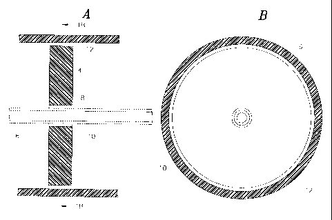
L'invention concerne un disque séparateur (4) utilisé pour séparer des composants de manière centrifuge, conçu de façon à se placer automatiquement pendant une séparation au niveau d'une interface entre le surnageant et les composants restants. L'interface est, de préférence, placée entre le plasma et les globules rouges.


Abrégé anglais


A separator disk (4) for use in centrifugal separation of components is
designed to automatically position itself during
separation at the interface between the supernatant and the remaining
components. Preferably the interface is between plasma and
red blood cells.

Revendications

Note : Les revendications sont présentées dans la langue officielle dans laquelle elles ont été soumises.


CLAIMS:
1. A combination comprising a tube comprising an inner wall forming a
cavity adapted to contain a physiological fluid to be subjected to
centrifugation and a
separator disk in said tube adapted to float freely in said physiological
fluid and
separate components of said physiological fluid having different specific
gravities,
said disk being made of a material having a specific gravity near the specific
gravity
of a first component of said physiological fluid and comprising a peripheral
portion
adjacent said inner wall of said tube and a central portion extending across
at least
a portion of said cavity, said central portion having an upper surface forming
a
closed recess configured such that after centrifugation of said physiological
fluid
said closed recess lies just below an interface formed by said first component
that
has been separated from other of said components and accumulates a small layer
of said first component.
2. A combination according to claim 1 wherein said disk fits into said tube
such that a gap is formed between the perimeter of said disk and the interior
of said
tube, said gap being of such a dimension that the component of said fluid
below said
disk after separation will not flow through said gap at about 1G.
3. A combination according to claim 1 further comprising a shaft extend-
ing along said tube and engaging said disk such that said disk slides along
said
shaft.
4. A combination according to claim 1 wherein said disk is arranged to
rotate about an axis transverse to the longitudinal axis of said tube to form
a valve
with the side of said tube during decanting.
5. A combination according to claim 4 further comprising a shaft extend-
ing along said tube and engaging said disk such that said disk slides along
said
shaft.
8

6. A combination according to claim 4 wherein said disk includes an
upper outer edge and a lower outer edge and the transverse dimension between
said upper outer edge and lower outer edge is greater than the internal
diameter of
said tube.
7. A combination according to claim 1 wherein said upper surface is
curved.
8. A combination according to claim 7 wherein said upper surface is
cylindrical.
9. A combination according to claim 1 wherein said disk is shaped such
that its center of buoyancy is located above said upper surface of the disk.
10. A combination according to claim 1 wherein said physiological fluid is
blood and the specific gravity of said disk is such that said upper surface
lies just
below an interface between plasma and red blood cells.
11. A method for separating a supernatant from a first component of a
physiological fluid comprising the steps of:
providing a tube comprising an inner wall forming a cavity adapted to contain
a physiological fluid to be subjected to centrifugation and a separator disk
in said
tube adapted to float freely in said physiological fluid and separate
components of
said physiological fluid having different specific gravities, said disk being
made of a
material having a specific gravity near the specific gravity of a first
component of
said physiological fluid and comprising a peripheral portion adjacent said
inner wall
of said tube and a central portion extending across at least a portion of said
cavity,
said central portion having an upper surface forming a closed recess
configured
such that after centrifugation of said physiological fluid said closed recess
lies just
below an interface formed by said first component that has been separated from
other of said components and accumulates a small layer of said first
component,
9

providing said physiological fluid to the container, and
subjecting said container and said physiological fluid to centrifugation.
12. A method according to claim 11 wherein said physiological fluid is
blood and said first component is red blood cells.
10

Description

Note : Les descriptions sont présentées dans la langue officielle dans laquelle elles ont été soumises.


CA 02407346 2002-10-25
WO 01/83068 PCT/USOI/11732
BLOOD COMPONENTS SEPARATOR DISK
TECHNICAL FIELD
This invention relates to methods and apparatus for use in the
separation of fluids into components having different specific gravities. The
invention finds particular utility in the centrifugal separation of the
components
of blood.
BACKGROUND
Centrifugal separation of blood into components of different specific
gravities, such as red blood cells, white blood cells, platelets, and plasma
is
known from United States Patent 5,707,331 (Wells). The apparatus shown in
that patent employs a disposable processing tube having two chambers, and
blood to be separated into components is placed in one of the chambers. The
processing tube is placed in a centrifuge, which subjects the blood to
centrifugal forces to separate the components. The supernatant is then
automatically decanted into the second of the chambers.
To retain, principally, the red blood cells during the decant of the
supernatant, the apparatus disclosed in the Wells patent includes a shelf
placed in the first chamber at the expected level of the interface between the
red blood cells and the less-dense components, including the plasma. One
problem with the arrangement shown in the `331 Wells patent, however, is
that the position of the interface varies with the particular proportions of
the
components (e.g., the hematocrit) of the blood to be processed. Thus, if the
1

CA 02407346 2002-10-25
WO 01/83068 PCT/US01/11732
shelf is placed at the expected position of the interface for blood of average
hematocrit, and the hematocrit of the particular blood being processed is low,
the shelf will be above the interface after separation. Such a position of the
shelf will hinder the flow of the components near the interface during
decanting, thus retaining significant amounts of these components in the first
chamber and reducing the separation efficiency of the system.
SUMMARY OF THE INVENTION
In accordance with the invention, a movable separator disk, which
automatically positions itself at the interface between the separated
components, is placed in the first chamber. In the preferred embodiment, the
disk is capable of moving vertically and is designed to position itself
automatically at the interface between red blood cells and the remaining
components in the centrifugal separation of blood.
Decant of the supernatant can be either by gravity drain or by
centrifugal transfer, and a main function of the disk is to restrict the flow
of the
component below it, e.g., red blood cells, during decant. This ensures that
the supernatant is not contaminated and increases the efficiency of the
process.
The invention contemplates two embodiments for the disk. In one
embodiment, the disk is supported on a central shaft such that an annulus is
formed between the perimeter of the disk and the interior surface of the first
chamber. The dimensions of the annulus are such that the flow of red blood
cells through it during decant is restricted such that they do not contaminate
the decanted supernatant to any significant degree.
2

CA 02407346 2002-10-25
WO 01/83068 PCT/US01/11732
In another embodiment, the disk is arranged on the shaft such that,
when the chamber is tilted for gravity decanting, the disk rotates such that
one
edge of the disk engages the wall of the chamber to block flow of red blood
cells.
In either of these embodiments, the specific gravity of the disk and its
shape may be chosen so that a major part of the upper surface lies just below
the interface, thus facilitating release of the supernatant from the disk
during
decanting. This upper surface is also preferably curved to match the
cylindrical shape the interface assumes during centrifugation.
BRIEF DESCRIPTION OF THE DRAWINGS
Figure 1 a is a longitudinal cross-section of a portion of a processing
tube chamber and a separator disk in accordance with a first embodiment of
the invention.
Figure 1 b is a transverse cross section taken along line 1 b-1 b of figure
1 a.
Figure 2a is a longitudinal cross-section of the embodiment of figures
1 a and 1 b when the separator disk is tilted during decanting.
Figure 2b is a transverse cross section taken along line 2b-2b of figure
2a.
Figure 3a is a longitudinal cross-section of a second embodiment of the
invention.
Figure 3b is a transverse cross section taken along line 3b-3b of figure
3a.
Figure 4 is a longitudinal cross-section of a third embodiment of the
invention.
3

CA 02407346 2002-10-25
WO 01/83068 PCT/US01/11732
DETAILED DESCRIPTION OF THE PREFERRED EMBODIMENTS
With reference to figures 1 and 2, one chamber 2 of a processing tube,
such as that shown in the `331 Wells patent has a separator disk 4 in
accordance with the invention supported therein by a central shaft 6. The
shaft 6 is designed to direct fluid introduced into the chamber to the bottom
of
the chamber. This precludes the formation of an air bubble at the bottom of
the chamber, particularly when the bottom of the chamber is tapered. Thus,
fluid is introduced into the chamber by inserting a cannula attached to a
syringe containing blood into the shaft 6 and discharging the blood from the
syringe into the chamber. A central opening 8 in the disk receives the shaft 6
in such a manner that the disk easily slides along the shaft.
The shaft 6 may not be necessary in all instances, for example, when
the bottom of the processing tube is flat. In that instance the disk does not
have a central hole.
The disk is preferably made of material having a specific gravity that
allows the disk to float at the interface with red blood cells. In the
preferred
embodiment that specific gravity is about 1.04 (e.g., polystyrene), which is
just
less than the specific gravity of red blood cells at 70% hematocrit. Thus,
when the blood is centrifuged, the disk moves to the interface between the red
blood cells and the other components.
The interface will naturally assume a cylindrical shape with a cylindrical
radius equal to the distance to the center of rotation of the centrifuge. The
disk may be cylindrical, to match the shape of the interface.
In the embodiment shown in figures 1 a, 1 b, 2a and 2b, the diameters of
the hole 8 and the shaft 6 are such that an annular gap 10 is formed between
4

CA 02407346 2002-10-25
WO 01/83068 PCT/USO1/11732
the outer surface of the shaft and the interior surface of the hole 8.
Similarly,
an annular gap 12 is provided between the perimeter of the disk and the
interior surface of the tube 2.
Figures 1 a and 1 b illustrate the position of the disk during
centrifugation, and it will be appreciated that the gaps 10 and 12 are large
enough to allow passage of the descending heavier components, e.g., red
blood cells and the ascending lighter components, e.g., plasma. According to
this embodiment, however, the diameter of the central opening 8 is large
enough whereby during decanting the disk 4 rotates as shown in the figures.
Thus, when the processing tube is rotated to the decant position, the more
dense red blood cells, illustrated at 14, that have accumulated below the disk
exert a force against the bottom of the disk as they try to flow through the
gap
12. This causes the disk 4 to rotate, as shown in figures 2a and 2b, until a
portion of the lower outer edge 16 of the disk and also the upper outer edge
18 engage the inner surface of the chamber 2. This engagement between the
edge 16 of the disk and the interior of the chamber effectively forms a valve
that prevents flow of the red blood cells, allowing decant of the plasma
supernatant without contamination by red blood cells. It will be appreciated
that this embodiment requires the transverse dimension of the disk between
edges 16 and 18 to be greater than the internal diameter of the tube so that
the edges engage the interior of the tube when tilted.
A second embodiment is shown in figures 3a and 3b. According to this
embodiment, the gap 10 is made to be small whereby the disk does not rotate
appreciably during decant, in contrast to the embodiment of figures 1 and 2.
It
will be appreciated that an annular channel is formed by the gap 12, this

CA 02407346 2002-10-25
WO 01/83068 PCT/USO1/11732
channel having a width equal to the radial dimension of the gap and a length
equal to the thickness of the disk at the edge. The rate of flow of a fluid
through this channel is a function of the dimensions of the channel, and the
dimensions of the disk of this embodiment are such that the red blood cells
will not flow appreciably through the channel at 1 G. In the preferred
embodiment, the width of the gap is about 0.005 inch to about 0.020 inch, and
the length is about 0.1 inch to about 0.3 inch.
Thus, the components of the blood flow through the channel during
centrifugation (i.e., at 1000G), but do not flow appreciably through the
channel
during decanting at 1 G. This allows the supernatant to be decanted without
significant contamination by the red blood cells.
Figure 4 illustrates a preferred shape of the disk 4. In this embodiment,
the top surface 20 of the disk is concave, preferably cylindrical, and the
disk is
provided with an elongated central portion 22. The specific gravity of the
disk
material is selected so that the concave surface 20 is located just below the
interface. That is, the thickness of the outer edge, the length of the portion
22, and the specific gravity of the material are chosen so that the center of
buoyancy of the disk is just above the concave surface, and that surface will
be just below the interface 26 with red blood cells. This arrangement allows a
small layer 24 of the red blood cells to form on the upper surface.
The layer of red blood cells 24 reduces the surface tension between
the platelets at the interface 26 and the surface 20 of the disk and
facilitates
release of the platelets from the disk. This is important to ensure that all
of
the platelets are decanted, and the small amount of red blood cells that may
6

CA 02407346 2002-10-25
WO 01/83068 PCT/US01/11732
be decanted along with the supernatant does not generally represent a
significant contamination of the supernatant.
Modifications within the scope of the appended claims will be apparent
to those of skill in the art.
7

Dessin représentatif
Une figure unique qui représente un dessin illustrant l'invention.
États administratifs

2024-08-01 : Dans le cadre de la transition vers les Brevets de nouvelle génération (BNG), la base de données sur les brevets canadiens (BDBC) contient désormais un Historique d'événement plus détaillé, qui reproduit le Journal des événements de notre nouvelle solution interne.

Veuillez noter que les événements débutant par « Inactive : » se réfèrent à des événements qui ne sont plus utilisés dans notre nouvelle solution interne.

Pour une meilleure compréhension de l'état de la demande ou brevet qui figure sur cette page, la rubrique Mise en garde , et les descriptions de Brevet , Historique d'événement , Taxes périodiques et Historique des paiements devraient être consultées.

Historique d'événement

Description Date
Le délai pour l'annulation est expiré 2015-04-27
Lettre envoyée 2014-04-28
Accordé par délivrance 2009-09-01
Inactive : Page couverture publiée 2009-08-31
Préoctroi 2009-06-15
Inactive : Taxe finale reçue 2009-06-15
Un avis d'acceptation est envoyé 2008-12-15
Lettre envoyée 2008-12-15
Un avis d'acceptation est envoyé 2008-12-15
Inactive : CIB enlevée 2008-12-09
Inactive : Approuvée aux fins d'acceptation (AFA) 2008-11-20
Modification reçue - modification volontaire 2008-04-29
Inactive : Dem. de l'examinateur par.30(2) Règles 2007-10-30
Lettre envoyée 2006-05-24
Exigences pour une requête d'examen - jugée conforme 2006-04-27
Requête d'examen reçue 2006-04-27
Modification reçue - modification volontaire 2006-04-27
Toutes les exigences pour l'examen - jugée conforme 2006-04-27
Inactive : CIB de MCD 2006-03-12
Lettre envoyée 2003-05-14
Inactive : Transfert individuel 2003-03-21
Inactive : CIB attribuée 2003-02-24
Inactive : CIB enlevée 2003-02-24
Inactive : CIB en 1re position 2003-02-24
Inactive : Page couverture publiée 2003-02-04
Inactive : Lettre de courtoisie - Preuve 2003-02-04
Inactive : Notice - Entrée phase nat. - Pas de RE 2003-01-31
Demande reçue - PCT 2002-11-26
Exigences pour l'entrée dans la phase nationale - jugée conforme 2002-10-25
Demande publiée (accessible au public) 2001-11-08

Historique d'abandonnement

Il n'y a pas d'historique d'abandonnement

Taxes périodiques

Le dernier paiement a été reçu le 2009-03-20

Avis : Si le paiement en totalité n'a pas été reçu au plus tard à la date indiquée, une taxe supplémentaire peut être imposée, soit une des taxes suivantes :

  • taxe de rétablissement ;
  • taxe pour paiement en souffrance ; ou
  • taxe additionnelle pour le renversement d'une péremption réputée.

Les taxes sur les brevets sont ajustées au 1er janvier de chaque année. Les montants ci-dessus sont les montants actuels s'ils sont reçus au plus tard le 31 décembre de l'année en cours.
Veuillez vous référer à la page web des taxes sur les brevets de l'OPIC pour voir tous les montants actuels des taxes.

Historique des taxes

Type de taxes Anniversaire Échéance Date payée
Taxe nationale de base - générale 2002-10-25
Enregistrement d'un document 2003-03-21
TM (demande, 2e anniv.) - générale 02 2003-04-28 2003-04-23
TM (demande, 3e anniv.) - générale 03 2004-04-27 2004-04-05
TM (demande, 4e anniv.) - générale 04 2005-04-27 2005-03-16
TM (demande, 5e anniv.) - générale 05 2006-04-27 2006-03-17
Requête d'examen - générale 2006-04-27
TM (demande, 6e anniv.) - générale 06 2007-04-27 2007-03-16
TM (demande, 7e anniv.) - générale 07 2008-04-28 2008-03-26
TM (demande, 8e anniv.) - générale 08 2009-04-27 2009-03-20
Taxe finale - générale 2009-06-15
TM (brevet, 9e anniv.) - générale 2010-04-27 2010-03-17
TM (brevet, 10e anniv.) - générale 2011-04-27 2011-03-17
TM (brevet, 11e anniv.) - générale 2012-04-27 2012-03-21
TM (brevet, 12e anniv.) - générale 2013-04-29 2013-03-21
Titulaires au dossier

Les titulaires actuels et antérieures au dossier sont affichés en ordre alphabétique.

Titulaires actuels au dossier
HARVEST TECHNOLOGIES CORPORATION
Titulaires antérieures au dossier
JAMES R. ELLSWORTH
STEVEN F. LEVESQUE
Les propriétaires antérieurs qui ne figurent pas dans la liste des « Propriétaires au dossier » apparaîtront dans d'autres documents au dossier.
Documents

Pour visionner les fichiers sélectionnés, entrer le code reCAPTCHA :


Pour visualiser une image, cliquer sur un lien dans la colonne description du document. Pour télécharger l'image (les images), cliquer l'une ou plusieurs cases à cocher dans la première colonne et ensuite cliquer sur le bouton "Télécharger sélection en format PDF (archive Zip)" ou le bouton "Télécharger sélection (en un fichier PDF fusionné)".

Liste des documents de brevet publiés et non publiés sur la BDBC .

Si vous avez des difficultés à accéder au contenu, veuillez communiquer avec le Centre de services à la clientèle au 1-866-997-1936, ou envoyer un courriel au Centre de service à la clientèle de l'OPIC.


Description du
Document 
Date
(aaaa-mm-jj) 
Nombre de pages   Taille de l'image (Ko) 
Dessin représentatif 2002-10-24 1 37
Abrégé 2002-10-24 1 60
Revendications 2002-10-24 3 80
Dessins 2002-10-24 4 126
Description 2002-10-24 7 235
Revendications 2008-04-28 3 92
Dessin représentatif 2009-08-18 1 25
Rappel de taxe de maintien due 2003-02-02 1 106
Avis d'entree dans la phase nationale 2003-01-30 1 189
Courtoisie - Certificat d'enregistrement (document(s) connexe(s)) 2003-05-13 1 107
Rappel - requête d'examen 2005-12-28 1 116
Accusé de réception de la requête d'examen 2006-05-23 1 176
Avis du commissaire - Demande jugée acceptable 2008-12-14 1 163
Avis concernant la taxe de maintien 2014-06-08 1 170
PCT 2002-10-24 11 396
Correspondance 2003-01-30 1 24
Taxes 2003-04-22 1 29
Taxes 2004-04-04 1 32
Taxes 2005-03-15 1 27
Taxes 2006-03-16 1 27
Taxes 2007-03-15 1 29
Taxes 2008-03-25 1 31
Correspondance 2009-06-14 1 33
Taxes 2009-03-19 1 38