Note : Les descriptions sont présentées dans la langue officielle dans laquelle elles ont été soumises.
CA 02409097 2009-01-05
1
TINE SY87rErt
Beckeround of the Invvti.on
1. Field of tfie Iavention
This invention relabes to agricnlbaai tiltage equipmmant and, in pa¾dcuIar,
this
inveation relates to a tine and tine system for $eratimg soils with mdnimal
dismption of the
soil proSle.
u
2. Sacktronnd of iIows 3mrontioa
Pessons producing crops are often confromted with two issues: soil compaction
and
soil e,tosion. Solutions to these issues are often contradictory in nature.
Soii compacuion
ocrsas due to stiah pheaamaia ae zainfail, ovedead isxigation, tftge
haptements (e.g.,
2o krsctora, planters, cultivators), and Iivestoalt. Soil oompection causes
problems such as
redoced wsbmr iafilirs#ion, restricted ciop toat giavvth, and lovvra amnomnts
of oxrgen for
generai plant growth and deve3opmetrt. Tiiiago methods, such as moldboard
plowing, were
traditionally used to elmnste andfor reduce soil compaction. Howcvea,
moldbos,rd plows
typicallyleft the soil surfacebare and exposcd to wind and water erosion. To
redwx soil
25 erosion, compaction was often elimiaaud by using other titlago implements
with sweeps or
CA 02409097 2002-11-14
WO 01/87042 PCT/US01/15729
2
chisel-points. These implements had the advantage of leaving surface crop
residue more-or-
less intact to reduce soil loss due to erosion. However, the root structure of
the crop plant
residue was totally disrupted when these implements were used. Moreover,
tillage practices
with these implements often adversely affected trafficability and resulted in
increased soil
bullc density.
Without intending to limit the present invention, it is believed that silt
soil particles
are only slightly heavier than water. As water moves downward in a soil
profile, the water
transports silt particles with it, e.g., within the A-horizon. As the downward
movement of
water slows, the silt particles are deposited within the A-horizon to form a
nearly
indistinguishable layer initially. As this process continues over time, e.g.,
with additional
precipitation, this layer becomes discrete and identifiable. Mechanical
analysis of soil
profiles verifies that silt accumulates over time at different depths, in
differing soil types,
with differing organic matter content, and root system environments. The
creation and
existence of this "density layer" (or accumulated silt) is one condition
requiring tillage
operations. Perforation of this silt layer and fracturing of the same restores
more rapid water
intake of soils. It is not necessary to lift, turn, and/or redistribute the
silt in the A-horizon to
restore water movement. Aeration of soil is, in fact, a true tillage since one
of the major
functions of tillage is to restore the water intake capability of a given
soil. The accumulation
of silt serves as a barrier to the exchange of water and soil atmosphere
within a given soil.
2o The importance of this phenomenon in causing sheet erosion in no-till
situations and gully
erosion in cases of traditional primary tillage tecluuques is directly related
to the importance
of the present invention.
In addition to the concerns stated above, moldboard plows and chisels are
unsatisfactory in aerating soil profiles in which stands of perennials (e.g.,
pasture grasses,
alfalfa) have been established. Obviously, using moldboard plows or chisels
would destroy
SUBSTITUTE SHEET (RULE 26)
CA 02409097 2009-01-05
. i,
3
the stand ofperanniale, as weII as pobentialiy expose tbe sarface of the soil
to wind and water
eroeion. Howenrex, soil compaotioa frequentl,y occm in soib wiih pereoooial
caap stamds due
bo the effects of zain, iarigation, livestock braflicy' tractore and ba)nmg
eQaipmaat; and the like.
U.S. Patent 4,383,580, issued 17 May 1983 to Hux:ford 7
disclmea an agricultiual implement asec.rbed as being euitable lbr aerating
soils aud
paeNres. The agriculturat implement iactndea a frame attac2-abie ta aftee-
point traetor
linkage, a plnrality of ahatb rotatably moumted on tlxo fra e, and a pleality
of cuttang bladas
projecting from each of ihe rollers. The blades are formed from plate material
and are
preferably fotmed to apoint. Various edges of the blade are pmfaably doubled
to assist tHe
to implement in cuttiug the soil without undue liRing or tearing of!$e soil
snrface.
U.S. Patent 4.619,329, issued 28 Oatober 1986 to GoLbett }
disciases a soil aaator with a fiame. A rrotstabla drum is mout:yted on t3ie
frame.
The enolosed opposing ends of tlw dnun cstty axles, which ara mounted within
the frame,
arheoeby the drum is rotatable with respeet to tha ftne about the longttudinal
mds of tho
drum. A plurality of triangnlar-sbaped teeFh are arrmged in rows on an outer
c}rmdrioal
sarface of tba dxunL Each of the rows of toeth forms a cfievmn-shaped pattern
with respect to
$ie next euoceeding row of toeth.
U.S. Patant 4,840,232, issasd 20 June 1989 to Mayex )
diaeloses soil aesttn8 equigmetit having a frame and at least one pair of
sbafla.
zo The shsfts are freely and rotatably mmmted on the fizttne for rotataion
about &e shaft
longitadinal axes. The sl>afts extend in ioatwardly incliaed, opposite
directions from a
centerlin.e of the frama The resrward inclination of the shatts is adjustable
to desired angles
in the r=mga of from about 90 degines to about 120 degmw to the direction of
traveL Each
shaft carriea a series of soil-engsging, snbstamially plscer tines exteading
therefmm in
vertical planes and positionied to seqaentigly amg,age sad paaehate t6e sot'I
with consequent
CA 02409097 2009-01-05
s
4
rotation of the shafts when tbe fisane is moved in the duection of ttaveL Each
t~me has a
eentral, iongitndinal axia, whiah eatmds bebind iiie sba8 rotational aais at a
distawe
tberefrom in the raqge of about 0.25 to about 1.75 inab. Each tine is twisted
about a tine
central, tongitudinal axis at a fixed angle to a vertical plane parallel to
the direction of tiavei
in the range of from about 1 dogree to about 30 degreos.
U.S. Patent 5,020,602, issued 4 Juae 1991 to I)eltinger
discloses an aeasim for lawns and tho IiYe. The acrator has spiden fonned from
four identicall}-foime8 membc.rs. Ba& of thCSe merobeas bas a tine on each
end. Tiareore,
four members provid.e eight tines for tke apider. The menlbecs are relaiively
natrow. F'illa
to members at eacb end of tbe tine mecnbers provide stability to the spider.
The spidem are
catrind by a frama The fime cardea a weight-znooiving tray for earryiag weight
to assure
penctcation of the tines. Springs carry the tray on the fimne, so that die
springs will absorb
energy resulting fnm engaging an impanobvhbk object.
U.S. PaLeat 5,460,229, issued 24 October 1995 to Mattis
is discloses a$eld aeratoc apparatus asserted as being useful for aerating
gcass or hay
ground. The apparatus includes elongated spOces on a cylindrical drum. As the
apparatus is
towcd across a fiald, tho spilcas paaotrata and loosen the soil, as weII as
py'rovide opening,a in
ft soil to impmve water pemtration and reduce wattw ran-0$ The spdces are
seeuaed bo
bands encircling the dn.un. The spacing between bands is adjustable, so that
the spacing
20 between spikes can be adjusted.
U.S. Patent 5,611,291, issued 18 March 1997 to Pogue f
disctvses an aerator sud seeder for cmtilled paatana land. Tbe implement
inclndes a
frame and a cyiitutrieal dnmv. The drum is rotatabfy mounted on the Sane by a
co-rotatablo
aa" s6afft. A plmslityofrigid prongs are provided on the cylindrical svrface
of the dnun.
CA 02409097 2002-11-14
WO 01/87042 PCT/US01/15729
The prongs penetrate, agitate, and aerate the soil as the drum is rolled over
the land to be
seeded.
Many of the above-referenced documents are directed to reducing exposure of a
soil
to the erosion and enhancing trafficability thereon. The implements described
use tines
5 performing vertically to penetrate the soil profile, thereby reducing or
eliminating soil
compaction and aerating or restoring nonnal air-water exchange in the soil
profile as well.
These implements further minimize exposure to erosion by retaining above-
ground and
below-ground crop residue. However none of the implements described in these
documents
1) provides tines without abrupt radius changes; 2) provide a tine with a
cavity (and optional
soil retaining surfaces thereon) to catch soil and thereby abrade soil on the
surface of the tine
against soil being aerated; 3) provide a tine assembly with a key slot on both
sides of the tine
base to enable the tine to be reversibly mounted; and 4) provide a tine with a
slot or opening
for injecting fluids (e.g., fertilizer) into the soil during an aeration
procedure.
Summary of the Invention
This invention substantially meets the aforementioned needs of the industry by
providing a tine to aerate soils without destroying above-surface or below-
surface plant
residue. The mounted tine may be adjustable with respect to degree and
direction of rotation
2o and inclination. An aerator implement of this invention includes tines
mounted at any desired
degree and direction of rotation and at any desired degree of inclination with
respect to the
aerator implement centerline. The tine includes base and blade portions. The
tine base
portion may include an arcuate slot or key way, optional radial slots, and a
plurality of holes.
The arcuate slot enables the tine to be reversibly mounted so that either of
two blade edges
will initially engage soil being aerated. The holes accommodate fasteners such
as bolts and
SUBSTITUTE SHEET (RULE 26)
CA 02409097 2002-11-14
WO 01/87042 PCT/US01/15729
6
optionally provide an egress for fluids being applied to the soil, such as
fertilizer. The radial
slots provide a surface to further secure the tine against rotational forces
when in use. The
tine blade portion may include a soil retaining surface geometry, such as a
concave portion,
to catch some of the soil being aerated. The concave portion (as well as other
blade surfaces)
may also have soil retaining surface geometry, such as a raised grid to catch
some of the soil
being aerated, so that abrasive wear on the tine blade is minimized by
abrading soil-against-
soil, rather than abrading soil against the tine blade. The tines may be
mounted with a
desired degree and direction of rotation by using shims. The shims may include
surfaces
contoured to mate with the slot and holes in the tine base portion. The shims
may be tapered
at a desired angle to provide the desired degree of twisting or rotation. The
shims may also
be tapered to provide a desired degree (extent) of tine inclination.
Liquids, such as fertilizers, may be injected into the soil being aerated by
the present
aerator. The liquids are conveyed to the rotating tines by using a metering
spacer, metering
ring, and a band. The metering spacer rotates with the implement axle. The
metering ring
and band are stationary. The metering spacer defines a groove and a plurality
of lumens
opening into the groove. The metering ring has a slot. The band maintains the
metering
spacer and ring in an operative relationship, in which the metering ring is
disposed around the
metering spacer groove. A tube extends through the band and opens proximate
the slot.
Fluid to be applied is conveyed through the tube, then through the slot. From
the slot, the
fluid enters the spacer groove. From the spacer groove, the fluid is conveyed
to the tines,
through the spacer lumens. The fluid is forced through the holes in the
present tines onto
slots defined in the tine blades, from where the fluid is injected into the
soil profile. The fluid
is injected into the soil profile at a point below the soil surface via the
tine injection slot.
Injection of fluids below the soil surface prevents loss of nutrients from
volatilization and
runoff. Reduced or eliminated nutrient loss from runoff greatly minimizes
surface water
SUBSTITUTE SHEET (RULE 26)
CA 02409097 2002-11-14
WO 01/87042 PCT/US01/15729
7
pollution from such nutrient minerals such as phosphate and nitrogenous
compounds. In at
least one tine configuration, wherein soil is uplifted by tines when being
aerated, the present
aerator further prevents loss of nutrients by further covering applied
nutrients with soil
uplifted from below the soil surface.
A desired number of the tines are radially mounted in a set between two hubs,
the
hubs being fixed (or integral) to axles. A desired number of sets connected to
axles thusly are
said to form a gang. The tines may be mounted so that the tines are in a
helical arrangement
as an entire gang of tines is viewed. The mounted tines may be rotated
clockwise or
counterclockwise and may further be inclined toward, away from, or
perpendicular to, the
implement centerline in a desired configuration. Alternatively, the ends of
the present tines
may be angled at a bend in the tine, so that the mounted tines bend toward or
away from, the
implement centerline.
It is therefore an object of this invention, to provide a tine without abrupt
radius
changes in the body of the tine to thereby avoid concentrated shear forces
otherwise present
because of the tine design. Sharp radius changes between the blade and the
base in existing
art result in excessive breakage, especially in adverse or rocky conditions.
A further object of this invention is to provide a tine with a concave surface
to retain
soil on the concave surface of the tine blade and thereby minimize abrasive
wear on the tine
blade by abrading soil-against-soil, rather than soil against the tine blade.
A yet further object of this invention is to provide a tine with base surface
features
enabling the tine to be reversibly mounted on an aerating implement. These
features may
include a generally arcuate basal edge, bolt holes, one or more opposing
arcuate grooves and
one or more opposing radial grooves.
A yet still further object of this invention is to provide a tine with soil
retaining
surfaces, such as raised grids, which will retain soil. The retained soil on
the soil retaining
SUBSTITUTE SHEET (RULE 26)
CA 02409097 2002-11-14
WO 01/87042 PCT/US01/15729
8
surfaces diminishes tine wear because an appreciable amount of the abrasion
encountered by
the tine during use is soil-to-soil abrasion. A lesser amount of the abrasion
encountered by
the tine during use is tine-to-soil abrasion.
A still further object of this invention is to provide a tine, which can
inject fluids such
as fertilizers into the soil when the soil is being aerated by the tine. The
fluids may be
injected into the soil profile to prevent loss by volatilization or runoff
otherwise occurring if
the fluids were left on the soil surface. In some tine configurations, loss of
applied fluids is
further minimized by soil being deposited on the soil surface due to the soil
uplifting function
of the tines.
These and other objects, features, and advantages of this invention will
become
apparent from the description which follows, when considered in view of the
accompanying
drawings.
Brief Description of the Drawings
Figure 1 a is a plan view of a first side of two embodiments of the present
tine;
Figure lb is a plan view of a second side of the two tine embodiments of
Figure 1;
Figure lc is a side view of the first embodiment of the tine of Figure 1;
Figure 2 is a perspective view of the base portion of the second tine
embodiment of
Figure 1;
Figure 3 is a perspective view of a first lateral side of one embodiment of a
shim of
the present invention;
Figure 4 is a plan view of a second lateral side of the shim of Figure 3;
Figure 5 is a view of a first end of the shim of Figure 3;
Figure 6 is a view of a second end of the shim of Figure 3;
SUBSTITUTE SHEET (RULE 26)
CA 02409097 2002-11-14
WO 01/87042 PCT/US01/15729
9
Figure 7 is a perspective view of an axle and hub used to mount the present
tine;
Figure 8 is a plan view of one embodiment of the present tine and sliims of
this
invention mounted between two hubs of an aerator;
Figure 9 is a perspective view of one embodiment of a fluid metering spacer of
this
invention;
Figure 10 is a perspective view of a fluid metering ring of this invention;
Figure 11 is a cross sectional view of the metering ring of Figure 10 operably
disposed about the spacer of Figure 9; and
Figure 12 is a side view of a spacer of the present invention.
It is understood that the above-described figures are only illustrative of the
present
invention and are not contemplated to limit the scope thereof.
Detailed Description of the Invention/Drawings
Comprehension of this invention can be gained through reference to the
drawings in
conjunction with a thorough review of the following explanation. Any
references to such
relative terms as front, back, right, left, top, bottom, upper, lower,
horizontal, vertical,
inboard, outboard, and the like, are intended for convenience of description
and are not
intended to limit the present invention or its components to any one
positional or spatial
orientation. All dimensions of the components in the attached figures may vary
with a
potential design and the intended use of an embodiment of the invention
without departing
from the scope of the invention. Unless stated otherwise, relative
descriptions of tine rotation
angles and inclination with respect to the present aerator implement are from
the perspective
of the direction of travel andlor an aerator implement centerline.
SUBSTITUTE SHEET (RULE 26)
CA 02409097 2002-11-14
WO 01/87042 PCT/US01/15729
The first embodiment of the tine of this invention is depicted in Figures l a
and lb
generally at 100. The tine 100 is unitary (or otherwise integral) in this
embodiment, but may
be considered to include a base portion 104 and a blade portion 106. The tine
100 displays a
first side (surface) 108 and a second side (surface) 110. With respect to the
blade 106, the
5 tine 100 displays a first edge 112 converging with a second edge 114 at a
tip 116. With
respect to the base 104, the present tine displays a third edge 118. The third
edge 118
converges with a fourth edge 120 and a fifth edge 122 at 124 and 126,
respectively.
Referring particularly to Figure 1 a and viewing the first side 108 of the
tine 100, an
arcuate slot 130 and holes 132 and 134 are defined in the base 104. In this
embodiment, the
10 slot 130 extends between the fourth and fifth edges 120 and 122, generally
following the
arcuate contour of the third edge 118. At least a portion of the blade portion
of the first side
108 is configured as a soil retaining surface geometry by being "dished-out"
to a concave
surface 136. A raised portion (or more generally a soil retaining surface
geometry), such as a
grid 138, is present within the concave 136 in this embodiment. With reference
to the view
of the second side 110 of the tine 100 depicted in Figure lb, the base portion
104 defines an
arcuate slot 146, which extends between the fourth and fifth edges 120 and 122
and generally
follows the contour of the third edge 118. At least in part, the holes 132 and
134 extend
between the surfaces defined by the slots 130 and 146. A slot 150 is defined
in the blade and
base portions of the second side 110. The slot 150 slopes from the surface of
the second side
110 and opens into the hole 134. As will be seen below, a lumen (tunnel)
extending between
the hole 134 and the surface of the second side 110 could be present in lieu
of the slot 150.
Referring to Figures 1 a and lb, a first bevel 154 extends between the first
edge 112 and the
second side 110. A second bevel 156 extends between the second edge 114 and
the first side
108. In the embodiment depicted, a raised pattern (or more generally a soil
retaining surface
geometry), such as a grid 158, is present on the surface of the first bevel
154.
SUBSTITUTE SHEET (RULE 26)
CA 02409097 2002-11-14
WO 01/87042 PCT/US01/15729
11
Figures la, 1b, and 2 depict a second embodiment of the present tine generally
at 200.
The tine 200 is unitary (or otherwise integral) in this embodiment, but may be
considered to
include a base portion 204 and a blade portion 206. The tine 200 displays a
first side
(surface) 208 and a second side (surface) 210. Respective first and second
edges 212 and 214
extend from a tip 216 to define, in portion, the blade 206. The base portion
204 displays a
third edge 218, which converges with respective fourth and fifth edges 220 and
222 at 224
and 226. Radial slots 227, 228, and 229, an arcuate slot 230, and holes 232
and 234 are
defined on the first side 208 in this embodiment. The arcuate slot 230
generally follows the
contour of the third edge 218 and extends between edges 220 and 222. The slots
of the
present tine base, such as 130 and 227-230, represent contours used to secure
the present tine
in place. However, in place of depressions, such as the slots 130 and 227-230,
the present
tine may also include raised surfaces. Although not depicted, a raised
surface, such as the
grid 138 could be present at each of the sides 208 and 210. However, in the
embodiment
depicted as tine 200, a generally intersecting linear grid 238 of grooves is
inwardly defined
from the surface 208. A portion of the tine blade 206 may be "dished-out" to
form a soil
retaining surface geometry, such as a concave surface 236 on the first side
208 in the blade
portion 206. With respect to the second side 210, the base portion 204 defines
radial slots
240, 242, and 244 and an arcuate slot 246. The holes 232 and 234 extend
between the
surfaces defined by the slots 230 and 246 in this embodiment. The arcuate slot
246 generally
follows the contour of the third edge 218 in this embodiment. As best seen in
Figure 2, the
slots 227, 228, and 229 are generally opposite the respective slots 244, 242,
and 240.
Moreover, the arcuate slots 230 and 246 are generally opposed as well.
Although not shown,
the generally opposed relation between the slots 130 and 146 of the tine 100
is the same, or
substantially the same, as depicted in Figure 2 with respect to the arcuate
slots 230 and 246.
A slot 250, more fully discussed below, extends from the hole 232 to the
surface 208. A first
SUBSTITUTE SHEET (RULE 26)
CA 02409097 2002-11-14
WO 01/87042 PCT/US01/15729
12
beve1254 extends from the second side 210 to the first edge 212 and a second
beve1256
extends from the second side 208 to the second edge 214. A soil retaining
surface geometry,
such as a grid 258, may be defined on the first beve1254 In this embodiment,
the grid 258
represents a series of intersecting, substantially linear depressions.
There are no abrupt radius changes from the base portion to the blade portion
of the
present tine. Hence no radial fracture forces are generated because of the
lack of abrupt
radius changes. Figure 1c depicts a side view of the tine 100. A portion of
the concave 136
generally coinciding with a longitudinal axis of the tine is indicated in
phantom. In contrast
to the tines of the prior art, present tine gradually transitions from a base
thickness 302 to a
minimum concave thickness 304. In the embodiment depicted, the transition from
the base
thickness to the minimum concave thickness can be characterized by an angular
relation from
the transition point 306 to the point 308 at which the thickness is at a
minimum. The point
308 may also be characterized as the point nearest the transition point 306 at
which the
thiclmess is at a minimum. The transition point is considered to be the
position along the
longitudinal axis at which the thickness of the present tine begins to
decrease. The
transitioning of the present tine, as described above, may be further
characterized by an angle
310 describing the angular relation between lines 312 and 314. The line 312
extends between
the transition point 306 and the point of minimum thickness 308. The line 314
describes the
generally horizontal contour of the surface of present base portion. The angle
310 maybe
between about I degree and 20 degrees, between about 5 degrees and 15 degrees,
between
about 7 degrees and 13 degrees, or about 10 degrees. Stated otherwise, and by
way of
illustration and not limitation, for a tine of this invention with a length of
about 8.75 inches, a
base portion with a thickness of about 0.8 inches tapers to a minimum blade
(concave)
thickness of about 0.5 inch at a radius of about 8 inches, at a radius between
about 6 inches
and 10 inches, or at a radius between about 4 inches and 12 inches. The
transitioning
SUBSTITUTE SHEET (RULE 26)
CA 02409097 2002-11-14
WO 01/87042 PCT/US01/15729
13
described above imparts a resistance to the breakage frequently encountered
with respect to
tines of the prior art.
Referring to Figures 3-6, the present invention includes an angle-adjusting
device,
depicted as a shim 400. The shim 400 displays opposed respective first and
second lateral
surfaces 404 and 406, generally arcuate lower and upper surfaces 408 and 410,
and
substantially flat end surfaces 412 and 414. A raised portion 418 extends from
the first
lateral surface 404. Holes 420 and 422 extend between the raised portion 418
and the second
lateral surface 406. While the raised portion 418 is generally continuous in
this embodiment,
it may be considered to include an arcuate section 424 and optional radial
sections 426, 428,
and 430. The holes 420 and 422 align with holes 132 and 134 of tine 100 and
with holes 232
and 234 of the tine 200. The raised section 424 is disposed and dimensioned to
be received
in arcuate slots 130 or 146 of the tine 100 or arcuate slots 230 or 246 of the
tine 200. If the
radial grooves are present in the present tine base, the radial sections 426,
428, and 430 are
disposed and dimensioned to be accommodated in the radial sections 227, 228,
229, 240, 242,
and 244. Angles 432 434 may, in part, define the dimensions of the shim 400.
The angle 432
defines the arc through which the shim 400 extends, e.g., 90 degrees. The
angle 434 defines
the spacing of the holes 420 and 422, e.g., 30 degrees. If the tine of this
invention uses raised
surfaces rather than slots, the present angle adjusting devices would be
modified to define
depressions, which would mate with the tine raised surfaces.
Referring to Figures 4, 5, and 6, the shim 400 is depicted, displaying the
substantially
smooth shim surface 406 and a taper from end surface 412 to end surface 414.
In the absence
of a taper, a planar dimension of the present tine is generally perpendicular
to the axis of the
axle to which the tine is mounted. A nonlimiting recitation of the extent of
taper will enable
the present tine to be mounted so that the tine plane is rotated to a desired
extent, either
cloclcwise or counterclockwise, with respect to the axis of the axle to which
the tine is
SUBSTITUTE SHEET (RULE 26)
CA 02409097 2002-11-14
WO 01/87042 PCT/US01/15729
14
mounted. By way of illustration and not limitation, one such extent of
rotation is a multiple
of 2.5 degrees, e.g. 2.5 degrees, 5.0 degrees, 7.5 degrees, and 10.0 degrees.
The thickness t
of the shim 400 changes along the shim length 1 and remains substantially
uniform with
respect to the shim width w. However, a tapering width w may be present in
some
embodiments of the present shim. A tapering width will enable the present tine
attitude
(direction and extent of tipping) to either be toward, or away from, a
centerline of the aeration
implement. The significance of tine attitude will be discussed below.
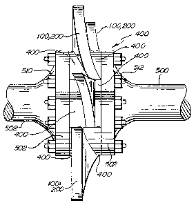
Referring to Figures 7 and 8, the present tines are advantageously mounted on
an
aerator with a plurality of axles 500. Each axle end terminates in a hub 502.
Each of the
hubs 502 displays respective inboard and outboard surfaces 504 and 506 and
defines a
plurality of holes 508, which extend between the surfaces 504 and 506. Now
referring
particularly to Figure 8, the present tines and shims are deployed to achieve
a desired extent
of rotation as described above. In the example depicted in Figure 8, the
present tines 100,
200 are mounted between two of the present shims 400 so as to impart the
desired degree of
rotation to the tine planes. The shims 400, in turn, are disposed between
inboard surfaces 504
of hubs 502. The tines, shims, and hubs are fixed into place with fasteners,
such as bolts 510
(extending through the holes 132, 134, 232, 234, 420, 422, and 508 ) threaded
onto nuts 512.
The combination of the reversible shims and reversible tine of this invention
enables a high
degree of versatility of mounting options. The present tine can be mounted
such that it 1)
inclines toward or away from the implement centerline; 2) is rotated toward or
away from the
implement centerline; and 3) is in either the forward or rear position.
Therefore, at least eight
mounting configurations are possible with each shim combination.
Suitable materials for use in making the present tine and shim include ductile
iron and
carbidic ductile iron, each optionally undergoing a tempering, such as an
austemper protocol
to a grade 51eve1 of hardness, after the tines and shims have been formed.
SUBSTITUTE SHEET (RULE 26)
CA 02409097 2002-11-14
WO 01/87042 PCT/US01/15729
As shown in Figures 9-11, the present aerator may be used to apply a fluid by
including a metering spacer 550 and a metering ring 552 of the present
invention. The
metering spacer 550 and metering ring 552 depict an optional liquid metering
system,
wherein fluids (e.g., fertilizers) are placed below the surface of a soil
profile by the present
5 aerator implement during an aeration procedure.
Referring to Figure 9, the generally cylindrical spacer 550 defines a
plurality of
generally axial lumens 556, each lumen 556 extending between respective
inboard (intake)
and outboard ports 558 and 560. The inboard ports 558 open into a generally
circumferential
groove 562. In this embodiment the number of lumens is determined by the
number of
10 injection sites, e.g., the number of tines. Diameters of the lumens 556 are
determined by such
factors as the amount and viscosity of the fluid to be applied.
Figure 10 depicts one embodiment of the present metering ring at 552, which
includes
ring portions 566 and 568. The ring portion 566 defines a liquid transport
tube groove 570
and an optionally variable length metering slot 572. Increasing slot lengths
will increase the
15 exposure time of the lumen inboard (intake) ports to fluids being applied.
Thus, by
increasing the length of the metering slot, the present metering ring will
dispense increasing
quantities of liquids. Specific quantities of fluids dispensed depend on such
factors as
temperature, pressure, implement speed, and the viscosity of the fluid being
dispensed.
A cross-sectional depiction of the metering ring 552 and a band 573 is shown
in
Figure 11, wherein "C," "B," and "A" depict increasing lengths of the slot
572. The metering
spacer 550 would be enclosed within the metering ring 552, but is omitted in
Figure 11 for
clarity. A tube 574 extends through the band 573. An end 575 of the tube 574
is disposed at
least partially within the groove 570 of the ring portion 566. The fluid to be
dispensed is
conveyed from a pressurized source (not shown), through an ingress end 576 of
the tube 574,
out through the tube end 575, and through the slot 572. The fluid then enters
the spacer
SUBSTITUTE SHEET (RULE 26)
CA 02409097 2002-11-14
WO 01/87042 PCT/US01/15729
16
groove 562, from which the fluid enters the lumens 556 via the inboard ports
558. The
lumens 556 convey the fluid to tine locations. At the tines, the fluid is
dispensed into the soil
by being forced through one of the orifices at the base of the present tine
and out the slot 150
or 250. Each lumen may supply more than one tine location. Alternatively,
elimination of
the outlet in the tine base area can permit selecting specific locations for
injection while
eliminating other locations. The spacer 550 and metering ring 552 are
lubricated by means of
a lubrication fitting, such as a zerk 577, and a lubricant slot 578. In this
embodiment, the
zerk 577 is disposed in the band 573 and the lubricant slot is defined in the
ring portion 568.
The band 573 may be secured around the ring sections 566 and 568 and the
spacer 550 by a
fastener, such as a screw or bolt (not shown) extending through the lips 580
and 582.
Figure 12 shows one embodiment of a generally unitary spacer of this invention
generally at 590. The spacer defines orifices 592, which may be dimensioned
and positioned
to be in registry with the lumens 556 of the spacer 550. A generally circular
raised portion
594 intersects optional radial raised portions 596. The raised portion 594 is
dimensioned and
positioned to fit into the arcuate slot present in the base of the present
tine. The raised
portions 596 are dimensioned and positioned to fit into the radial slots
present in some
embodiments of the present tine base. Another generally circular raised
portion 598 is
disposed outside an orifice 599. The raised portion 598 aligns with the third
edges of the
third edges 118 and 218 of the present tine. The spacer is secured in place
using a fastener
such as an arbor bolt extending through the orifice 599. Alternatively, the
raised portions
may be substituted for depressions or grooves if the present tine includes
raised surfaces in
lieu of slots. The spacer 590 may be used in the place of the present shims.
If used in place
of the shims described herein, a pair of the spacers 590 could have sloped
portions present in
the raised surface 594, rather than the smooth surface depicted.
SUBSTITUTE SHEET (RULE 26)
CA 02409097 2002-11-14
WO 01/87042 PCT/US01/15729
17
In one embodiment, the present tines are mounted on the hubs as depicted
above, such
that the edge 112 or 212 becomes the "leading edge" by entering the ground
first. After the
tine reaches a vertical position at 90 degrees (6 o'clock) within the soil,
the edge 114 or 214
becomes the leading edge, wherein the edge 114 or 214 and optionally one of
the blade
surfaces begin to fracture the compaction zone by cutting into the soil and
uplifting some
portion of the soil onto the soil surface. The amount of soil fractured and
uplifted is
determined in part by the tine attitude and degree of rotation. Pluralities of
the present tines
are functionally mounted to axles to comprise a gang of several tine sets. The
gang axles
may be deployed so as to be generally perpendicular to the direction of
travel. Alternatively,
the gang axles may be deployed at an angular departure to the perpendicular.
Soil fracturing
and uplifting will usually be increased as the present gang axle is angled
away from a
perpendicular deployment. Thus, another factor determining the amount of soil
fracturing
and uplifting is the angle at which a gang of the present tines is deployed.
Partially because the arcuate grooves in the base of the present tine may
extend
between the fourth and fiftll edges as described above, the present tine may
be reversed. In a
reversed position the edge 114 or 214 becomes the leading edge as the tine is
rotated into the
soil and the edge 112 or 212 becomes the leading edge as the tine is rotated
out of the soil.
Reversing the present tine may cause more soil to be uplifted and deposited on
the soil
surface, thereby minimizing volatilization loss of some applied fluids, e.g.,
anhydrous
ammonia. The concave surface and gridding cause soil to adhere to the tine
surface. Soil
adhering to the tine surface then abrades against soil particles in the soil
profile being aerated
when the tine is rotated into and out of the soil. Thus, the concave surface
and gridding
prolong the useful life of the present tine by abrading soil-against-soil,
rather than soil against
the present tine surface.
SUBSTITUTE SHEET (RULE 26)
CA 02409097 2002-11-14
WO 01/87042 PCT/US01/15729
18
The present tines are mounted between the hubs as depicted and described
above.
There are usually three or four tines mounted per hub. However, more or fewer
tines can be
mounted as well. The tines can be mounted in configurations denoted as "P,"
"L," and "S".
These configurations describe the orientations of tine gangs on opposing sides
of the
implement center axis. The present tines are mounted in an aerator implement
to achieve a
desired tine attitude, degree of rotation, and direction of rotation. Desired
directions of
rotation are provided with reference to the right side of the implement
centerline (from the
perspective of the direction of travel). Tines disposed to the left of the
implenlent centerline
will normally be rotated oppositely. In aerators with a P configuration, the
tines are inclined
toward (tine tips point toward) the implement centerline and the tines to the
right of the
implement centerline are rotated clockwise (as viewed from the front of the
implement). In
aerators with an L configuration, the tines are inclined toward the implement
centerline and
the tines to the right of the implement centerline are rotated
counterclockwise (as viewed
from the front of the implement). In the S attitude, the tines are inclined
away from (the tine
tips point away from) the implement centerline and the tines to the right of
the implement
centerline are usually rotated clockwise (as viewed from the front of the
implement and as
disclosed in the above-referenced U.S. Patent 4,840,232).
The P and L configurations result in reduced entry resistance into the soil as
compared
to the S configuration. The P configuration develops all fracturing forces
during the first 90
degrees of tine rotation into the soil. As tine rotation approaches the end of
the first 90
degrees of rotation, the tine undergoes a twisting action, wherein the tine
exerts diminishing
pressure against the soil and root systems. In the final 90 degrees of
rotation, little or no soil
uplift occurs. Tines in the P configuration enter the soil more easily than
tines in the L
configuration because of a forward facing thrust surface. Increased implement
speed
increases the penetration of tines disposed in the P configuration. By
contrast increased
SUBSTITUTE SHEET (RULE 26)
CA 02409097 2002-11-14
WO 01/87042 PCT/US01/15729
19
speed reduces the penetration of tines disposed in the L configuration. In the
L configuration,
soil fracture in the first 90 degrees of rotation is minimal because only the
beveled and
perpendicular edges of the tine are displacing the soil. During the final 90
degrees of
rotation, the twisting tine of the L configuration pushes vertically and
displaces soil much as
would a disk blade on a disk harrow. Offsetting the tine at a greater angle
would create even
more uplift, more extensive fracturing, and greater root system damage and
dislodgement.
The S configuration places the tine on the opposite side of the machine, so
that as the swing
ann is offset, the tine must begin a sweep sideways further to arrive at the
vertical position
during the tine entry phase of rotation. The tip of the tine, then toward or
away from, the
centerline of the machine centerline, is the difference between the S
configuration being away
from the centerline, and the P and L configurations being toward the
centerline of the
machine. Tines in the S configuration require more force to penetrate soil
surfaces than tines
in the P and L configuration. A tine in the S configuration creates a
"smearing action" in the
first 90 degrees of rotation into the soil. In the final 90 degrees, the
twisting action of the tine
uplifts variably sized lumps of soil onto the soil surface.
Because numerous modifications of this invention may be made without departing
from the spirit thereof, the scope of the invention is not to be limited to
the embodiments
illustrated and described. Rather, the scope of the invention is to be
determined by the
appended claims and their equivalents.
SUBSTITUTE SHEET (RULE 26)