Note : Les descriptions sont présentées dans la langue officielle dans laquelle elles ont été soumises.
CA 02409481 2002-11-08
WO 01/87619 PCT/USO1/15472
INKJET PRINTING WITH AIR CURRENT DISRUPTION
The Field of the Invention
The present invention relates generally to printing with inkjet printers, and
more
particularly to an inkjet printer having an air current disruption system
which disrupts air
currents acting on inlc drops ejected during printing, but does not disrupt an
intended
trajectory of the ink drops during printing.
Background of the Invention
As illustrated in Figure 1, a portion of a conventional inkjet printer 90
includes a
printer carriage 92 and a print cartridge 94 installed in the printer
carriage. The print
cartridge includes a printhead which ejects or fires ink drops 96 through a
plurality of
orifices or nozzles 95 and toward a print medium 98, such as a sheet of paper,
so as to
print a dot of ink on the print medium. Typically, the orifices are arranged
in one or more
columns or arrays such that properly sequenced ejection of ink from the
orifices causes
characters or other images to be printed upon the print medium as the print
cartridge and
the print medium are moved relative to each other.
Image quality and performance of inkjet printing is rapidly approaching that
of
silver halide photographs and offset printing. The greatest improvement in
image quality
has been achieved by increasing image resolution which is a measure of the
number of
dots printed per height of an image, for example, dots-per-inch. Image
resolution has
been increased by reducing orifice spacing of the printhead and reducing a
volume of the
ii~lc drops with an understanding that the volume of an ink drop corresponds
to a size of
the dot formed on the print medium. By reducing the orifice spacing of the
printhead and
the size of the ink drops, an image becomes sharper, less grainy, and more
detailed.
As orifice spacing and drop volume decrease to increase image resolution,
however, it becomes necessary to operate the printhead at higher firing
frequencies and
CA 02409481 2002-11-08
WO 01/87619 PCT/USO1/15472
2
faster printing speeds to achieve the same throughput. Unfortunately, smaller,
more
closely spaced ink drops ejected at higher firing frequencies are more greatly
influenced
by surrounding air than larger, more widely spaced inlc drops ejected at lower
firing
frequencies. Analysis has shown that the rate of kinetic energy transfer
between an inlc
drop and the surrounding air is proportional to the surface area of the inlc
drop. The
kinetic energy transfer rate of many small drops, therefore, is greater than
that of fewer
large drops. This kinetic energy transfer phenomena generates air currents
which develop
into air vortices formed between nozzle columns of the printhead. Examples of
such air
currents and formed air vortices axe indicated at 99 in Figure 1.
The air currents and air vortices, however, misdirect the inlc drops as they
axe
ejected toward the print medium and through a print zone. Unfortunately,
misdirection of
the inlc drops yields images which have undesirable print defects or
artifacts, including
banding and/or "worms." Banding is more prominent in medium density area
fills, such
as graphics and images, and is characterized by random light and dark bands
across an
image. Banding is typically caused by misdirection of the ink drops in a paper
axis (i.e., a
direction perpendicular to a scanning axis). The dark bands result when
misdirected ink
drops land on ink drops ejected from adjacent nozzles of the printhead and the
light bands
represent uncovered areas or white space resulting from the same misdirected
ink drops.
Banding is readily detected at normal viewing distances and is typically very
objectionable to a viewer.
Worms are also more prominent in medium density graphics and are characterized
by a mottled appearance of an image. Worms are typically caused by a localized
misdirection of the ink drops. A predominate cause of worms in low drop volume
printheads is misdirection of the ink drops due to air currents generated by
air entrained
by the ink drops as the ink drops are ejected through the print zone. As such,
these air
currents disrupt and misdirect trajectories of the ink drops yielding areas of
non-uniform
area fill, hue shifts, and poor image resolution.
Attempts to mask or hide these print defects have utilized multi-pass print
modes,
reduced printing speeds, andlor reduced spacing between the print cartridge
and the print
medium (i.e., pen-to-paper spacing). These attempts, however, are leading in a
direction
contrary to the desired direction of inkjet printer advancement, such as
single-pass print
modes, faster printing speeds for higher throughput, increased pen-to-paper
spacing for
CA 02409481 2002-11-08
WO 01/87619 PCT/USO1/15472
3
accommodating a greater range of print medium thiclcness, and higher
resolution, lower
drop volume printheads.
Accordingly, a need exists for an inlcjet printer which substantially
eliminates
obj ectionable print defects, such as banding and/or worms, caused by air
currents
generated by printing, without compromising image resolution, printing speed,
and/or
print mediiun flexibility.
Summary of the Invention
One aspect of the present invention provides an inkjet printer for printing on
a
print medium. The inlcjet printer includes a printhead having a plurality of
ink orifices
formed therein through which ink drops are ejected into a print zone between
the
printhead and the print medium during printing. An air current disruption
system directs
a stream of gas through the print zone as the ink drops are ejected, so as to
disrupt air
currents acting on the ink drops during printing and prevent print defects
caused by the air
currents.
In one embodiment, the ink drops are ejected into the print zone between the
printhead and the print medium with an intended ink drop trajectory. In one
embodiment,
the streaan of gas disrupts the air currents acting on the ink drops during
printing, but does
not disrupt the intended ink drop trajectory during printing. In one
embodiment, the air
current disruption system directs the stream of gas through the intended ink
drop
trajectory. In one embodiment, the air current disruption system directs the
stream of gas
substantially perpendicular to the intended ink drop trajectory. In one
embodiment, the
air current disruption system directs the stream of gas substantially parallel
to the
intended ink drop trajectory. In one embodiment, the intended ink drop
trajectory is
substantially perpendicular to a print region of the print medium, and the air
current
disruption system directs the stream of gas substantially parallel to the
print region.
In one embodiment, the ink orifices are formed in a front face of the
printhead,
and the air current disruption system directs the stream of gas substantially
parallel to the
front face of the printhead. In one embodiment, the air current disruption
system directs
the stream of gas in a direction opposite a printing direction. In one
embodiment, the air
current disruption system directs the stream of gas in a printing direction.
CA 02409481 2002-11-08
WO 01/87619 PCT/USO1/15472
4
In one embodiment, the air current disruption system includes an flow channel.
In
one embodiment, the flow channel has an outlet flow path oriented
substantially parallel
to a print region of the print medium. In one embodiment, the flow channel has
an outlet
flow path oriented at an angle to a print region of the print medium, with the
outlet flow
path terminating at least at a front face of the printhead. In one embodiment,
the flow
chamzel has at least one outlet flow path offset from a column of the
plurality of iu~
orifices.
In one embodiment, the stream of gas is an air stream. In one embodiment, the
air
current disruption system includes an airflow source which creates pressurized
air within
the printer to generate the air stream. In one embodiment, the air current
disruption
system includes an airflow source which creates a vacuum within the printer to
generate
the air stream. In one embodiment, the printhead is installed in a printer
carriage and
movement of the printer carriage within the printer generates the air stream.
In one embodiment, the air currents acting on the ink drops during printing
form
air vortices and the stream of gas disrupts the air vortices.
In one embodiment, a speed of the stream of gas through the print zone is in a
range of approximately 0.5 meters/second to approximately 2.0 meters/second.
In one
embodiment, a speed of the stream of gas through the print zone is in a range
of
approximately 1.0 meters/second to approximately 1.5 meters/second.
Another aspect of the present invention provides a method of printing on a
print
medium with an inkjet printer including a printhead having a plurality of inlc
orifices
formed therein. The method includes the steps of ejecting inlc drops through
the ink
orifices into a print zone between the printhead and the print medium during
printing, and
directing a stream of gas through the print zone while the ink drops are
ejected so as to
disrupt air currents acting on the ink drops during printing and prevent print
defects
caused by the air currents.
The present invention provides a system which disrupts air currents acting on
ink
drops~ejected during printing, but does not disrupt an intended trajectory of
the ink drops
during printing. As such, undesirable print defects, such as banding and/or
"worms,"
caused by air currents generated by printing operations, are avoided without
compromising image resolution, printing speed, and/or accommodation of vaxious
thickness of print medium.
CA 02409481 2002-11-08
WO 01/87619 PCT/USO1/15472
Brief Description of the Drawings
Figure 1 is a side schematic view of a portion of a prior art inlcjet printer;
Figure 2A is a side schematic view of one embodiment of a portion of an
inlcjet
printer including one embodiment of an air current disruption system according
to the
present invention;
Figure 2B is a side schematic view of the inkjet printer of Figure 2A
including an
alternate embodiment of the air current disruption system according to the
present
invention;
Figure 2C is a side schematic view of the inkjet printer of Figure 2A
including an
alternate embodiment of the air current disruption system according to the
present
invention;
Figure 2D is a side schematic view of another embodiment of the inkjet printer
of
Figure 2A including another embodiment of an air current disruption system
according to
the present invention;
Figure 3A is a side schematic view of another embodiment of the inlcjet
printer of
Figure 2A including another embodiment of an air current disruption system
according to
the present invention;
Figure 3B is a side schematic view of the inkjet printer of Figure 3A
including an
alternate embodiment of the air current disruption system according to the
present
invention;
Figure 4A is a side schematic view of another embodiment of a portion of an
iu~jet printer including one embodiment of an air current disruption system
according to
the present invention;
Figure 4B is a side schematic view of the inkjet printer of Figure 4A
including an
alternate embodiment of the air current disruption system according to the
present
invention;
Figure 5 is a bottom schematic view of another embodiment of the inlcjet
printer
of Figure 2A including another embodiment of an air current disruption system
according
to the present invention;
Figure 6 is an enlarged portion of an image printed by a prior art inl~jet
printer;
and
CA 02409481 2002-11-08
WO 01/87619 PCT/USO1/15472
6
Figure 7 is an enlarged portion of an image printed by an inlcjet printer
including
an air current disruption system according to the present invention.
Description of the Preferred Embodiments
In the following detailed description of the preferred embodiments, reference
is
made to the accompanying drawings which form a part hereof, and in which is
shown by
way of illustration specific embodiments in which the invention may be
practiced. It is to
be understood that other embodiments may be utilized and structural or logical
changes
may be made without departing from the scope of the present invention. The
following
detailed description, therefore, is not to be taken in a limiting sense, and
the scope of the
present invention is defined by the appended claims.
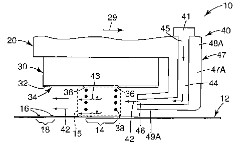
Figures 2A, 2B, and 2C illustrate one embodiment of a portion of an inkjet
printer
10 for printing on a print medium 12. Inkjet printer 10 includes a printer
carriage 20, a
print cartridge 30, and an air current disruption system 40. Print medium 12
includes a
print region 14 within which print 16 in the form of characters and graphics
is created as
relative movement between print cartridge 30 aald print medium 12 occurs
during
printing. Print medium 12 is any type of suitable material, such as paper,
cardstock,
transparencies, Mylar, and the like. In one embodiment, during printing, print
medium 12
is held stationary as printer carriage 20 moves in a printing direction, as
indicated by
arrow 29, to traverse print medium 12. Upon completing a row of print 16,
print medium
12 is advanced in a direction substantially perpendicular to the printing
direction
indicated by arrow 29 (i.e., in and out of the plane of the paper).
Printer carriage 20 is slidably supported within a chassis (not shown) of
inkjet
printer 10 for travel back and forth across print medium 12, and print
cartridge 30 is
installed in printer carriage 20 for movement with printer carriage 20 during
printing.
Print cartridge 30 includes a printhead 34 having a front face 32 in which a
plurality of
inlc orifices or nozzles 36 are formed in a manner well known to those skilled
in the art.
Example embodiments of printhead 34 include a thermal printhead, a
piezoelectric
printhead, flex-tensional printhead, or any other type of inkjet ejection
device known in
the art. If printhead 34 is, for example, a thermal printhead, printhead 34
typically
includes a substrate layer (not shown) having a plurality of resistors (not
shown) which
are operatively associated with ink orifices 36. Upon energization of the
resistors, in
CA 02409481 2002-11-08
WO 01/87619 PCT/USO1/15472
response to command signals delivered by a controller (not shown) to printer
carriage 20,
drops of inlc 38 are ejected through inlc orifices 36 toward print medium 12.
During printing, inlc drops 38 are ejected from printhead 34 toward print
region 14
of print medium 12 to create print 16. As printer carriage 20 moves in the
printing
direction indicated by arrow 29, print 16 creates an already-imprinted region
18 on print
medium 12. Ink drops 38 axe ejected through inlc orifices 36 and from
printhead 34 into a
print zone 15 with an intended ink drop trajectory. Print zone 1 S is defined
as being
between printhead 34 and print medium 12, and encompasses ink drops 38. As
such,
print zone 15, as well as print region 14 of print medium 12, move with
printer carriage
20 during printing. The intended ink drop trajectory is defined by a plurality
of ink drops
38 ejected toward print medium 12 to form a curtain of ink drops 38 extending
between
printhead 34 and print medium 12. In one embodiment, the intended ink drop
trajectory
is substantially perpendicular to print region 14 of print medium 12.
Air current disruption system 40 directs a stream of gas, for example, an air
stream 42, through print zone 15 as ink drops 38 are ejected from printhead 34
during
printing. As such, air current disruption system 40 disrupts air currents, as
illustrated at
43, acting on ink drops 38 during printing so as to prevent print defects
caused by the air
currents. Air current disruption system 40, however, does not disrupt the
intended ink
drop trajectory of ink drops 38 during printing. W one embodiment, air stream
42 is
directed substantially perpendicular to the intended ink drop trajectory and
substantially
parallel to print region 14 of print medium 12 toward which ink drops 38 are
ejected.
While the following description only refers to using air, it is understood
that use of other
gases, or combinations of gases, is within the scope of the present invention.
In one embodiment, air stream 42 is directed in a direction toward already-
imprinted region 18 of print medium 12. As illustrated in Figures 2A and 2B,
for
example, printer carriage 20 and print cartridge 30 move in the printing
direction
indicated by arrow 29, from Ieft to right, relative to print medium 12. Thus,
already-
imprinted region 18 is created to the left of printer carriage 20. Air stream
42, therefore,
is directed in a direction from right to left, toward already-imprinted region
18 or,
conversely, opposite the printing direction indicated by arrow 29. In an
alternate
embodiment, air stream 42 is directed in a direction away from already-
imprinted region
18 of print medium 12. As illustrated in Figure ZC, for example, printer
carriage 20 and
CA 02409481 2002-11-08
WO 01/87619 PCT/USO1/15472
print cartridge 30 move in the printing direction indicated by arrow 29, from
right to left,
relative to print medium 12. Thus, already-imprinted region 18 is created to
the right of
printer carriage 20. Air stream 42, therefore, is directed in a direction from
right to left,
away from already-imprinted region 18 or, conversely, with the printing
direction
indicated by arrow 29.
In one embodiment, air current disruption system 40 includes an airflow
channel
44 which directs air stream 42 through print zone 15. Airflow channel 44
includes an
inlet flow path 45 and an outlet flow path 46. Inlet flow path 45 communicates
with an
airflow source 41 which creates a pressurized source of air which, in turn,
generates and
forces air stream 42 through airflow channel 44.
In one embodiment, airflow source 41 includes a direct source which
communicates with inlet flow path 45 and forces air stream 42 through airflow
channel
44. An example of airflow source 41 is a fan positioned within inkjet printer
10. In
another embodiment, airflow source 41 includes an indirect source which
communicates
with inlet flow path 45 and forces air stream 42 through airflow channel 44.
Thus,
another example of airflow source 41 is inkjet printer 10 itself. More
specifically, air
stream 42 is generated by movement of printer carriage 20 within inkjet
printer 10.
Printer carriage 20, for example, is slidably fitted within an elongated
cavity (not shown)
of the chassis of inlcjet printer 10 such that motion of printer carriage 20
generates a high-
pressure area within a portion of the cavity on a side of printer carriage 20
preceding print
formation. As such, the portion of the cavity on the side of printer carriage
20 preceding
print formation is communicated with airflow channel 44 to create air stream
42. While
airflow source 41 is illustrated as being positioned adjacent inlet flow path
45, it is within
the scope of the present invention for airflow source 41 to be positioned
remotely from
and communicated with inlet flow path 45.
In one embodiment, as illustrated in Figures 2A, 2B, and 2C, airflow channel
44 is
formed by an airflow duct 47 provided at a side of printer carriage 20 for
travel with
printer carriage 20 during printing. While airflow duct 47 is illustrated as
being formed
integrally with printer carriage 20, it is within the scope of the present
invention for
airflow duct 47 to be formed separately from printer carriage 20. As such, it
is also
within the scope of the present invention for airflow duct 47 to move with
printer carriage
20 or be held stationary relative to printer carriage 20.
CA 02409481 2002-11-08
WO 01/87619 PCT/USO1/15472
9
Figures 2A and 2C illustrate one embodiment of airflow duct 47. Airflow duct
47A includes an inlet portion 48A forming inlet flow path 45 of airflow
channel 44 and
an outlet portion 49A forming outlet flow path 46 of airflow channel 44.
Outlet portion
49A is oriented substantially parallel to print region 14 of print medium 12
and
substantially parallel to front face 32 of printhead 34. During printing,
outlet portion 49A
is interposed between print cartridge 30 and print medium 12 such that air
stream 42 is
directed out outlet flow path 46 of airflow channel 44 and through print zone
15
substantially parallel to print region 14 and front face 32 of printhead 34.
Figure 2B illustrates another embodiment of airflow duct 47. Airflow duct 47B
includes an inlet portion 48B forming inlet flow path 45 of airflow channel 44
and an
outlet portion 49B forming outlet flow path 46 of airflow channel 44. Outlet
portion 49B
is oriented at an angle to print region 14 of print medium 12 and front face
32 of
printhead 34. Outlet portion 49B, however, does not project beyond front 32
face of print
cartridge 30, so as to permit narrow pen-to-paper spacing. During printing,
air streaan 42
is directed at an angle toward print medium 12 such that air stream 42 is
deflected by
print medium 12 and directed through print zone 15 substantially parallel to
print region
14 and front face 32 of printhead 34.
Figure 2D illustrates another embodiment of inkjet printer 10 including
printer
carxiage 20, print cartridge 30, and an air current disruption system 40'.
During printing,
print medium 12 is held stationary as printer carriage 20 moves in the
printing direction
indicated by arrow 29 to traverse print medium 12, and create print 16 and
already-
imprinted region 18. Upon completing a row of print 16, print medium 12 is
advanced in
the direction substantially perpendicular to the printing direction indicated
by arrow 29
(i.e., in and out of the plane of the paper). Thereafter, print medium 12 is
held stationary
as printer carriage 20 moves in a printing direction, as indicated by arrow
29', opposite
the printing direction indicated by arrow 29, to traverse print medium 12 and
create print
16' and already-imprinted region 18'.
Air current disruption system 40' directs air stream 42 through print zone 15
as
ink drops 3 8 are ej ected from printhead 34 during printing when printer
carriage 20
moves in the printing direction indicated by arrow 29. Air current disruption
system 40'
also directs an air stream 42' through print zone 15 as ink drops 38 are
ejected from
CA 02409481 2002-11-08
WO 01/87619 PCT/USO1/15472
I0
printhead 34 during printing when printer carriage 20 moves in the printing
direction
indicated by arrow 29'. As such, air current disruption system 40' disrupts
air currents, as
illustrated at 43 and 43', acting on ink drops 38 during printing when printer
carriage 20
moves in the printing directions indicated by arrows 29 and 29', respectively,
to prevent
print defects caused by the air currents. Air current disruption system 40',
however, does
not disrupt the intended ink drop trajectory of ink drops 38 during printing.
In one embodiment, air current disruption system 40' includes airflow channel
44
which directs air stream 42 through print zone 15 when printer carriage 20
moves in the
printing direction indicated by arrow 29 and an airflow channel 44' which
directs air
stream 42' through print zone 15 when printer caiTiage 20 moves in the
printing direction
indicated by arrow 29'. Accordingly, airflow channel 44 includes inlet flow
path 45 and
outlet flow path 46, and airflow channel 44' includes an inlet flow path 45'
and an outlet
flow path 46', wherein inlet flow path 45 cormnunicates with airflow source 41
and inlet
flow path 45' communicates with an airflow source 41' similar to airflow
source 41.
While airflow source 41' is illustrated as being separate from airflow source
41, it is
within the scope of the present invention for airflow source 41' and airflow
source 41 to
be a single airflow source.
Figures 3A and 3B illustrate another embodiment of inkjet printer IO including
printer carriage 20, print cartridge 30, and an air current disruption system
140 similar to
air current disruption system 40. Air current disruption system 140 directs an
air stream
142 through print zone 15 as ink drops 38 are ejected from printhead 34 during
printing.
As such, air current disruption system 140 disrupts air currents, as
illustrated at 143,
acting on ink drops 38 during printing to prevent print defects caused by the
air currents.
Air current disruption system 140, however, does not disrupt the intended ink
drop
trajectory of ink drops 38 during printing. In one embodiment, air stream 142
is directed
substantially perpendicular to the intended ink drop trajectory and
substantially parallel to
print region 14 of print medium 12 toward wluch inlc drops 38 are ejected.
In one embodiment, air stream 142 is directed in a direction toward already-
imprinted region 18 of print medium 12. As illustrated in Figures 3A and 3B,
for
example, printer carriage 20 and print cartridge 30 move in the printing
direction
indicated by arrow 29, from left to right, relative to print medium 12. Thus,
already-
CA 02409481 2002-11-08
WO 01/87619 PCT/USO1/15472
11
imprinted region 18 is created to the left of printer carriage 20. Air stream
142, therefore,
is directed in a direction from right to left, toward already-imprinted region
18 or,
conversely, opposite the printing direction indicated by arrow 29. It is,
however, within
the scope of the present invention for air stream 142 to be directed in a
direction away
from already-imprinted region 18 of print medium 12. When printer carriage 20
and print
cartridge 30, for example, move in a direction opposite the printing direction
indicated by
arrow 29 in Figure 3A, from right to left, relative to print medium 12,
already-imprinted
region 18 is created to the right of printer carriage 20. Air stream 142,
therefore, is
directed in a direction from right to left, away from already-imprinted region
18 or,
conversely, with the printing direction.
In one embodiment, air current disruption system 140 includes an airflow
channel
144 which directs air stream 142 through print zone 15. Airflow channel 144
includes an
inlet flow path 145 and an outlet flow path 146. While inlet flow path 45 of
air current
disruption system 40 communicates with airflow source 41 to generate air
stream 42
(Figures 2A, 2B, 2C, and 2D), outlet flow path 146 of air current disruption
system I40
communicates with an airflow source 141 which generates air stream 142 and
draws air
stream 142 through airflow channel 144 (Figures 3A and 3B). In one embodiment,
airflow source 141 includes a direct source which communicates with outlet
flow path
146 and pulls air through inlet flow path 145 to create a vacuum next to
printhead 34
which, in turn, draws air stream 142 through print zone 15 and into inlet flow
path 145.
An example of airflow source 141 is an extraction fan positioned within inkjet
printer 10.
In one embodiment, as illustrated in Figures 3A and 3B, airflow channel 144 is
formed by an airflow duct 147 provided at a side of printer carriage 20 for
travel with
printer carriage 20 during printing. While airflow duct I47 is illustrated as
being formed
integrally with printer carriage 20, it is within the scope of the present
invention for
airflow duct 147 to be formed separately from printer carriage 20. As such, it
is also
within the scope of the present invention for airflow duct 147 to move with
printer
carriage 20 or be held stationary relative to printer carriage 20.
Figure 3A illustrates one embodiment of airflow duct I47. Airflow duct I47A
includes an inlet portion 148A forming inlet flow path I45 of airflow channel
144 and an
outlet portion I49A forming outlet flow path 146 of airflow channel I44. Inlet
portion
148A is oriented substantially parallel to print region 14 of print medium 12
and
CA 02409481 2002-11-08
WO 01/87619 PCT/USO1/15472
12
substantially parallel to front face 32 of printhead 34. During printing,
inlet portion 148A
is interposed between print cartridge 30 and print mediiun 12 such that air
stream 142 is
directed through print zone 15 substantially parallel to print region 14 and
front face 32 of
printhead 34 and into inlet flow path 145 of air flow channel 144.
Figure 3B illustrates another embodiment of airflow duct 147. Airflow duct
147B
includes an inlet portion 148B forming inlet flow path 145 of airflow channel
144 and an
outlet portion 149B forming outlet flow path 146 of airflow chaimel 144. Inlet
portion
148B is oriented at an angle to print region 14 of print medium 12 acid to
front face 32 of
printhead 34. Inlet portion 148B, however, does not project beyond front face
32 of
printhead 34 so as to permit narrow pen-to-paper spacing. During printing, air
stream 142
is directed through print zone 15 substantially parallel to print region 14
and front face 32
of printhead 34 and drawn into inlet flow path 145 of air flow channel 144.
Figures 4A and 4B illustrate another embodiment of a portion of an inkjet
printer
210 for printing on a print medium 212. Inkjet printer 210 includes a printer
carriage 220,
a print cartridge 230, and an air current disruption system 240. Print medium
212
includes a print region 214 within which print 216 in the form of characters
and graphics
is created as relative movement between print cartridge 230 and print medium
212 occurs
during printing. Inlcjet printer 210 is similar to inkjet printer 10 with
exception that,
during printing, print medium 212 traverses in a direction indicated by arrow
219, which
is opposite to a printing direction, for relative movement between print
cartridge 230 and
print medium 212. During printing, print medium 212 traverses in the direction
of arrow
219 and printer carriage 220 advances in a direction substantially
perpendicular to the
direction indicated by arrow 219 (i.e., in and out of the plane of the paper).
It is also
within the scope of the present invention for print medium 212 to traverse in
a direction
opposite the direction indicated by arrow 219.
Printer carriage 220 is supported within a chassis (not shown) of inlcjet
printer 210
and print cartridge 230 is installed in printer carriage 220. Print cartridge
230 includes a
printhead 234 having a front face 232 in which a plurality of ink orifices or
nozzles 236
axe formed. Operation of printhead 234 is the same as that previously
described in
connection with printhead 34 and, therefore, is omitted here.
During printing, ink drops 238 are ejected from printhead 234 toward print
region
214 of print medium 212 to create print 216. As print medium 212 moves in the
direction
CA 02409481 2002-11-08
WO 01/87619 PCT/USO1/15472
13
indicated by arrow 219, print 216 creates an already-imprinted region 218 of
print
medium 212. Ink drops 238 axe ejected through inlc orifices 236 and from
printhead 234
into a print zone 215 with an intended ink drop trajectory. Print zone 215 is
defined
between printhead 234 and print medium 212, and encompasses ink drops 238.
Air current disruption system 240 for inkjet printer 210 is similar to air
current
disruption system 40 for inkjet printer 10. Air current disruption system 240
directs an air
stream 242 through print zone 215 as ink drops 238 are ejected from printhead
234 during
printing. As such, air current disruption system 240 disrupts air currents, as
illustrated at
243, acting on ink drops 238 during printing to prevent print defects caused
by the air
currents. Air current disruption system 240, however, does not disrupt the
intended inlc
drop trajectory of ink drops 238 during printing. In one embodiment, air
stream 242 is
directed substantially perpendicular to the intended ink drop trajectory and
substantially
parallel to print region 214 of print medium 212 toward which ink drops 238
are ejected.
In one embodiment, air stream 242 is directed in a direction toward already-
imprinted region 218 of print medium 212. As illustrated in Figures 4A and 4B,
for
example, print medium 212 moves in the direction indicated by arrow 219, from
right to
left, relative to print cartridge 230. Thus, already-imprinted region 218 is
created to the
left of printer carriage 220. Air stream 242, therefore, is directed in a
direction from right
to left, toward already-imprinted region 218 or, conversely, opposite the
printing
direction. It is, however, within the scope of the present invention for air
stream 242 to
be directed in a direction away from already-imprinted region 218 of print
medium 212.
When print medium 212, for example, moves in a direction opposite the
direction
indicated by arrow 219 in Figure 4A, from left to right, relative to printer
carriage 220
and print cartridge 230, already-imprinted region 218 is created to the right
of printer
caxriage 220. Air stream 242, therefore, is directed in a direction from right
to left, away
from already-imprinted region 218 or, conversely, with the printing direction.
In one embodiment, air current disruption system 240 includes an airflow
channel
244 which directs air stream 242 through print zone 215. Airflow channel 244
includes
an inlet flow path 245 and an outlet flow path 246. Inlet flow path 245
communicates
with an airflow source 241 which creates a pressurized source of air which, in
turn,
generates and forces air stream 242 through airflow channel 244. In one
embodiment,
airflow source 241 includes a direct source which communicates with inlet flow
path 245
CA 02409481 2002-11-08
WO 01/87619 PCT/USO1/15472
14
and forces air stream 242 through airflow channel 244. An example of airflow
source
241 is a fan positioned within inlcjet printer 210.
In one embodiment, as illustrated in Figures 4A and 4B, airflow channel 244 is
formed by an airflow duct 247. Airflow duct 247 is provided at a side of
printer carriage
220 preceding print formation. Figure 4A illustrates one embodiment of airflow
duct 247
and Figure 4B illustrates another embodiment of airflow duct 247. Airflow duct
247A is
similar to airflow duct 47A and airflow duct 247B is similar to airflow duct
47B. As
such, airflow duct 247A includes an inlet portion 248A forming inlet flow path
245 of
airflow channel 244 and an outlet portion 249A forming outlet flow path 246 of
airflow
channel 244 and, airflow duct 247B includes an inlet portion 248B forming
inlet flow
path 245 of airflow channel 244 and an outlet portion 249B forming outlet flow
path 246
of airflow channel 244.
Figure 5 illustrates another embodiment of inkjet printer 10 including printer
carriage 20, print cartridge 30, and an air current disruption system 40".
During printing,
printer carriage 20 moves in the printing direction indicated by arrow 29" and
air current
disruption system 40" directs air stream 42 through print zone 15 as ink drops
3 8 are
ejected from printhead 34. As such, air current disruption system 40" disrupts
air
currents, as illustrated at 43, acting on ink drops 38 during printing. Air
current
disruption system 40", however, does not disrupt the intended ink drop
trajectory of ink
drops 38 during printing. In one embodiment, air stream 42 is directed
substantially
parallel to the intended ink drop trajectory and substantially parallel to
front face 32 of
printhead 34.
In one embodiment, air current disruption system 40" directs a patterned or
pinpoint air stream through print zone 15. As such, an outlet portion 49 of
airflow duct
47 includes a plurality or an array of outlet flow paths 46 which direct air
stream 42
through print zone 15. Outlet flow paths 46, for example, are offset from a
column of ink
orifices 36 and direct air stream 42 between and/or along columns of inlc
orifices 36.
While printhead 34 is illustrated as having two columns of ink orifices 36, it
is within the
scope of the present invention for one or more colurmls of ink orifices 36 or
an array of
ink orifices 36 to be formed in front face 32 of printhead 34.
CA 02409481 2002-11-08
WO 01/87619 PCT/USO1/15472
In use, air current disruption system 40,40',40", for example, directs air
stream 42
through print zone 15 as inlc drops 38 are ejected from printhead 34 during
printing. Air
stream 42 is directed substantially parallel to print region 14 of print
medium 12 and front
face 32 of printhead 34. In one embodiment, air stream 42 is directed in a
direction
5 toward already-imprinted region 18 of print medium 12 or, conversely, in a
direction
opposite the printing direction indicated by arrow 29,29'. In an alternate
embodiment, air
stream 42 is directed in a direction away from already-imprinted region I 8 of
print
medium I2. In one embodiment, air stream 42,42' is directed in a direction
substantially
parallel to the printing direction indicated by arrow 29,29' (i.e., with the
plane of the
10 paper) and substantially perpendicular to the intended ink drop trajectory.
In an alternate
embodiment, air stream 42 is directed in a direction substantially
perpendicular to the
printing direction indicated by arrow 29" and substantially parallel to the
intended ink
drop trajectory. While air stream 42 is illustrated as being directed
substantially
perpendicular and substantially parallel to the intended ink drop trajectory,
it is also
15 within the scope of the present invention for air stream 42 to be directed
at any angle
between substantially perpendicular and substantially parallel. Thus, it is
within the
scope of the present invention for air stream 42 to be directed at an angle to
the intended
inlc drop trajectory and an axis of motion of printer carriage 20.
A speed of air stream 42 is selected so as to disrupt air currents acting on
ink
drops 38 during printing, but not disrupt the intended ink drop trajectory
during printing.
In one illustrative embodiment, the speed of air stream 42 through print zone
15 is in a
range of approximately 0.5 meters/second to approximately 2.0 meters/second.
In
another illustrative embodiment, the speed of air stream 42 is limited to a
range of
approximately 1.0 meters/second to approximately 1.5 meters/second. In another
illustrative embodiment, the speed of air stream 42 is approximately 1.0
meters/second.
In addition, a relative speed between printer carriage 20 and print medium 12
is
approximately 0.5 meters/second or higher, and a pen-to-paper spacing between
print
cal-tridge 30 and print medium 12 is approximately 1 millimeter or more. In
addition, a
firing frequency of print cartridge 30 is approximately 12 kilohertz or
higher, and a
spacing of ink orifices 36 of printhead 34 is approximately 84 micrometers or
less.
Furthermore, a drop volume of each of ink drops 38 is approximately 10
picoliters or less,
and a drop velocity of each of ink drops 38 is approximately 5 meters/second
or greater.
CA 02409481 2002-11-08
WO 01/87619 PCT/USO1/15472
16
Figures 6 and 7 illustrate enlarged image portions printed by an inlcjet
printer
without and with, respectively, an air current disruption system according to
the present
invention. Figure 6 illustrates an enlarged image portion 50 printed without
an air current
disruption system according to the present invention. As illustrated in Figure
6, enlarged
image portion 50 includes print defects 51 which are identifiable by dark
lines or patches
in areas of uniform gray. Print defects 51, commonly referred to as "worms,"
produce a
patterned or mottled appearance and, as such, degrade image quality. Figure 7
illustrates
an enlarged image portion 52 printed with an air current disruption system
according to
the present invention. As illustrated in Figure 7, enlarged image portion 52
does not
include print defects 51 identifiable in Figure 6. Thus, image quality is
enhanced with the
air current disruption system according to the present invention.
By directing air stream 42 through the print zone 15 as ink drops 38 are
ejected
during printing, air current disruption system 40 disrupts air currents acting
on ink drops
38 during printing, but does not disrupt the intended trajectory of ink drops
38 during
printing. As such, undesirable print defects 51, such as "worms," are avoided
without
compromising image resolution, printing speed, and/or accommodation of various
thickness of print medium.
Although specific embodiments have been illustrated and described herein for
purposes of description of the preferred embodiment, it will be appreciated by
those of
ordinary skill in the art that a wide variety of alternate and/or equivalent
implementations
calculated to achieve the same purposes may be substituted for the specific
embodiments
shov~m and described without departing from the scope of the present
invention. Those
with skill in the chemical, mechanical, electro-mechanical, electrical, and
computer arts
will readily appreciate that the present invention may be implemented in a
very wide
variety of embodiments. This application is intended to cover any adaptations
or
variations of the preferred embodiments discussed herein. Therefore, it is
manifestly
intended that this invention be limited only by the claims and the equivalents
thereof.