Note : Les descriptions sont présentées dans la langue officielle dans laquelle elles ont été soumises.
CA 02411105 2002-12-05
WO 01/98642 PCT/USO1/41053
ENGINE OVER TEMPERATURE PROTECTION
TECHNICAL FIELD
The present invention is related to the field of over temperature
protection for internal combustion engines.
BACKGROUND ART
Most, if not all vehicles in production today utilize one or more
microprocessors and other digital electronics to control the vehicle's engine,
transmission, brakes, and a variety of other major systems. The
microprocessors and
' other electronics are typically located in one or more housings commonly
called
electronic control modules (ECM). ECMs are versatile components that can
change
their behavior and the behavior of the items they are controlling by changing
software programs executed by the ECMs. Programmability allows a single ECM
design to be adapted to many different types of engines, or transmissions, or
braking
systems, and so on. Variations in programming allow two otherwise identical
systems to exhibit different behavior. For example, two identical engines may
have
different torque ratings at a given engine RPM due to differences in
calibration tables
programmed into the ECMs.
Engine protection is an important function often programmed into
ECMs. Of particular interest are over temperature conditions during which the
engine temperature reaches levels that could be damaging or destructive. Here,
the
ECM must take some action to increase the cooling rate for the engine and/or
decrease the rate at which the engine generates heat. Problems can arise when
an
increase in the cooling rate takes a considerable time to be effective. The
engine
temperature may exceed a critical level before the additional cooling can
bring the
temperature down. On the other hand, decreasing the heat generation rate of
the
engine may be performed quickly, but it may be contrary to the wishes of the
vehicle's operator.
CA 02411105 2002-12-05
WO 01/98642 PCT/USO1/41053
One method of engine over temperature protection is disclosed U.S.
Patent No. 5,070,832 issued to Hapka et al. on December 10, 1991. Hapka et al.
discloses a method that monitors several fluid parameters associated with the
engine
looking for fault conditions. Typical faults include high fluid temperatures,
low fluid
levels and low fluid pressures. When fluid parameter faults are detected, an
ECM
derates the torque and/or speed of the engine based upon the severity and type
of
faults detected. Performance derating increases linearly as the fluid
parameters move
farther out of their normal operating ranges. Filtering provides isolation
from short
fault transients in the fluid parameters that are not sever enough to require
engine
protection. The Hapka et al. approach is most effective when the engine is
operating
neax or at its rated performance. Here, a slight derating will most likely
require the
ECM to lower the engine's actual performance. Performance derating
effectiveness
drops in scenarios where the engine is operating well below its ratings. In
these
cases, the derated performance may still be above the engine's actual
performance
and thus the ECM is not required to change engines' operations.
Another engine over protection approach is to reduce the torque
controlling signal or signals being used to control the engine. In this
approach, the
ECM records the values of the torque controlling signals at the beginning of
an over
temperature condition. These signals are then reduced as a linear function of
temperature to cause the torque and heat being generated by the engine to
reduce.
In this approach, the ECM will always take some action that will promote the
lowering of the engine's temperature.
A consequence of both engine protection approaches is that the
vehicle's driver may become aware of the protective action due to a reduction
in the
vehicle's speed and/or the illumination of a notification lamp. When this
happens,
the driver may attempt to compensate by increasing the throttle input
manually. This
usually does not have the desired effect since the ECM is executing the engine
protection routine. As a result, the driver typically concludes that the
engine has
somehow failed. While an engine failure is one possible explanation for the
over
temperature condition, another explanation is that the engine is being
operated
outside its designed operating environment. For example, an engine over
-2-
CA 02411105 2002-12-05
WO 01/98642 PCT/USO1/41053
temperature condition may be caused by the vehicle moving up a steep grade
high
in the mountains carrying a heavy load on an unusually hot day. In this
example,
there may not be sufficient air flow past the radiator to cool the engine
adequately.
DISCLOSURE OF INVENTION
The present invention is method of operation to protect an engine
during an over temperature condition, an information recording medium
including
a computer program implementing the method, and an electronic control module
performing the method. Onset of the protection is made gradual to minimize the
impact of the protection on overall engine performance. The rate of protection
then
increases if the engine temperature continues to increase.
An operating torque signal representative of a torque being generated
by the engine is recorded to produce a recorded torque value in response to a
temperature signal representative of a temperature of the engine exceeding a
protection temperature threshold. The torque being generated by the engine is
then
reduced as a nonlinear function of the temperature signal and the recorded
torque
value to promote lowering of the temperature of the engine. A notification
indicator
and a warning indicator are activated if the engine temperature exceeds a
notification
temperature threshold and a warning temperature threshold respectively. The
torque
reduction may be limited to no less than a fixed percentage of the recorded
torque
value, or to no less than a minimum absolute torque value, whichever is
greater.
Diagnostic fault logging may be provided to log the engine temperature
exceeding the protection, notification and warning temperature thresholds.
Fault
broadcasting may also be provided to notify other control modules and systems
that
the engine temperature has exceeded the notification and then the warning
temperature thresholds.
Accordingly, it is an object of the present invention to provide a
method and apparatus for protecting and engine during an over temperature
condition
implementing a nonlinear response to the engine temperature.
-3-
CA 02411105 2002-12-05
WO 01/98642 PCT/USO1/41053
These and other objects, features and advantages will be readily
apparent upon consideration of the following detailed description in
conjunction with
the accompanying drawings.
BRIEF DESCRIPTION OF DRAWINGS
Figure 1 is a component block diagram of an electronic control
module;
Figure 2 is a functional flow diagram showing the electronic control
module implementing over temperature protection;
Figure 3 is a graph of an operating torque signal reduced as a function
of temperature during the over temperature condition;
Figure 4 is a graph of an operating torque signal reduced as a second
function of temperature and limited at a minimum torque value; and
Figure 5 is a graph of the operating torque signal reduced as a third
function of temperature.
BEST MODE FOR CARRYING OUT THE INVENTION
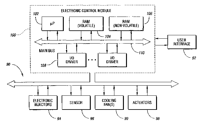
Figure 1 shows an electronic. control module (ECM) 100 in
communication with typical engine componentry, shown generally be reference
numeral 90, and a user-interface 92. As shown, the ECM 100 includes a
microprocessor 102 having volatile random access memory (RAM) 104 and
nonvolatile read-only memory (ROM) 106. Of course, the ECM may contain other
types of memory instead of, or in addition to RAM 104 and ROM 106, such as
flash
EPROM and EEPROM memories, as is well known in the art.
-4-
CA 02411105 2002-12-05
WO 01/98642 PCT/USO1/41053
The ROM 106, or other nonvolatile memory, may contain instructions
that are executed to perform various control and information functions, and
data
tables that contain calibration values and parameters characterizing normal
engine
operation. Microprocessor 102 imparts control signals to, and receives signals
from
input and output (I/O) drivers 108. The I/O drivers 108 are in communication
with
the engine componentry 90 and serve to protect the ECM 100 from hostile
electrical
impulses while providing the signals and power necessary for engine control
according to the present invention. The ECM 100 componentry detailed above is
interconnected by data, address and control busses 110. It should be noted
that there
are a variety of other possible control schemes that include various
combinations of
microprocessors and electric and electronic circuits that could perform the
same
functions.
Engine componentry 90 includes a plurality of electronic unit injectors
(EUI) 94, each associated with a particular engine cylinder (not shown); and a
plurality of sensor 96 for indicating various engine operating conditions.
Examples
of these conditions include, but are not limited to coolant temperature,
ambient air
temperature, intake manifold air temperature, inlet air temperature, engine
oil
temperature, fuel temperature, intercooler temperature, throttle position,
intake
manifold pressure, fuel pressure, oil pressure, coolant pressure, cylinder
position,
and cylinder sequencing. Engine componentry 90 also includes actuators 98 that
may
include solenoids, variable valves, indicator lights, motors and generators.
It should
be appreciated that the ECM 100 may also be in communication with other
vehicle
componentry 90, such as cooling fans 99, and other microprocessors (not shown)
that
control associated vehicle systems such as brakes, transmission, a vehicle
management system and a fleet management radio transponder.
User-interface 92, also known as a data hub, is used to store user-
selected monitoring parameters and associated values fox those parameters, to
determine service intervals and to perform trend analysis. The user selected
parameters may include adjustable limits, such as desired engine oil life.
Engine
historical information may include diagnostic information used to assist
personnel
performing routine maintenance or troubleshoot malfunctions, as well as engine
and
-5-
CA 02411105 2002-12-05
WO 01/98642 PCT/USO1/41053
vehicle operation data that may be analyzed to evaluate vehicle operator
performance
in addition to vehicle performance. It should be appreciated that although
Figure 1
illustrates the user-interface as external to the ECM 100, certain operations
performed by the user-interface 92 could also be performed by the ECM 100.
A functional block diagram showing the electronic control module
implementing over temperature protection is shown in Figure 2. A driver's
throttle
position signal is entered by the driver through a throttle position sensor,
as shown
in block 200. The throttle input signal is then filtered, as shown in block
202, to
produce a requested torque signal. Initial control functions are applied to
the
requested torque signal, as shown in block 204, to produce an intermediate
torque
signal. One example of an initial control function is a torque governing
function that
restricts the requested torque signal between minimum and maximum torque
limits.
The governing function prevents the engine from stalling at low speeds and
from
damaging itself or other systems at high torque loads. Another example of an
initial
control function is an emissions control function. Here, the requested torque
signal
is controlled to limit emissions produced by the engine as the engine is
warning up.
It will be understood by those skilled in the art that other types of initial
control
functions may be implemented within the scope of the present invention.
In block 206, the intermediate torque signal is comparted with a
protection torque signal and the smaller of the two signals is output as a
final torque
signal. The protection torque signal is generated by the ECM as part of the
over
temperature protection function 208 of the present invention and will be
discussed in
detail below. The final toque signal is input into final control functions, as
shown in
block 210, to produce various signals applied to the engine. Examples of final
control functions include, but are not limited to fuel temperature
compensation,
air/fuel ratio control, and electronic unit injector control. These control
functions
determine the amount of air and fuel to be entered into the engine, spark
generation
(if applicable), actuator energization, and associated timing to control
actual operation
of the engine, an in particular the torque generated by the engine.
-6-
CA 02411105 2002-12-05
WO 01/98642 PCT/USO1/41053
The engine functions to convert air and fuel into rotational motion
having a rotational speed and torque, as shown in block 212. Any type of
internal
combustion engine may be used within the scope of the present invention. For
example, the engine may operate on a four-stroke or a two-stroke cycle,
utilize spark
gap or diesel ignition of the air/fuel mixture, operate at a variable or fixed
speed, and
operate at a variable or fixed loading. A transmission functions to convert
the
rotational motion received from the engine into useful ranges of rotational
speed and
torque as required by the particular application, as shown in block 214. In
the case
of a vehicle, an output of the transmission is applied to wheels to convert
the
rotational motion into linear movement of the vehicle, as shown in block 216.
It will
be appreciated that in other applications the wheels may be another type of
load such
as an electrical generator, a pump, or the like.
A cruise control function, as shown by block 218, may be included to
provide feedback for automated speed control. Input to the cruise control
function
may be either the engine speed as determined from an output drive shaft of the
engine, or a vehicle speed as determined from the wheel speed. The cruise
control
function operates to convert the measured speed into a second requested torque
signal. The second requested torque signal is then compared with the requested
torque signal output from the filter function, and the larger of the two
signals is
provided to the initial control functions, as shown in block 220.
An engine over temperature condition is detected by the ECM 100
based upon information received from the sensors 96. The sensors 96 measure
various parameters associated with the engine, as shown in block 222. In the
preferred embodiment, the sensors 96 measure a coolant level, a coolant
temperature,
an oil pressure and an oil temperature. Additional parameters that could be
monitored include, but are not limited to, a coolant pressure, a crankcase
pressure,
an intercooler temperature, an intercooler pressure and various auxiliary
inputs.
Signals from the sensor 96 are provided to the ECM 100 where a temperature of
the
engine is determined. A diagnostic function, block 224, uses this information
to
determine if and when over temperature protection of the engine is required,
as
CA 02411105 2002-12-05
WO 01/98642 PCT/USO1/41053
shown in block 224. Output from the diagnostic function includes a temperature
signal that represents the engine's temperature.
The protection torque signal is generated by the engine over
temperature function, as shown in block 208, when the diagnostic function
determines that over temperature protection for the engine is required. In the
preferred embodiment, the protection torque signal is a percentage of the
intermediate
torque signal sampled at the moment in time that the over temperature
condition
begins. As described above, the protection torque signal is compared with the
intermediate torque signal in block 206 and the smaller of the two signals is
used as
the final torque signal. In this way, the driver cannot command the engine to
produce
a higher torque, possibly resulting in a higher engine temperature. On the
other
hand, the driver may enter a requested torque lower than the protection
torque.
Here, the driver's lower requested torque will be accepted and used for the
final
torque signal, resulting in a lower engine temperature.
The engine over temperature function records the intermediate torque
signal as a recorded torque value when the engine temperature exceeds a
protection
temperature threshold. Here, the intermediate torque signal is treated an
operating
torque signal representative of the torque being generated by the engine. It
should
be noted that other signals available to the ECM 100 may be used as the
operating
torque signal. For example, the operating torque signal may be sampled prior
to the
initial control functions 204. In this example, the minimum selection function
of
block 206 would take place prior to the initial control function 204, and
would select
the smaller of the requested torque signal and the protection torque signal.
Likewise,
the sampling of the operating torque signal make take place at some
intermediate
point within the final control functions 210. In still another example, if the
cruise
control function 218 is utilized at all times, then the operating torque
signal may be
sampled from within the cruise control function 218, or from the second
requested
torque signal at the output of the cruise control function 218. Those skilled
in the art
will appreciate that the exact location or locations where the operating
torque signal
is recorded from may be varied in different control schemes within the scope
of the
present invention.
_g_
CA 02411105 2002-12-05
WO 01/98642 PCT/USO1/41053
As the temperature signal increases above the protection temperature
threshold, then the protection torque signal is reduced as a nonlinear
function of the
temperature signal and the recorded torque value. Different nonlinear
functions of
the protection torque signal 300 are graphed as a function of the temperature
signal
302 in Figures 3, 4 and 5. Referring to Figure 3, over temperature protection
begins
when the temperature signal 302 exceeds a protection temperature threshold
304.
Above the protection temperature threshold 304, the protection torque signal
300 is
slightly less than 100% of the recorded torque value (shown at point 305.) As
the
temperature signal 302 increases, the protection torque signal 300 is reduced
in a
nonlinear fashion. The initial rate of reducing the protection torque signal
is
designed to be slow at the onset of reduction. This is done to minimize the
impact
of the engine torque reduction on the vehicle while still encouraging an
engine
temperature reduction. Another benefit of a gradual initial reduction rate is
that there
is no need to filter transients in the temperature signal. A momentary rise in
the
engine temperature, or noise in one of the sensor signals can trigger over
temperature
protection without having a major impact of overall engine performance. There
is
no filtering delay to the start of the over temperature protection.
If the initial over temperature protection does not lower the engine
temperature, then the rate of protection torque signal reduction is increased
as the
temperature signal 302 increases to promote even greater cooling of the
engine.
When the temperature signal 302 exceeds a notification temperature threshold
306,
then the ECM 100 notifies the driver that the over temperature protection is
already
in progress. Returning to Figure 2, notification is performed by activating a
notification indicator visible to the driver, as shown in block 226. This
notification
indicator is commonly known as a "Check Engine Lamp". Notification may also be
in the form of an audio signal, such as a tone or voice message.
Referring again to Figure 3, protection torque signal reduction
continues if the temperature signal 302 continues to increase above the
notification
temperature threshold. When the temperature signal 302 exceeds a warning
temperature threshold 308, then the ECM activates a warning to the driver. As
with
the notification, the warning is typically in the form of a lamp, commonly
called a
-9-
CA 02411105 2002-12-05
WO 01/98642 PCT/USO1/41053
"Stop Engine Lamp" . Illumination of this lamp informs the driver that some
action
must be taken to avoid damage of destruction of the engine. A choice of manual
action, automatic action or a combination of both may be incorporated within
the
present invention. The meaningful event is that the over temperature
protection
function may not take any additional action above the warning temperature
threshold
308. In the preferred embodiment, protection torque signal reduction is
limited at a
fixed percentage 310 of the recorded torque value. This approach allows the
engine
to continue to rotate while decisions are made elsewhere to stop the engine or
continue operation at the probable cost of engine damage or destruction.
Figure 4 shows another nonlinear curve of the protection torque signal
300 as a function of temperature signal 302. In this curve, the rate of
protection
torque signal reduction is a constant at temperatures between the notification
temperature threshold and the warning temperature threshold. This curve also
illustrates a condition where the operating torque was relatively low when the
over
temperature condition began. In this example, if the protection torque signal
300
were allowed to follow its calibration curve, then the torque being generated
by the
engine would fall below a minimum torque level, as shown by the phantom
portion
400 of the curve. Instead, the ECM 100 may be programmed to limit the
protection
torque signal 300 to no less than a minimum value 402 that corresponds to the
minimum absolute torque that the engine should produce to maintain rotation.
Note
that this limiting may take place while the temperature signal 302 is below
the
warning temperature threshold 308 (as shown) or even below the notification
temperature threshold 306.
Figure 5 shows yet another nonlinear curve where the protection
torque signal rate of reduction continues to increase as a function of the
temperature
signal 302. This curve represents applications in which engine over
temperature
protection is very important so an ever-increasing cooling is applied as the
engine
temperature gets hotter and hotter. In an extreme case, this approach would be
allowed to stall the engine to avoid damage.
-10-
CA 02411105 2002-12-05
WO 01/98642 PCT/USO1/41053
In practice, the protection torque signal curve is programmed into the
ECM 100 through the user interface 92 as a series of discrete calibration
points. The
ECM 100 interpolates between these discrete points to determine the protection
torque signal at intermediate engine temperatures. Table 1 is an example of
discrete
points used in implementing the present invention in the preferred embodiment.
Table 1
Torque Reduction Calibration Points
Engine TemperatureTorque Reduction
(F) (Percent)
212 99
214 98
216 92
218 82
220 72
222 62
224 58
226 52
228 46
In the preferred embodiment, the notification temperature threshold is
approximately
221 °F and the warning temperature threshold is approximately 227
°F.
As mentioned earlier, the ECM 100 is able to log and report diagnostic
information. An over temperature condition includes several important events
that
may be logged and reported. The first event that may be logfed is the
triggering of
the over temperature function above the protection temperature threshold 304.
Although the onset of over temperature protection may be gradual, and the
driver
may not be informed of minor over temperature conditions, the event should
still be
logged to provides historical data to maintenance personnel looking for trends
in
engine performance.
-11-
CA 02411105 2002-12-05
WO 01/98642 PCT/USO1/41053
Temperature signal 302 exceeding the notification temperature
threshold 306 is another event that should be logged. In this case, the driver
is aware
that the over temperature protection function has been invoked because the
notification indicator has been activated. An electronic record of the event
should be
recorded to support the driver's witnessing of the active notification
indicator. If the
ECM 100 is in communications with other control modules within the vehicle,
this
notification temperature threshold 306 event may also be broadcast to the
other
control modules for their use and benefit. For example, in a commercial truck
application, an automatic status report generator may use knowledge of the
notification temperature threshold 306 event to automatically update and
transmit a
vehicle health status report via a radio installed in the truck. This report
informs the
trucking company management that this particular vehicle is experiencing
problems
and should be schedule for maintenance in the near future.
A third event that should be logged is the engine temperature
exceeding the warning temperature threshold 30g. In this scenario, it is
possible that
the engine has sustained some damage and should be inspected as soon as
possible.
The ECM 100 should also broadcast this event to other control modules and
systems
that can take action based upon this information. For example, in a military
vehicle
application where the engine is allowed to overheat to the point of self
destruction,
an intelligent electrical power control system may use this information to
switch off
non-essential equipment to reduce alternator loading on the engine.
While embodiments of the invention have been illustrated and
described, it is not intended that these embodiments illustrate and describe
all
possible forms of the invention. Rather, the words used in the specification
are
words of description rather than limitation, and it is understood that various
changes
may be made without departing from the spirit and scope of the invention.
-12-