Sélection de la langue

Search

Sommaire du brevet 2411610 

Énoncé de désistement de responsabilité concernant l'information provenant de tiers

Une partie des informations de ce site Web a été fournie par des sources externes. Le gouvernement du Canada n'assume aucune responsabilité concernant la précision, l'actualité ou la fiabilité des informations fournies par les sources externes. Les utilisateurs qui désirent employer cette information devraient consulter directement la source des informations. Le contenu fourni par les sources externes n'est pas assujetti aux exigences sur les langues officielles, la protection des renseignements personnels et l'accessibilité.

Disponibilité de l'Abrégé et des Revendications

L'apparition de différences dans le texte et l'image des Revendications et de l'Abrégé dépend du moment auquel le document est publié. Les textes des Revendications et de l'Abrégé sont affichés :

  • lorsque la demande peut être examinée par le public;
  • lorsque le brevet est émis (délivrance).
(12) Demande de brevet: (11) CA 2411610
(54) Titre français: METHODE DE PRESENTATION DE PRODUITS LONGS
(54) Titre anglais: DISPLAY METHOD FOR ELONGATE PRODUCTS
Statut: Réputée abandonnée et au-delà du délai pour le rétablissement - en attente de la réponse à l’avis de communication rejetée
Données bibliographiques
(51) Classification internationale des brevets (CIB):
  • G09F 05/00 (2006.01)
  • A47F 03/14 (2006.01)
(72) Inventeurs :
  • LANGTRY, DAVID (Canada)
(73) Titulaires :
  • PATENT APPLIED TECHNOLOGY
(71) Demandeurs :
  • PATENT APPLIED TECHNOLOGY (Canada)
(74) Agent: BATTISON WILLIAMS DUPUIS
(74) Co-agent:
(45) Délivré:
(22) Date de dépôt: 2002-11-12
(41) Mise à la disponibilité du public: 2003-05-16
Licence disponible: S.O.
Cédé au domaine public: S.O.
(25) Langue des documents déposés: Anglais

Traité de coopération en matière de brevets (PCT): Non

(30) Données de priorité de la demande:
Numéro de la demande Pays / territoire Date
60/331,460 (Etats-Unis d'Amérique) 2001-11-16

Abrégés

Abrégé anglais


Elongate articles such as threaded rod and dowels are displayed for
sale in a retail situation by inserting them standing generally vertically in
a display
device having formed from a molded plastics container where a bottom portion
forms
a base member molded integrally from a plastics material and lid forms a
support
grid member also molded from a plastics material and arranged to span the side
walls. The bottom wall of the base member has upstanding walls for locating
bottom
ends of the articles. The lid has various openings across it through which the
articles extend. The lid is supplemented by small containers at spaced
positions
therearound and a post each for receiving and displaying related articles. The
lids
and bases can be stored and shipped in nested condition and erected simply by
snapping the lid onto the base.

Revendications

Note : Les revendications sont présentées dans la langue officielle dans laquelle elles ont été soumises.


-11-
CLAIMS:
1. A method for displaying for sale elongate products comprising:
providing a display device having:
a base member molded integrally from a plastics material and
having a bottom wall and side walls extending upwardly from the base member;
and a support grid member molded from a plastics material and
arranged to span the side walls at a location spaced above the base member,
the
support grid defining a plurality of openings therein;
securing the support grid at a fixed spacing above the base member;
and supporting the elongate products in an upright orientation on the
base member so as to extend through respective openings in the support grid.
2. The method according to Claim 1 including providing a plurality
of divider members protruding upwardly from the base member and supporting the
elongate products on the base member between respective divider members.
3. The method according to Claim 1 or 2 including molding the
divider members integrally with the base member.
4. The method according to Claim 1,2 or 3 wherein the side walls
enclose all sides of the base member to forma a hollow interior.
5. The method according to any one of Claims 1 to 4 including
forming the support grid separately from the base member and securing the
support
grid to the side walls.
6. The method according to any one of Claims 1 to 5 wherein the
support grid and the side walls include respective mating molded snap
fastening
means for selectively securing the support grid to the side walls.
7. The method according to any one of Claims 1 to 6 including
forming the base member and the support grid member separately and including

-12-
nesting a plurality of the base members together during storage a
transportation
thereof.
8. The method according to any one of Claims 1 to 7 including
forming the support grid member from a substantially rigid panel of plastic
material.
9. The method according to Claim 8 including forming ribs
spanning the support grid for added structural support to the support grid.
10. The method according to Claim 9 wherein the openings in the
support grid comprise apertures formed in the panel have different diameters.
11. The method according to any one of Claims 1 to 10 including
forming ribs spanning at least one of the side walls for added structural
support to
the side walls.
12. The method according to any one of Claims 1 to 11 including
providing at least one container having an open top side arranged to be
secured to
the display device and displaying associated items within said at least one
container
which are arranged co-operate with the elongate products.
13. The method according to Claim 12 wherein the containers are
mounted at spaced positions around the support grid member.
14. The method according to any one of Claims 1 to 13 including
forming the display device from a molded plastic container in which the base
member comprises a floor and respective walls of the container and the support
grid
member comprises a mating lid of the container having apertures formed therein
which define the openings in the support grid.
15. The method according to Claim 14 wherein the base member
and the lid are connected by molded snap fastening ribs surrounding the base
member and the lid respectively.
16. The method according to any one of Claims 1 to 15 including

-13-
providing an upstanding post on the base member for storing associated items.
17. Apparatus for displaying elongate products comprising:
a base member molded integrally from a plastics material and having a
bottom wall and side walls extending upwardly from the base member;
and a support grid member molded from a plastics material and
arranged to span the side walls at a location spaced above the base member,
the
support grid defining a plurality of openings therein;
wherein the support grid member is supported at a fixed spacing above
the base member;
such that the elongate products can be stored in an upright orientation
on the base member so as to extend through respective openings in the support
grid.
18. The apparatus according to Claim 17 including a plurality of
divider members protruding upwardly from the base member and supporting the
elongate products on the base member between respective divider members.
19. The method according to Claim 17 or 18 including the divider
members integral with the base member.
20. The method according to Claim 17, 18 or 19 wherein the side
walls enclose all sides of the base member to form a hollow interior.
21. The apparatus according to any one of Claims 17 to 20 wherein
the support grid is formed separately from the base member and secured to the
side
walls.
22. The apparatus according to any one of Claims 17 to 21 wherein
the support grid and the side walls include respective mating molded snap
fastening
means for selectively securing the support grid to the side walls.
23. The apparatus according to any one of Claims 17 to 22 wherein

-14-
the base member and the support grid member are formed separately and nestable
during storage and transportation thereof.
24. The apparatus according to any one of Claims 17 to 23 wherein
the support grid member is formed from a substantially rigid panel of plastic
material.
25. The apparatus according to Claim 24 including ribs spanning
the support grid for added structural support to the support grid.
26. The apparatus according to Claim 25 wherein the openings in
the support grid comprise apertures formed in the panel have different
diameters.
27. The apparatus according to any one of Claims 17 to 26
including ribs spanning at least one of the side walls for added structural
support to
the side walls.
28. The apparatus according to any one of Claims 17 to 27
including at least one container having an open top side arranged to be
secured to
the display device and displaying associated items within said at least one
container
which are arranged co-operate with the elongate products.
29. The apparatus according to Claim 28 wherein the containers are
mounted at spaced positions around the support grid member.
30. The apparatus according to any one of Claims 17 to 20 wherein
the display device is formed from a molded plastic container in which the base
member comprises a floor and respective walls of the container and the support
grid
member comprises a mating lid of the container having apertures formed therein
which define the openings in the support grid.
31. The apparatus according to Claim 30 wherein the base
member and the lid are connected by molded snap fastening ribs surrounding the
base member and the lid respectively.
32. The apparatus according to any one of Claims 17 to 31

-15-
including an upstanding post on the base member for storing associated items.

Description

Note : Les descriptions sont présentées dans la langue officielle dans laquelle elles ont été soumises.

CA 02411610 2002-11-12
DISPLAY METHOD FOR ELONGATE PRODUCTS
FIELD OF THE INVENTION
The present invention relates to a method of displaying elongate
products and more particularly to a display device therefor.
BACKGROUND
Display devices are known for displaying various products. Known
display devices for elongate products such as threaded rod, dowels and the
like in a
retail situation generally comprise a welded frame structure including an
upper grid
and a lower grid. This arrangement holds the elongate objects generally
upright for
viewing by the purchasing public in a manner where they can readily
distinguish
between products and can readily withdraw a selected product of products from
the
display rack. Re-loading by a retail clerk is also readily achieved. The use
of the
conventional metallic structures is however costly and involves numerous
manufacturing steps.
SUMMARY
It is one object of the present invention to provide an improved storage
and display device for elongate products and a method of displaying such
products.
According to one aspect of the present invention there is provided a
method for displaying for sale elongate products comprising:
providing a display device having:
a base member molded integrally from a plastics material and having a
bottom wall and side walls extending upwardly from the base member;
and a support grid member molded from a plastics material and
arranged to span the side walls at a location spaced above the base member,
the
support grid defining a plurality of openings therein;
securing the support grid at a fixed spacing above the base member;

CA 02411610 2002-11-12
-2-
and supporting the elongate products in an upright orientation on the
base member so as to extend through respective openings in the support grid.
Preferably the method includes providing a plurality of divider members
protruding upwardly from the base member and supporting the elongate products
on
the base member between respective divider members.
Preferably the method includes molding the divider members integrally
with the base member.
Preferably the side walls enclose all sides of the base member to
forma a hollow interior.
Preferably the method includes forming the support grid separately
from the base member and securing the support grid to the side walls.
Preferably the support grid and the side walls include respective
mating molded snap fastening means for selectively securing the support grid
to the
side walls.
Preferably the method includes forming the base member and the
support grid member separately and including nesting a plurality of the base
members together during storage a transportation thereof.
Preferably the method includes forming the support grid member from
a substantially rigid panel of plastic material.
Preferably the method includes forming ribs spanning the support grid
for added structural support to the support grid.
Preferably the openings in the support grid comprise apertures formed
in the panel have different diameters.
Preferably the method includes forming ribs spanning at least one of
the side walls for added structural support to the side walls.
Preferably the method includes providing at least one container having

CA 02411610 2002-11-12
-3-
an open top side arranged to be secured to the display device and displaying
associated items within said at least one container which are arranged co-
operate
with the elongate products.
Preferably the containers are mounted at spaced positions around the
support grid member.
Preferably the method includes forming the display device from a
molded plastic container in which the base member comprises a floor and
respective
walls of the container and the support grid member comprises a mating lid of
the
container having apertures formed therein which define the openings in the
support
grid.
Preferably the base member and the lid are connected by molded snap
fastening ribs surrounding the base member and the lid respectively.
Preferably the method includes providing an upstanding post on the
base member for storing associated items.
The method is particularly suited for displaying elongate product like
threaded metallic rods for example. The display device may also be arranged to
support threaded nuts and washers which are arranged for use with the threaded
metallic rods by providing suitable containers.
The display device is preferably molded from plastic material so as to
be readily manufactured in minimal operations at relatively low cost as
compared to
equivalent display devices formed of welded rod. The arrangement of side walls
and
a support grid spanning the side walls provides sufficient structural support
despite
using less costly materials such as plastic in place of metallic display
structures.
The display device is preferably formed in two parts comprising a first
part including the base member and a first portion of the side walls and a
second
part including the support grid and a second portion of the side walls.
Forming the

CA 02411610 2002-11-12
-4-
display device in two parts permits the device to remain unassembled for
nesting the
parts of numerous display devices within one another in a storage position of
the
devices before the display devices are assembled into their respective
assembled
positions.
In one embodiment, the display device may be formed from a molded
plastic container in which the base member and the side walls comprise a floor
and
respective walls of the container and the support grid comprises a mating lid
of the
container having apertures formed therein which define the openings in the
support
grid.
According to a second aspect of the invention there is provided an
apparatus for displaying elongate products comprising:
a base member molded integrally from a plastics material and having a
bottom wall and side walls extending upwardly from the base member;
and a support grid member molded from a plastics material and
arranged to span the side wails at a location spaced above the base member,
the
support grid defining a plurality of openings therein;
wherein the support grid member is supported at a fixed spacing above
the base member;
such that the elongate products can be stored in an upright orientation
on the base member so as to extend through respective openings in the support
grid.
BRIEF DESCRIPTION OF THE DRAWINGS
In the accompanying drawings, which illustrate an exemplary
embodiment of the present invention:
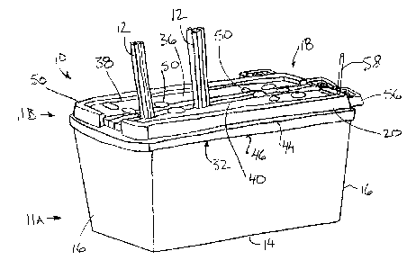
Figure 1 is an isometric view of the display device in an assembled
position shown with elongate threaded rods display therein.

CA 02411610 2002-11-12
-5-
Figure 2 is a top plan view of the display device according to Figure 1.
Figure 3 is a sectional view along the line 3-3 of Figure 2.
Figure 4 is a sectional view along the line 4-4 of Figure 2.
Figure 5 is a top plan view of the display device with the support grid
normally mounted spaced above the base member shown removed.
DETAILED DESCRIPTION
Referring to the accompanying drawings, there is illustrated a display
device generally indicated by reference numeral 10. The device 10 is generally
intended for displaying elongate product materials, for example rigid metallic
threaded rods 12 and the related accessories. The display is intended to be
located
in retail or similar locations for displaying for sale elongate items.
Preferably the
device is for use in a hardware situation where many such elongate items are
sold
including rods, pipes, dowels and the like.
In the illustrated embodiment the display device is formed from a
molded plastic tote box container available under the trademark Rubbermaid.
The
device 10 is molded in two parts. A first part 11A includes a base member 14
in the
form of a generally rectangular floor panel defining the floor of the
container with
integral side walls 16 extending upwardly from the base member 14 on all sides
for
defining a continuous watt structure extending upwardly from a periphery of
the base
member.
A second part 11 B of the device comprises a lid adapted to enclose
the open top end of the first part of the container and is used to form a
support a grid
18 which spans the side walls 16 of the device at a fixed spacing above the
base
member. The support grid 18 thus comprises a panel-like structure having a
peripheral side wall portion 20 arranged for securement to the side walls 16
of the
first part 11 A of the device.

CA 02411610 2002-11-12
-6-
The base member 14 and side walls 16 are molded integrally with one
another with the walls extending upwardly at an outward incline so as to
permit
nesting with the first part of other display devices having a similar
configuration. The
side walls 16 include a shoulder 22 formed therein which extends generally
horizontally spaced upwardly from the base member for added structural
support.
The shoulder 22 defines an internal ledge as the walls are offset outwardly at
the
shoulder 22 at a top end of the container in relation to the bottom end
adjacent the
base member. The shoulder 22 extends the full length of both longer sides 24
of the
device as well as part way across the shorter ends 26 of the display device.
The side walls 16 at the shorter ends 26 of the display device each
include a centrally located vertical channel which meets the shoulder 22 from
each
of the longer sides 24 of the display device. The channel 28 is raised
inwardly in
relation to the side walls 16 and includes a handle portion 30 formed at a top
end
thereof. The channels 28 act as a longitudinally extending rib for added
structural
support to resist bending of the side walls.
A lip 32 is provided about an upper periphery of the side walls 16 at an
open top end of the first part of the display device. The lip 32 curls
upwardly and
outwardly from the side walls 16 about a full periphery of the side walls and
extends
downwardly at a free end 34 spaced outwardly from the side walls 16. The
curved
lip again provides added structural support while the free end 34 includes a
blunt
end for snap-fitting the second part of the display device thereon.
The second part 11 B of the display device generally comprises a rigid
panel 36 which spans the side walls 16 in an assembled position. A peripheral
edge
of the rigid panel 36 is curled upwardly then outwardly and finally downwardly
at a
free end thereof similarly to the lip 32 for added rigidity to the panel 36.
The side
wall portion 20 extends away from the panel 36 at an outward incline from the

CA 02411610 2002-11-12
7
opposing side wall portions so that the side wall portions of the second part
of the
display device flare outwardly for nesting with similar second parts of
display devices
having a similar configuration as noted above with regard to the first part of
the
display device. The rigid panel 36 includes a plurality of longitudinally
extending ribs
40 extending a full length of the panel for added structural support. Each rib
generally comprises an elongate dome-shaped structure formed into the panels.
The panel 36 further includes a handle portion 42 at each end thereof which is
arranged to mate with the handle 30 formed in the side walls 16 of the display
device.
The side wall portions 20 of the rigid panel 36 include a shoulder 44
which extends substantially horizontally outward to a free end 46 which curls
downwardly to define a lip which secures about the lip 32 of the side walls
16. An
inner side of the free end 46 includes a catch 48 for snap-fitting to the free
end 34 of
the side walls. The side wall portions of the rigid panel 36 of the second
part of the
display device can thus be selectively snap-fit to the side walls 16 of the
first part of
the display device.
The support grid 18 is defined by a plurality of apertures 50 in the rigid
panel 36 which form the openings of a grid structure which are suitably sized
to
receive bunches of the threaded rods 12 therethrough. The apertures 50 have
varying diameters for accommodating different sizes and numbers of rods
therein.
A plurality of divider members 52 are provided which are supported on
the base member 14 to extend upwardly therefrom only part way in relation to
the
side walls 16 to form a grid structure similar to the support grid 18. In a
preferred
embodiment the divider members 52 are molded integrally with the base member
14
however as illustrated in the embodiment of Figure 5, a series of plastic
collars 54
may be positioned in an upright orientation in a side by side arrangement
glued to

CA 02411610 2002-11-12
8
the floor for defining a grid structure between adjacent walls of the various
collars
54.
A set of small molded plastic containers 56 are supported on the
shoulder 44 and secured about the rigid panel 36. In various embodiments the
containers 56 may be molded directly into the rigid panel 36 or formed about a
periphery of the panel as illustrated. The containers 56 are suitably arranged
for
containing nuts and washers therein which are intended for use with the
threaded
rods 12. The containers may also be formed as separate elements connected to
the
periphery of the shoulder 44.
A mounting stake 58 is mounted on the rigid panel 3fi in an upright
orientation thereon to extend upwardly in the assembled position of the
display
device. The mounting stake 58 is suitably arranged for supporting annular
members
such as washers stacked thereon about the stake.
In the illustrated embodiment, when displaying elongate product such
as threaded rods, a container is first provided having a base member and side
walls
within which a plurality of the divider members 52 may be mounted as described
above. Apertures 50 are formed into the rigid panel 36 to define the support
grid 18
formed from the lid of the container which may be snap-fit onto the side walls
of the
display device for fully enclosing the interior of the display device. The
support grid
18 is supported on the side walls 16 at a fixed spacing above the base member
14
by either melting the two parts of the display device together or by suitable
fastening
such as glue, screws or other suitable fasteners. The containers 56 and the
stake
58 are further mounted on the display device as described above at which point
the
product may then be displayed on the device. The elongate rods 12 are
displayed
by inserting the rods through a respective aperture 50 and aligning a bottom
end of
the rods between a respective pair of the divider members 52 so that the
bottom end

CA 02411610 2002-11-12
_g_
of the rods may be supported on the base member 14. Mating threaded nuts and
washers for use with the rods are then supported on the stake 58 and within
the
containers 56 as desired.
In alternate embodiments of the display device, the device is preferably
molded into two pieces as described above, but with the containers 56, the
divider
members 52 and the apertures 50 all being formed integrally in the molding
process.
A first part 11A would include the base member 14 and corresponding side wall
portions 16 extending therefrom at an outward incline away from each other for
nesting as described above. The panel forming the base member 14 may be
molded with suitable ribs to define an integral grid formed therein for
restricting
sliding movement of the bottom end of the rods being displayed from sliding
laterally
about on the base member. The second part 11 B of the integrally molded
display
device includes the support grid 18 in which the panel 36 has the apertures 50
therein during the molding process as well as side wall portions 20 which
similarly
extend outwardly from the panel 36 at an outward incline away from one another
for
nesting as described above.
In either arrangement the display device may be stored or transported
in a nested position before being assembled into the assembled position of
Figure 1
in which product may be displayed. The nested position may comprise supporting
one molded part 11A or 11 B within the other, for example nesting the base
member
14 and side walls 16 within the side wall portions 20 extending from the rigid
panel
36, or by nesting each of the parts 11A or 11B with a plurality of like parts
of display
devices having similar configurations.
While some embodiments of the present invention have been
described in the foregoing, it is to be understood that other embodiments are
possible within the scope of the invention. The invention is to be considered
limited

CA 02411610 2002-11-12
-10-
solely by the scope of the appended claims.

Dessin représentatif
Une figure unique qui représente un dessin illustrant l'invention.
États administratifs

2024-08-01 : Dans le cadre de la transition vers les Brevets de nouvelle génération (BNG), la base de données sur les brevets canadiens (BDBC) contient désormais un Historique d'événement plus détaillé, qui reproduit le Journal des événements de notre nouvelle solution interne.

Veuillez noter que les événements débutant par « Inactive : » se réfèrent à des événements qui ne sont plus utilisés dans notre nouvelle solution interne.

Pour une meilleure compréhension de l'état de la demande ou brevet qui figure sur cette page, la rubrique Mise en garde , et les descriptions de Brevet , Historique d'événement , Taxes périodiques et Historique des paiements devraient être consultées.

Historique d'événement

Description Date
Demande non rétablie avant l'échéance 2006-11-14
Le délai pour l'annulation est expiré 2006-11-14
Réputée abandonnée - omission de répondre à un avis sur les taxes pour le maintien en état 2005-11-14
Demande publiée (accessible au public) 2003-05-16
Inactive : Page couverture publiée 2003-05-15
Lettre envoyée 2003-04-16
Inactive : Transfert individuel 2003-03-07
Inactive : CIB attribuée 2003-02-07
Inactive : CIB en 1re position 2003-02-07
Demande reçue - nationale ordinaire 2003-01-09
Inactive : Certificat de dépôt - Sans RE (Anglais) 2003-01-09

Historique d'abandonnement

Date d'abandonnement Raison Date de rétablissement
2005-11-14

Taxes périodiques

Le dernier paiement a été reçu le 2004-11-09

Avis : Si le paiement en totalité n'a pas été reçu au plus tard à la date indiquée, une taxe supplémentaire peut être imposée, soit une des taxes suivantes :

  • taxe de rétablissement ;
  • taxe pour paiement en souffrance ; ou
  • taxe additionnelle pour le renversement d'une péremption réputée.

Les taxes sur les brevets sont ajustées au 1er janvier de chaque année. Les montants ci-dessus sont les montants actuels s'ils sont reçus au plus tard le 31 décembre de l'année en cours.
Veuillez vous référer à la page web des taxes sur les brevets de l'OPIC pour voir tous les montants actuels des taxes.

Historique des taxes

Type de taxes Anniversaire Échéance Date payée
Taxe pour le dépôt - petite 2002-11-12
Enregistrement d'un document 2003-03-07
TM (demande, 2e anniv.) - petite 02 2004-11-12 2004-11-09
Titulaires au dossier

Les titulaires actuels et antérieures au dossier sont affichés en ordre alphabétique.

Titulaires actuels au dossier
PATENT APPLIED TECHNOLOGY
Titulaires antérieures au dossier
DAVID LANGTRY
Les propriétaires antérieurs qui ne figurent pas dans la liste des « Propriétaires au dossier » apparaîtront dans d'autres documents au dossier.
Documents

Pour visionner les fichiers sélectionnés, entrer le code reCAPTCHA :


Pour visualiser une image, cliquer sur un lien dans la colonne description du document (Temporairement non-disponible). Pour télécharger l'image (les images), cliquer l'une ou plusieurs cases à cocher dans la première colonne et ensuite cliquer sur le bouton "Télécharger sélection en format PDF (archive Zip)" ou le bouton "Télécharger sélection (en un fichier PDF fusionné)".

Liste des documents de brevet publiés et non publiés sur la BDBC .

Si vous avez des difficultés à accéder au contenu, veuillez communiquer avec le Centre de services à la clientèle au 1-866-997-1936, ou envoyer un courriel au Centre de service à la clientèle de l'OPIC.

({010=Tous les documents, 020=Au moment du dépôt, 030=Au moment de la mise à la disponibilité du public, 040=À la délivrance, 050=Examen, 060=Correspondance reçue, 070=Divers, 080=Correspondance envoyée, 090=Paiement})


Description du
Document 
Date
(aaaa-mm-jj) 
Nombre de pages   Taille de l'image (Ko) 
Description 2002-11-11 10 422
Revendications 2002-11-11 5 170
Dessins 2002-11-11 3 57
Abrégé 2002-11-11 1 23
Dessin représentatif 2003-02-09 1 15
Certificat de dépôt (anglais) 2003-01-08 1 159
Courtoisie - Certificat d'enregistrement (document(s) connexe(s)) 2003-04-15 1 107
Rappel de taxe de maintien due 2004-07-12 1 110
Courtoisie - Lettre d'abandon (taxe de maintien en état) 2006-01-08 1 174