Note : Les descriptions sont présentées dans la langue officielle dans laquelle elles ont été soumises.
CA 02412870 2002-12-19
WO 01/97654 PCT/GBO1/00185
_J _
A TOILET CLEANING APPARATUS
The present invention relates to a toilet cleaning apparatus.
More particularly, but not exclusively, the present invention
relates to a toilet brush for dispensing a predetermined volume
of cleaning fluid.
Toilet brushes for cleaning the bowls of toilets are well
known. In use, one typically applies a cleaning fluid such as
a disinfectant to a~ toilet bowl and then uses the brush to
clean the bowl. However, such a known brush and associated
cleaning method has the drawbacks that users typically apply
too much cleaning fluid to the howl. This is both expensive
and harmful to the environment. In some countries the use of
bleach as a toilet cleaner is banned for this reason.
US-5984555 discloses a brush comprising a brush head in fluid
communication with a hollow brush handle. In use, a plunger is
urged along the interior of the handle so dispensing fluid from
the handle to the bristles of the brush head. With such a
brush the cleaning fluid is dispensed accurately to the brush
head. However, when using such a brush it ~is difficult to
control the exact amount of cleaning fluid dispensed; the
further one presses the plunger the more fluid~is dispensed.
With such a brush users tend to use too much cleaning fluid
which is harmful to the sewage destroying bacteria in the
sewage system.
CA 02412870 2002-12-19
WO 01/97654 PCT/GBO1/00185
-2-
Accordingly, the present invention provides a toilet cleaning
apparatus comprising
a toilet brush head;
a toilet brush handle separated from the brush head by a brush
shaft;
a portion of the brush handle being adapted to contain a
cleaning fluid and being in fluid communication with the brush
head by a conduit;
the handle being adapted to be reciprocally displaced along the
conduit between a first position remote from the brush head and
a second position proximate to the brush head so urging
cleaning fluid from the handle to the brush head; and,
a non return valve within the conduit adapted to allow the flow
of fluid from handle to brush but to prevent the flow of fluid
from brush to handle.
The apparatus according to the invention has the advantage that
by reciprocally displacing the handle between first and second
positions one can dispense a predetermined amount of cleaning
fluid. This prevents over use of cleaning fluid.
In addition the apparatus according to the invention has the
advantage that the non-return valve prevents the cleaning fluid
from being sucked back into the handle from_the brush so
keeping the contents of the brush handle are kept sterile.
Preferably, the brush handle comprises an air input valve for
introducing air into the brush handle. Such a valve enables
air to be introduced into the handle after cleaning fluid has
been dispensed, so returning the pressure within the handle to
its initial value.
The portion of the handle adapted to contain the cleaning fluid
can be adapted to be detached from the shaft. The portion,
CA 02412870 2002-12-19
WO 01/97654 PCT/GBO1/00185
-3-
once empty, can be simply detached from the cleaning apparatus
and replaced with a full portion.
The non return valve can comprise a plug positioned within the
conduit, the plug being in contact with a seat within the
conduit so preventing the flow of cleaning fluid from the
handle to the brush;
the plug being arranged such that on urging the handle towards
the first position the increase in fluid pressure within the
handle separates the plug from the seat so urging cleaning
fluid to flow from the handle to the brush.
Such a plug provides a simple means of ensuring that the
cleaning fluid can flow from the handle to the brush, but not
in the opposite direction.
The plug can be urged into contact with the seat by means of a
resiliently deformable member, preferably a spring.
The apparatus can further comprise a piston slideable within
the conduit in response to the displacement of the handle
between first and second positions so urging a portion of the
cleaning fluid in a dispensing volume between the piston and
the non return valve through the non return valve. The use of
a slideable piston defining a dispensing volume provides a
reliable means for ensuring a defined volume of cleaning fluid
is dispersed by the apparatus each time the handle is depressed
from the second to first positions. The volume of the
dispensing volume can be arranged to be small, so ensuring that
only a small controlled volume of cleaning fluid is dispensed
when the handle is displaced from the first to second
positions. This reduces the harmful effect of the bleach to
the sewage system.
CA 02412870 2002-12-19
WO 01/97654 PCT/GBO1/00185
-4-
The piston can comprise a non return refill valve adapted to
prevent flow of cleaning fluid from the dispensing volume to
the handle but to allow flow of cleaning fluid from the handle
to the dispensing volume when the fluid pressure within the
handle exceeds the pressure within the dispensing volume by a
predetermined amount. This allows the dispensing volume to be
refilled after each dispensing cycle.
The piston can comprise a refill conduit extending through the
piston allowing the flow of cleaning fluid from the handle to
the dispensing volume; the refill valve preferably comprising
a plug located within the refill conduit urged into contact
with the seat by an urging means so preventing the flow of
cleaning fluid through the refill conduit whilst they are in
contact. The urging means can comprise a resiliently
deformable member, preferably a spring.
The present invention will now be described by way of example
only and not in any limitative sense with reference to the
accompanying drawings in which:
Figure 1 shows in cross section, a toilet cleaning apparatus
according to the invention with the brush handled urged towards
a first position;
Figure 2 shows in cross section a resiliently deformable valve
located with the toilet cleaning apparatus; and
Figure 3 shows in cross section, a toilet cleaning apparatus
according to the invention with the brush handle urged towards
what was the second position.
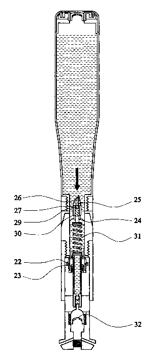
Shown in Figure 1 in cross section are toilet brush shaft (1)
and toilet brush handle (2) portions of toilet cleaning
apparatus according to the invention. The toilet brush~shaft
CA 02412870 2002-12-19
WO 01/97654 PCT/GBO1/00185
-5-
(1) comprises a support wall (3) defining a conduit (4)
extending along the shaft (1) between a toilet brush handle (2)
and the brush head (not shown). Proximate to the toilet brush
head the conduit (4) splits into a number of sub conduits (5)
which lead to apertures (6) opening at a number of points on
the brush head. These ensure that the cleaning fluid which
flows along the conduit (4) towards the brush head is spread
evenly by the sub conduits ( 5 ) over the brush head and onto the
bristles. The portion (7) of the brush shaft (1) comprising
the sub conduits (5) is connected to the remainder of the brush
shaft (1) by a screw thread (8). This enables simple removal
of this portion (7) should it need to be cleaned or replaced.
The brush shaft (1) further comprises a threaded recess (9) for
receiving a screw thread of the brush head. This enables
simple separation of the brush shaft (1) and the brush head
should this be necessary for example to clean or replace the
brush head.
Extending from the opposite end o,f the brush shaft (1) to the
brush head is the brush handle (2). The brush handle (2)
comprises~a hollow portion (10) for containing cleaning fluid.
The outer wall ( 11~) of this portion ( 10 ) is gripped by the user
during use. Extending through the wall (11) of this portion
(10) of the brush handle (2) is an air input valve (12) which
allows the passage of air into the hollow portion ( 10 ) when the
pressure in this portion (10) drops below air pressure.
In threaded engagement with the hollow portion (10) is a
cylinder portion (13). The inner wall (14) of the cylinder
portion (13) defines a further part (15) of the fluid conduit.
This part of the fluid conduit extends between the hollow
portion (10) of the brush handle (2) and the fluid conduit (4)
defined by the brush shaft (1). By means of this conduit
CA 02412870 2002-12-19
WO 01/97654 PCT/GBO1/00185
-6-
cleaning fluid can flow from storage in the brush handle (2) to
the brush head.
The cylinder portion (13) of the brush handle (2) overlaps a
toilet brush shaft (1) forming an airtight seal therebetween.
When applying pressure to the brush handle (2), the handle (2)
can be slid over the brush shaft (1) between the first position
proximate to the brush head and a second position remote from
the brush head.
Located within the conduit is a first seat member (16)
comprising a restriction in the conduit (4) through which the
cleaning fluid must flow. A non return valve (l7) comprising
a first plug (18) is urged into contact with the first seat
member (16) by a first spring (19) as shown. The first spring
(19) urges the first plug (18) into contact with the first seat'
member (16) in a direction away from the brush head. This
ensures that when the cleaning fluid pressure on the brush head
side of the non return valve (17) exceeds that on the opposite
side of the valve (l7) the ffirst plug (18) is urged more ffirmly
into contact with the first seat (16) so preventing fluid flow
away from the brush head. However, when the pressure on the
brush head side of the non return valve (17) is less than that
on the opposite side. The pressure urges the first plug (18)
away from the first seat (16). When the pressure differences
are such that the cleaning fluid applies a force on the first
plug (18) which is greater than the force applied to the first
spring (19), the first plug (18) separates from the first seat
(1~) allowing the flow of cleaning fluid through the first seat
(16) towards the brush head.
Positioned between the first seat (16) and the brush head is a
valve made from a resiliently deformable material, preferably
silicone. The valve is shown in cross section in Figures 2a to
2c. The valve comprises a base sealingly attached to a conduit
CA 02412870 2002-12-19
WO 01/97654 PCT/GBO1/00185
wall surrounding the valve. Positioned within the base is a
deformable crown comprising self sealing lips. In Figure 2a
the pressure on the two sides of the valve is equal and the
sealing lips are inter-engaged preventing the flow of fluid
through the valve. As the pressure on one side of the valve
increases, the valve starts to deform (Figure 2b). Eventually
the valve deforms sufficiently for the Zips to separate
allowing fluid to flow through the valve (Figure 2c). As the
pressure equalises the lips re-seal preventing further fluid
flow. This seal prevents fluid "dripping" from the conduct on
to the brush head if the brush is left standing in a vertical
position for a long period. The air input valve (12) comprises
an identical valve for allowing the entry of air into the
hollow portion of the valve handle.
Also located within the conduit (4) is a piston (20) which
defines a dispensing volume (21) within the shaft (1). A
flange (22) on the piston (20) overlaps a flange (23) on the
brush handle (2) so that displacement of the brush handle (2)
between the first and second positions induces a corresponding
displacement of the piston (20) within the conduit (4).
Extending through the piston (20) is a refill conduit (24)
enable cleaning fluid to flow from the handle (2) to the piston
(20) to the dispensing volume (21). Extending from the refill
conduit (24) is a piercing member (25). A piercing member
conduit (26) extends through the piercing member (25) as shown.
The joint between the piercing member conduit (26) and the
refill conduit (24) defines a refill seat (27). A refill valve
(28) comprising a refill plug (29) is urged into contact with
the seat (27) by means of a refill spring (30). When the fluid
pressure within the dispensing volume (21) exceeds that in the
handle (2) the refill plug (29) is urged further into contact
with the refill seat (27) so preventing flow along the roof of
conduit (24). If however, the pressure in the handle (2)
exceeds that in the dispensing volume (21) by a sufficient
CA 02412870 2002-12-19
WO 01/97654 PCT/GBO1/00185
_g_
degree to overcome the action of the refill spring (30) then
the refill plug (29) will separate from the refill seat (27)
allowing fluid to flow from the handle (2) into the dispensing
volume (21).
Finally, also positioned within the conduit (4) is a piston
spring (31) which urges the piston (20) away from the brush
head. The function of this is described in detail below.
In use the handle portion ( 10 ) containing cleaning fluid is ~~,
threadably engaged within the associated cylinder portion (13)
of the brush handle. As the portions (10,13) are threaded
together the piercing member (25) pierces a thin foil cap (not
shown) allowing cleaning fluid to flow from the handle portion
(10) .
Initially, the cleaning fluid will flow along the piercing ,
member conduit (26) to the refill valve (28). Assuming the
fluid pressure in the handle portion (2) is greater than that
in the dispensing volume (21) the fluid pressure will open the
refill valve (28) allowing fluid to flow into the dispensing
volume (21) until the fluid pressures in the handle (2) in the
dispensing volume (21) are substantially equal.
As no force is being applied to the handle (2) the piston
spring (31) urges the piston (20) and the handle (2) away from
the brush head as shown in Figure 1.
In order to dispense cleaning fluid from the handle (2) to the
brush head, the brush head is held stationery and the handle
(2) urged towards the head. Displacement towards the handle
( 2 ) wraps the piston ( 20 ) towards the brush head as shown in
Figure 3. This reduces the dispensing volume (21) causing the
fluid pressure within the dispensing volume to rise.
Eventually, the pressure within the dispensing volume (21) is
CA 02412870 2002-12-19
WO 01/97654 PCT/GBO1/00185
-9-
sufficient to allow the first plug (18) to separate from the
first seat (16). This enables the cleaning fluid to flow from
the dispensing volume (21) through the diaphragm (32) along the
sub conduits (5) and onto the brush head. During this time the
refill valve (28) remains closed preventing the flow of
cleaning fluid from the handle to the dispensing volume (21).
Hence, as the cleaning fluid flows onto the brush head the
fluid pressure within the dispensing volume (2) drops and
eventually the refill valve (28) closes.
In order to complete the action the handle (2) is then urged to
the second position away from the brush head. This causes a
corresponding displacement in the piston (20) so increasing the
dispensing volume (21). As both the non return and refill
valves (17,2.8) are closed; this causes closes a drop in
pressure~in the dispensing volume (21). Once the pressure in
the dispensing volume drops sufficiently for the pressure
difference across the refill valve (28) to cause the refill
pump (29) to separate from the refill seat (27) allowing
cleaning fluid to flow from the handle (2) to the dispensing
volume (21). Once the fluid pressure the dispensing volume
(21) is substantially equal to that in the handle the refill
valve (28) closes.
Finally, since cleaning fluid has passed from the handle (2) to
the dispensing volume (21) the fluid pressure within the handle
(2) will have dropped. Consequently, the air input valve (12)
opens allowing air to flow into the handle (2) until the
pressure within the handle (2) returns to its initial value so
completing the dispensing cycle.