Note : Les descriptions sont présentées dans la langue officielle dans laquelle elles ont été soumises.
CA 02412912 2002-12-13
WO 02/01750 PCT/USO1/19991
-1
DOPPLER CORRECTION FOR AIRBORNE CELLULAR SYSTEM
Field of the Invention
The present invention relates generally to a cellular communications system
including an airborne repeater, and particularly to compensation of airborne
repeater links.
Background of the Invention
The increasing need for communications networks and capabilities in outlying
and geographically diverse locations has created greater demand for cellular
systems. Many new carriers providing the infrastructure for such systems have
focused their resources on building as many terrestrial cell stations as
possible to
expand their respective areas of coverage and consequently generate more
revenue.
However, the buildout rate for the terrestrial cell stations is typically slow
and
expensive, especially in mountainous or otherwise difficult ~to access areas.
In
addition, in some these areas, a carrier's return on investment may not
provide the
incentive necessary for the carrier to build the necessary cell stations,
thereby
leaving these areas with either limited or no cellular service at all.
Further, many
areas having a sufficient number of cellular communications base transceiving
stations to handle calls during both off-peak and peak times cannot adequately
handle large volumes of calls during sporting events or other short-term
special
events that temporarily attract large crowds.
In response to the above, airborne cellular systems have been proposed in
which a cellular repeater mounted in an airplane, executing a predetermined
flight
pattern over a geographic area requiring cellular coverage, links calls from
cellular
phones within the geographic area to a terrestrial base station. Because the
airplane is capable of traversing geographic obstacles and takes the place of
the
cell stations, such a system overcomes the above-mentioned limitations of
conventional terrestrial cellular systems.
Despite its many advantages, an airborne cellular system presents design
and implementation problems not present in the design and implementation of
CA 02412912 2002-12-13
WO 02/01750 PCT/USO1/19991
-2-
conventional terrestrial cellular systems. For example, an airborne cellular
system
requires both a high frequency feeder link to link the base station and the
system
switch to the airborne repeater, and a subscriber or user link to link the
airborne
repeater to cellular phones within the area of coverage. As a consequence of
the
motion of the airplane relative to the base station or cellular phone, an
often
significant amount of Doppler shift is introduced on the links. As a cellular
system
such as a TDMA EIA 136 system is sensitive to Doppler shift characteristics,
its
performance is degraded generally in proportion to the amount of Doppler shift
present.
In addition, as the airborne repeater moves as the plane executes its flight
pattern, the communication path link distances between the base station and
the
airplane and the airplane and the system subscribers constantly change. These
changes in path link distances cause signal loss to vary. Also, airplane
pitch, roll
and yaw can move a beam off of its peak gain, thereby increasing the average
power consumption of the repeater and associated equipment, increasing dynamic
range requirements and increasing the dynamic range and power consumption of
the repeater and associated equipment. Consequently, heavier, more expensive
and higher power consumption power amplifiers must be used.
Clearly, a need exists for solutions to the foregoing problems.
Brief Description of the Drawings
Advantages of the present invention will be readily apparent from the
following detailed description of preferred embodiments thereof when taken
together
with the accompanying drawings in which:
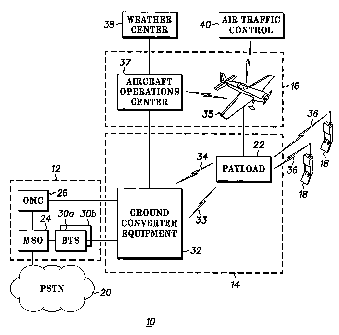
FIG. 1 is a system diagram of an airborne cellular communications system of
the type in which Doppler shift is corrected in accordance with the present
invention;
FIG. 2 is a block diagram illustrating the components of the airborne cellular
communications system shown in FIG. 1 in more detail;
FIG. 3 is a diagram illustrating how and where Doppler shift is generated in
the system shown in FIG. 1;
FIG. 4 is a block schematic diagram of the components utilized to correct the
Doppler shift shown in FIG. 3;
CA 02412912 2002-12-13
WO 02/01750 PCT/USO1/19991
-3-
FIG. 5 is a diagram showing the system of FIG. 1 providing uninterrupted
coverage over a predetermined geographic area due to signal path loss
compensation provided in accordance with the present invention;
FIG. 6 is a flow diagram of a methodology for a telemetry data-based
technique for pre-compensation of feeder link beam path loss; and
FIG. 7 is a flow diagram of a methodology for a pilot signal amplitude-based
technique for pre-compensation of feeder link beam path loss.
Detailed Description of the Preferred Embodiments
Referring now to the drawings in which like numerals reference like parts,
FIG. 1 shows an airborne cellular communications system 10. The system 10
generally includes three primary segments: a cellular infrastructure segment
12, a
radio infrasfiructure segment 14, and an airplane segment 16. These three
segments in combination are capable of providing cellular communications
coverage to a large geographical area by enabling system users, represented
generally by handsets 18, to link to a public switched telephone network
(PSTN) 20
via an airplane payload 22 including a repeater. The structure and function of
each
of these three system segments will be discussed in detail.
The cellular infrastructure segment 12 includes a mobile switching office
(MSO) 24 that includes equipment, such as a telephony switch, voicemail and
message service centers, and other conventional components necessary for
cellular
service. The MSO 24 connects to the PSTN 20 to send and receive telephone
calls
in a manner well known in the art. In addition, the MSO 24 is connected to an
operations and maintenance center (OMC) 26 from which a cellular system
operator
manages the cellular infrastructure segment 12. The MSO 24 is also connected
to
one or more base transceiver stations (BTSs) such as the BTSs shown at 30a,
30b.
The BTSs 30a, 30b transmit and receive RF signals from the system users 18
through the radio infrastructure segment 14.
More specifically, the BTSs 30a, 30b transmit and receive RF signals through
ground converter equipment 32. The ground converter equipment 32 converts
terrestrial cellular format signals to C-band format signals and communicates
with
the airborne payload 22 through a feeder link 33 and a telemetry link 34, each
of
which will be discussed later in detail. The payload 22 establishes a radio
link 36 for
CA 02412912 2002-12-13
WO 02/01750 PCT/USO1/19991
-4-
connecting calls over a wide geographic area of coverage, or footprint, that
is
capable of exceeding 350 km when the airplane maintains a flight pattern at or
around 30,000 feet above the ground.
In addition to the airplane 35, the airplane segment 16 also includes an
airplane operations center 37 that controls mission logistics based at least
in part on
information from sources such as a weather center 38, and manages all system
airplanes, as the system preferably includes three airplanes to ensure
continuous
coverage. The airplane also receives additional routine instructions from
sources
such as an air traffic control center 40.
FIG. 2 shows certain components of the system 10 in more detail.
Specifically, the ground converter equipment 32 includes a C-band antenna 42
for
receiving/transmitting signals fromlto the payload 22 (a second antenna is
also
provided for redundancy purposes), and a C-band converter 44 for appropriately
converting the signals received from or to be transmitted to the payload 22.
According to a preferred embodiment, the C-band antenna 42 and the converter
44
enable 800 MHz airborne cellular antennas 70 to communicate with the BTSs 30a,
30b via an established downlink, or feeder link, 33, and the converter 44
upconverts
nominal signals from the BTSs 30a, 30b to C-band signals before the signals
are
transmitted to the airplane 35. Also, each BTS 30a, 30b is assigned a
different
band in the C-band spectrum so that signals from the different BTSs 30a, 30b
can
be separated and routed to the correct antenna, such as the antenna 56, at the
payload 22. In addition, the ground control equipment 32 includes telemetry
components such as a telemetry antenna 46, a telemetry modem 48 and a
telemetry processor 50 to receive and process airplane data transmitted from
an
airplane telemetry antenna 52, while a processor 54 controls transmission of
the
processed telemetry data to the OMC 26 and the airplane operations center 37.
In the airplane segment 16,. the airplane telemetry antenna 52 mentioned
above transmits airplane avionics data generated by airplane avionics
equipment,
represented generally at 58, including airplane location, direction and flight
pattern
data as well as other data such as airplane pitch, roll and yaw data. The data
from
the airplane avionics equipment 58 is input into and processed by a payload
processor 60 before being output to the telemetry antenna 52 through a
telemetry
modem 62. The payload processor 60 is also responsible for processing signals
transmitted to and received from the ground converter equipment 32 through the
CA 02412912 2002-12-13
WO 02/01750 PCT/USO1/19991
-5-
feeder link 33 established between the C-band antennas 42, 56 and for
processing
signals transmitted to and received from the system users 18 through a
downlink, or
user link, 69 established between the users 18 and a payload downlink antenna
such as an 800 MHz antenna 70, with the signals received by and transmitted
from
the payload being appropriately upconverted or downconverted by an 800 MHz
converter 72. The payload 22, in addition to including the above-mentioned
equipment, also includes GPS equipment 74 that can also be input into the
processor 60 and transmitted to the ground converter equipment 32 or to the
airplane operations center 37 for flight control and/or monitoring purposes.
The
components shown in the airplane and in the payload together form the airplane
repeater that enables cellular coverage to be provided to a large geographic
area
that may otherwise not support terrestrial cellular coverage due to an
insufficient
number of cell stations or the like.
As should be appreciated from the system configuration shown in FIGs. 1
and 2, both the airborne cellular system 10 and conventional terrestrial
cellular
systems appear identical to the PSTN 20 and the system users 18. In other
words,
there are no discernable service-related differences between calls linked to
the
PSTN 20 through the cellular infrastructure, radio infrastructure and airplane
segments 12-16 and calls handled through a conventional terrestrial system
infrastructure, in part due to the fact that the cellular infrastructure
segment 12
includes a standard telephony switch in the MSO 24 and BTSs 30a, 30b that are
identical or nearly identical to those included in a conventional terrestrial
system
infrastructure.
Still referring to FIGs. 1 and 2, operation of the components of the airborne
cellular system 10 during completion of a call made by one of the system users
18
will now be described. The airplane 35 when on-station preferably flies in a
circular
or near circular flight pattern (although the flight pattern may vary
according to
specific weather and coverage conditions) to provide coverage to a
predetermined
geographic area during a mission. While it is on-station, the airplane
maintains
contact with the ground converter equipment 32 to provide both the feeder link
33
and the user link 36 for the cellular infrastructure segment 12 through the
radio
infrastructure equipment segment 14. The airplane 35 also transmits a
predetermined number of communications beams, such as, for example, 13 beams,
over the coverage area, with each beam being assigned to a sector of one of
the
CA 02412912 2002-12-13
WO 02/01750 PCT/USO1/19991
-6-
BTSs 30a, 30b and having its own set of control and traffic channels to carry
signaling and voice data between the system users 18 and the cellular
infrastructure
segment 12. As the airplane 35 moves in its flight pattern, the beams radiated
from
the airplane rotate. Therefore, the system users 18 will "see" a different
beam every
45 seconds or so and the cellular infrastructure segment 12 performs a sector
to
sector handoff of the call to keep the call from being dropped.
When initiating a call,~a system user, such as one of the users 18, utilizes
the
control channels in the beam to signal the MSO 24 to request a call setup. The
request is sent from a handset of the user 18 to the airplane payload 22, and
then is
relayed to the ground converter equipment 32. The ground converter equipment
32
relays the request to the corresponding BTS, such as the BTS 30a. The BTS 30a
then transmits the request to the MSO 24, which sets up the call with the PSTN
20.
The payload 22 therefore simply extends the physical layer of the BTS 30 'to
the
users 18 to allow a much wider area of coverage than would typically be
provided
by a conventional terrestrial system, and with less associated infrastructure
buildout
cost. The airborne system 10 is therefore specifically useful for providing
temporary
cellular coverage for special events areas, where coverage is only needed for
several days, thereby eliminating the need and cost associated with erecting
cell
stations and then tearing the cell stations down after the special events end.
Once the call setup is completed, voice communication with the PSTN 20
through the traffic channels in the beam is initiated, and voice information
is then
relayed in the same manner as the signaling information. When the call ends, a
signal is sent to the MSO 24 to tear down the call, the handset of the user 18
releases the traffic channel used for voice communications, and the channel is
returned to an idle state.
Referring to FIGs. 3 and 4, correction of a Doppler shift that is introduced
in
both forward and reverse, user and feeder links due to airplane motion will
now be
discussed with respect to a preferred embodiment in accordance with the
present
invention. Feeder link Doppler shift varies over time with the speed and
direction of
the airplane with respect to the ground converter equipment 32, and may be
either
positive (when beams are headed toward the airplane or the distance from the
airplane to the converter equipment is decreasing) or negative (when beams are
headed away from the airplane or where the distance from the airplane to the
converter equipment is increasing) as the airplane 35 executes its flight
pattern. As
CA 02412912 2002-12-13
WO 02/01750 PCT/USO1/19991
-7-
the Doppler shift is proportional to the center frequency of the signal being
transmitted, the Doppler shift in the system 10 will be significant. User link
Doppler
shift is smaller and relatively constant on a per beam basis. In other words,
airplane
velocity-induced Doppler shift within a beam tends to be similar for all users
covered
by the beam. As will now be described, the present invention is capable of
correcting for both feeder link and user link Doppler to ensure continuous
coverage
is maintained over the designated geographic area.
Referring to the forward link including both forward feeder and user links,
the
BTS 30a transmits a signal to a forward ground converter 44a, which is a
component of the ground converter 44. The forward ground converter 44a steps
the
signal to a higher C-band frequency before the signal is transmitted over the
feeder
link 33 by the C-band antenna 42 (FIG. 2). As shown in FIG. 4, the C-band
antenna
is part of the forward payload converter 72a, which in turn is a component of
the 800
MHz converter 72. Time-varying Doppler shift is typically induced on the
feeder link
due to the movement of the airplane 35 with respect to the base station 30a.
The
forward payload converter 72a then converts the C-band frequency signal back
to a
UHF frequency before the signal is transmitted by the antenna 70 (FIG. 2) to a
handset of the user 18 through the user link 36.
As shown in fihe reverse link in FIG. 4, which includes both reverse feeder
and user links, the handset of the user 18 in return communicates with the
cellular
infrastructure segment 12 in FIG. 1 by transmitting a UHF signal back to the
antenna 70 (FIG. 1 ) through the reverse user link 36. A reverse payload
converter
72b, which is a component of the converter 72 and which includes the C-band
antenna 42, then steps up the signal to the C-band before sending the signal
to the
reverse ground converter 44b through the reverse feeder link 33. The reverse
ground converter 44b, which is also a component of the converter 44, then
converts
the signal back to a UHF signal before the signal reaches the BTS 30a.
In a preferred embodiment in accordance with the present invention, in
addition to the above airborne cellular system protocol, a C-band pilot
reference
signal is generated at 90 by the processor 60 and is transmitted over the
antennas
56, 42 to the processor 54. Preferably, the C-band pilot reference signal is a
signal
in a guard band between cellular communications channels. The processor 54
precisely measures the frequency of the received pilot signal. As both the
airplane
and all ground converters use precise frequency references, such as, for
example,
CA 02412912 2002-12-13
WO 02/01750 PCT/USO1/19991
-$-
GPS-based references, and as the frequency of the pilot signal is known, the
measured frequency can be compared to the known transmitted frequency to
calculate feeder link Doppler shift. After the amount of Doppler shift in the
pilot
reference signal is determined, the processor 54 transmits an error
correctiori value
based on the calculated Doppler shift to the reverse ground converter 44b to
enable
the reverse ground converter 44b to correct for the Doppler shift in the C-
band
signal received from the antenna 42 based on the error correction value.
In addition, the processor 54 also determines the Doppler correction value for
the forward ground converter 44a based on the frequency difference between the
forward and reverse feeder links. The forward ground converter 44a then
provides
a forward-looking shift to the stepped-up C-band signal before the Doppler
shift
occurs on the feeder link 33. Therefore, the forward ground converter 44a pre-
compensates for the Doppler shift that occurs in the feeder link 33 based on
the
Doppler shift present on the transmitted pilot frequency reference signal.
While Doppler shift is determined above based on a pilot frequency reference
signal generated by and transmitted from the processor 60, it should also be
appreciated that an airplane telemetry signal generated by the processor 60
and
transmitted from the telemetry antenna 52 may alternatively be used by the
processor 54 to calculate Doppler shift associated with signals transmitted
over the
user link 69. In this case, the Doppler shift is calculated based on telemetry
data
from the aircraft containing its position and velocity vector, or other
information as
suitable for calculating aircraft motion induced Doppler shift. Also, the
Doppler shift
and error correction value calculations may alternatively be performed by the
processor 60 in the airplane 35 rather than by the processor 54 on the ground.
As mentioned above, the present invention also compensates for Doppler
shift on the forward and reverse user links. Each communication beam in the
system 10 uses a different sub-band of the feeder link. As Doppler shift on
the user
link cannot be calculated exactly because the location of each user is not
exactly
known, Doppler correction is applied by the forward and reverse ground
converters
44a, 44b for each beam by taking into account the expected, or average,
Doppler
shift of the user links on a per beam basis and based on the fact that Doppler
shift
characteristics of each beam are determined by the beam pointing direction
relative
to the velocity vector of the airplane. These calculations are performed
either
CA 02412912 2002-12-13
WO 02/01750 PCT/USO1/19991
_g_
terrestrially in the ground converter equipment 32 or alternatively in the
airplane 35
by the processor 60.
As a result, the present invention is capable of precisely correcting for
feeder
link Doppler shift and of correcting for user link Doppler shift on an average
basis in
each subscriber beam. It should be appreciated, however, that user link
Doppler
shift correction can alternatively be performed in accordance with the present
invention by determining the exact location of each user within the coverage
area of
each beam to exactly remove Doppler shift, if such precision is required by
system
parameters and if the additional equipment and system costs necessary to
perForm
the required calculations are within budgetary parameters.
Referring to FIG. 5, a method of compensating for communications signal
path loss variations on the forward feeder link according to another preferred
embodiment in accordance with the present invention will now be discussed.
Specifically, as the airplane 35 executes its predetermined flight pattern,
the
distances between the airplane 35, the BTS 30a and the users 18 vary,
therefore
causing the signal path loss to vary. In addition, airplane pitch, roll and
yaw often
can move beams from the airplane repeater off of their respective peak gains.
In view of the above, the present invention provides for pre-compensation of
forward feeder link beam path loss by either (1) using telemetry data
including
airplane position data to calculate the expected path loss before adjusting
the
forward ground converter 44a to compensate for the path loss, or; (2)
measuring the
amplitude of the pilot signal to estimate path loss via signal measurement,
and then
adjusting the gain of the forward ground converter 44a accordingly.
FIGs. 6 and 7 illustrate the methodologies used to implement the above
discussed telemetry data-based and pilot signal amplitude-based path loss
compensation techniques, respectively. In FIG. 6, at 100 the processor 54
receives
the airplane telemetry data containing airplane position data from the
airplane 35.
At 102, the processor 54 calculates the expected path loss based on the
distance
between the airplane and a terrestrial base station such as the base station
30a.
Subsequently, at 104 the processor adjusts the gain of the forward ground
converter
44a based on the expected path loss to pre-compensate for feeder link path
loss.
It should be noted at this point that it is also typically important to pre-
correct
the reverse feeder link signal, as such a correction will improve the dynamic
range
of an AGC (not shown) included in the BTSs. Such a pre-correction can be
CA 02412912 2002-12-13
WO 02/01750 PCT/USO1/19991
-10-
performed on the ground using a pilot signal such as the pilot reference
signal 90 or
in the airplane 35 using airplane telemetry data. Performing such pre-
correction is
preferably performed in the airplane, however, because overall airplane power
consumption is reduced, as, for example, antenna transmitting power is scaled
back
when the airplane is near the ground converter equipment 32.
The methodology for the pilot signal amplitude-based path loss
compensation technique is shown in FIG. 7. At 110, the processor 54 measures
the
power level of the received pilot signal generated by the airplane on the
reverse link
and transmitted to the reverse ground converter 44b. Next, at 112 the
processor 54
calculates the reverse feeder link path loss and uses the calculafied value to
calculate forward link path loss. At 114, the gain of the forward converter
44a is
adjusted based on the calculated forward feeder link path loss.
According to an alternate embodiment in accordance with the present
invention, an automatic gain control circuit may be implemented in the
airplane
payload to remove antenna pointing error effects on gain that cannot be
calculated
based on airplane position. The AGG would operate by measuring the power level
on a single control channel transmitted by a BTS and adjusting the gain so
that the
power level as measured at the antenna 52 of that control channel is constant.
Additionally, all path loss compensation calculations may be performed by the
processor 60 in the airplane 35 rather than through a terrestrial-based
operation.
Further, although the above discussion was directed to only path loss
compensation on the feeder link, the present invention may also be used to
compensate for forward and reverse user link path losses, although it is
contemplated that such losses will typically be handled at the handsets of the
users
18. Regardless of the implementation, the link path loss compensation
techniques
of the present invention minimize the required system dynamic range and
therefore
minimize system cost and power requirements.
While the above description is of the preferred embodiment of the present
invention, it should be appreciated that the invention may be modified,
altered, or
varied without deviating from the scope and fair meaning of the following
claims.