Note : Les descriptions sont présentées dans la langue officielle dans laquelle elles ont été soumises.
B25162I~
CA 02413823 2002-12-10
DRAINAGE MAT AND MORTAR BLOCKER
TECHNICAL FIELD AND INDUSTRIAL
APPLICABILITY OF THE INVENTION
The present invention relates to a drainage mat and mortar Mocker. More
particularly, it a drainage mat which acts as a continuous drainage medium and
a barrier to
construction debris when inserted into a wall cavity.
BACKGROUND OF THE INVENTION
The concept of placing drainage systems and debris inhibiting systems in wall
cavities is well-known. For instance, U.S. Patent 5,860,259 illustrates a
planar insulating
board constructed of an insulated section and a drain structure for use in
masonry walls.
The insulated section is constructed of extruded or expanded polystyrene and
the drain
structure is fabricated of a matted material such as strands of polymer, that
is,
polyethtylene, nylon or polyester. The drain structure is attached to the
insulated section
by an adhesive.
U.S. Patent 4,704,048 illustrates a panel assembly inserted on the exterior
surface
of a wall. The assembly includes an insulating board with channels on one side
of the
board. A water-pervious fabric is attached to the channelled side of the
board. The panel
assembly collects water and channels it downward and away from the wall.
U.S. Patent 5,857,297 describes an elastomeric, water-impervious coating which
is
applied to the outer surface of a foundation wall. Sheets of water-impervious
protection
board, formed from thermoplastic resin, are then bonded to the elastomeric
coating. The
proctection boards function to protect the elastomeric coating from damage
during
backfilling. Further, the protection boards contain holes and channels that
serve to
facilitate the movement of water downward away from the wall.
U.S. Patent 6,238,766 illustrates a high-strength geomembrane constructed from
a
blend of polyethylene copolymers. The geomembrane is installed on a foundation
wall
and serves to protect wall waterproofing systems from impact of debris from
backfilling,
earth movement and cracks.
U.S. Patent 5,598,673 describes a masonry cavity wall construction which
prevents
water damage to building foundations and blocks construction debris from
entering the
cavity. The air space, bewteen the masonry cavity wall and the interior wythe,
contains
board insulation to which is attached a polymeric fluiding conducting mesh.
The mesh
B25162A
CA 02413823 2002-12-10
allows gases and water to pass through but prevents solid materials, such as
construction
debris, from passing through it.
U.S. Patent 5,615,525 illustrates a thermoplastic foam board containing
channels
which extend into the board. The panel is installed on the exterior surface of
a foundation
wall with the channels abut and open toward the backfill soil. The channels
vary in width
so as to prevent backfill soil from entering the channels while still
providing effective
water drainage.
All of the above patents teach methods and apparatus for providing drainage
for
walls and/or blocking debris from entering wall cavities and/or providing
insulation for
walls. However, none of the prior art specifically addresses an apparatus for
providing
wall insulation, water drainage and preventing substantially all debris from
blocking the
drainage of water from the wall cavity. Further, none of the prior art suggest
providing a
gap, free of debris, between the interior and exterior wall and below the
drain material, to
permit water to exit the wall cavity.
None of the prior art teach or suggest a product that utilizes a folded flap
that
remains out of a contractor's way while he/she constructs an exterior wall.
The prior art
does not teach or suggest a product that completely blocks the cavity of a
wall to permit
drainage and collect construction debris. Further, none of the prior art
suggest an
adjustable product that can be applied to wall cavities that are small in
size, that is, one
2o inch to three inches across.
Thus, there is a need for a drainage mat that provides superior water
drainage,
debris-blocking capability and insulation in a simple product that can be
easily installed in
a wall cavity.
SUMMARY OF THE INVENTION
The present invention relates to a method and apparatus to provide insulation,
drainage and debris blocking capability. More particularly, the invention
relates to a
drainage mat and mortar Mocker including a panel and polymeric drainage mat
which
includes protrusions on the front side and indentations, corresponding to the
protrusions,
on the back side of the mat. A'filter fabric is affixed the protrusions. The
top portion of
the back side of the drainage mat is affixed to the panel and the bottom
portion of the mat
is folded upward so as to form a U-shape. 'The U-shape is held in place by
connections
25162A
CA 02413823 2002-12-10
extending from the back side of the bottom portion of the drainage mat and
into the front
side of the drainage mat.
It is an object of the present invention to provide an apparatus that provides
drainage and debris-blocking capabilities in a single product.
It is an object of the present invention to provide an apparatus that utilizes
a folded
flap that remains out of a contractor's way while he/she constriicts.an
exterior wall.
It is an object of the present invention to provide an apparatus that
completely
blocks the cavity of a wall to permit drainage and collect construction
debris.
It is an object of the present invention to provide an adjustable product that
can be
applied to wall cavities that are small in size, that is, one inch to three
inches across.
It is an object of the present invention to provide an apparatus that blocks
debris so
that the gap at the bottom of a wall cavity is open for drainage.
It is another object of the present invention to provide a drainage and debris-
blocking apparatus that is easy to install.
It is a further object of the present invention to provide a drainage and
debris-
blocking apparatus that may be conveniently installed on an insulation panel.
The foregoing and other advantages of the invention will become apparent from
the following disclosure in which one or more preferred embodiments of the
invention are
described in detail and illustrated in the accompanying drawings. It is
contemplated that
variations in procedures, structural features and arrangement of parts may
appear to a
person skilled in the art without departing from the scope of or sacrificing
any of the
advantages of the invention.
BRIEF DESCRIPTION OF DRAWINGS
Fig. 1 is a perspective view of the drainage and mortar blocker affixed on an
insulation panel.
Fig. 2 is a side view of the drainage and mortar Mocker as installed in a
typical
wall cavity.
Fig. 3 is a perspective view of the front side of the drainage mat.
Fig. 4 is a perspective view of the front side of the drainage mat.
Fig. 5 is a front view of the back side of the drainage mat.
In describing preferred embodiments of the invention, which are illustrated in
the
drawings, specific terminology is resorted to for the sake of clarity.
However, it is not
3
325162A.
CA 02413823 2002-12-10
intended that the invention be limited to the specific terms so selected and
it is to be
understood that each specific term includes all technical equivalents that
operate in a
similar manner to accomplish a similar purpose.
Although preferred embodiments of the invention are herein described, it is
understood that various changes and modifications in the illustrated and
described
structure can be affected without departure from the basic principles that
underlie the
invention. Changes and modifications of this type are therefore deemed to be
circumscribed by the spirit and scope of the invention, except as the same may
be
necessarily modified by the appended claims or reasonable equivalents thereof.
DETAILED DESCRIPTION OF INVENTION
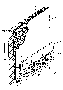
Fig. 1 is a perspective view of the drainage mat and mortar blocker 4, in
accordance with an embodiment of the present invention. The drainage mat and
mortar
Mocker includes a drainage mat 4 and filter fabric 18.
Drainage mat 4 is more clearly illustrated in Figs. 3 and 4. Fig. 4 shows the
front
side S of the drainage mat 4. Drainage mat 4 may be constructed of any
flexible material
that is impervious to water including thermoplastic materials. The preferred
material used
for the drainage mat is high density polystyrene. Drainage mat 4 contains
protrusions 12
with apertures 10 randomly positioned between the protrusions 12. Fig. S shows
the back
side 3 of drainage mat 4. Depressions 16 on the back side 3 of the drainage
mat 4
correspond with the protrusions 12 of the front side 5 of the drainage mat 4
(Fig. 4). As
shown in Figs. 1 and 3, filter fabric 18 is affixed, by an adhesive, to
protrusions 12 on the
front side S of the drainage mat 4. Filter fabric 18 may be any suitable
material which is
pervious to water but impervious to solids. In a preferred embodiment; the
filter fabric is
constructed of polypropylene however, other materials suitable for a filter
fabric include
polyester and polyethylene. In Fig. 3, filter fabric 18 is pulled back for
illustration
purposes only. As illustrated in Fig. 1, the filter fabric 18 extends over the
edge 11 of the
bottom portion 20 on the back side 3 of the drainage mat.
As shown in Figs. 1 and 2, drainage mat 4 may be affixed to a panel 2. The
panel
may be constructed of any suitable material that can be easily affixed to a
wall and/or
provide insulation to a wall including, but not limited to, fibrous material
such as glass
fibers and cellulose fbers, composite materials, plywood or gypsum sheathing,
expanded
polystyrene rigid insulation, extruded polystyrene rigid insulation or
polyisocyanurate
4
825162A
CA 02413823 2002-12-10
rigid insulation. In the present invention, the preferred panel is an expanded
polystyrene
foam insulation board, such as that found in commonly-owned U.S. Patent
6,268,046.
Turning to Figs. 1, 3 and 4, drainage mat 4 includes a top portion 22 and a
bottom
portion 20. As illustrated in Fig. l, the top portion 22 is affixed a panel 2
by any
conventional means, such as an adhesive. It should be noted, however, that the
drainage
mat does not have to be affixed to a surface, the mat may simply rest in a
wall cavity. The
bottom portion 20 of the back side 3 of drainage mat 4 is folded upwardly
adjacent from
said top portion 22 of the panel 2. Fox the purposes of this invention, the
term "adjacent"
has the meaning close to, next to, lying near, contiguous or adjoining. In a
preferred
embodiment, the bottom portion 20 forms a U-shape. Connections such as sewing,
staples, string, tape, ties, weak adhesives and any other material capable of
retaining the
fold, which may be easily severed, may be used. Preferably clips 6 are used,
which are
inserted during manufacture of the mat, extend through the filter fabric 18 on
back side 3
of the bottom portion 20 and through the filter fabric 18 and into the front
side 5 of the
drainage mat 4 thereby retaining the U-shape.
Turning now to Fig. 2, the wall system 7 shows the drainage mat and mortar
Mocker as it is typically installed in a wall cavity. The drainage mat and
mortar blocker
may be installed on a panel 2, affixed to the interior wythe 26 itself or
simply placed into
the wall cavity. The wall system includes an exterior wythe 28, drainage mat
and mortar
blocker 4, an exterior sheathing 24, flashing 34 and interior wythe 26. All of
the
components of the wall system 7 are supported by studs 32.
In Fig. 2, the drainage mat and mortar blocker 4 is installed between an
interior
wythe 26 and exterior wythe 28. In a preferred embodiment, interior wythe 26
may have
an exterior sheathing 24 affixed to its exterior surface to prevent water from
entering the
interior wythe 26. Exterior sheathing 24 can be constructed of any suitable
material that is
impervious to water including, but not limited to, laminated polymeric
material, polymeric
films, plywood, gypsum sheathing, and oriented strand board (OSB) sheathing.
The
interior wythe 26 is typically constructed of wood, plastic, steel, or
masonry. In a
preferred embodiment, panel 2 is affixed to the exterior sheathing 24 on the
interior wythe
26 with the drainage mat 4 facing the exterior wythe 28. The interior and
exterior wythe
define a wall cavity 36 which may be any width. The present invention can used
utilized
in any width of wall cavity. In a preferred embodiment, the wall cavity is
between about
one to about three inches wide. The bottom portion 20 of the drainage mat
extends into
325162A,
CA 02413823 2002-12-10
the bottom of cavity 36 between the exterior wythe 28 panel 2. Flashing 34
extends under
exterior wythe 28, the bottom surface of the cavity 36 and under the panel 2.
As shown in Fig. 2, the exterior wythe 28 is partially constructed prior to
installing
the drainage mat and mortar blocker 4. After the mat and mortar blocker 4 has
been
installed, construction of the exterior wythe 28 is completed and clips 6 are
broken or cut,
allowing the bottom portion 20 to release and at least partially abut exterior
wythe 28.
Alternatively, the drainage mat and mortar blocker can be installed prior to
constructing
the exterior wythe however, the exterior wythe should be installed one or two
courses high
before the clips are severed allowing the bottom portion 20 to release.
The exterior wythe in a preferred embodiment is a brick facing, however the
drainage mat and mortar blocker will work with any type of facing such as,
concrete block
or precast concrete panels. As the exterior wythe is being completed, the
filter fabric 18
on the drainage mat 4 contains any mortar and debris (not shown) that falls
into the cavity
36. The majority of the debris is collected in the bottom, U-shaped, portion
20 of the mat
4.
Although the drainage mat 4 is impervious to debris, water from construction,
weather, condensation, and the like, is able pass through the filter fabric 18
and the
apertures 10 in the drainage mat. Protrusions 12 permit water from the filter
fabric to be
pulled by gravity through the apertures 10 into the bottom of the cavity 36
and onto the
flashing 34. The water then exits the cavity through weep holes (not shown) in
the
exterior wythe.
The drainage mat 4 is manufactured in continuous, flat sheets which may be cut
according to the amount required for a wall application. The drainage mat 4 is
pre-
manufactured with filter fabric 18 affixed to the protrusions 12 with adhesive
material on
the front side 5 of the mat (see Fig.3). Fig. 5 illustrates the back side 3 of
the drainage mat
4 as it is manufactured showing depressions 16 and apertures 10. Filter fabric
18 extends
from the front side 5 (not shown) to the back side 3 and is affixed to the
edges of the back
side of the mat with adhesive. After filter fabric 18 is applied to the
drainage mat 4, the
drainage mat 4 is folded and secured with clips 6. The mat may be folded
either by hand
or by mechanical means. The clips 6 may be inserted into the mat by a hand-
held device
or by mechanical means such as an automated machine. In a preferred
embodiment,
drainage mat 4 is adhered to the panel 2 with an adhesive during the final
step of
6
325162A
CA 02413823 2002-12-10
manufacture. However, the mat may be affixed to the panel during installation
of the mat
into the wall cavity as well.
It is possible that changes in configurations to other than those shown could
be
used but that which is shown is preferred and typical. It is therefore
understood that
although the present invention has been specifically disclosed with the
preferred
embodiment and examples, modifications to the design concerning sizing and
shape will
be apparent to those skilled in the art and such modifications and variations
are considered
to be equivalent to and within the scope of the disclosed invention and the
appended
claims.
7