Sélection de la langue

Search

Sommaire du brevet 2413947 

Énoncé de désistement de responsabilité concernant l'information provenant de tiers

Une partie des informations de ce site Web a été fournie par des sources externes. Le gouvernement du Canada n'assume aucune responsabilité concernant la précision, l'actualité ou la fiabilité des informations fournies par les sources externes. Les utilisateurs qui désirent employer cette information devraient consulter directement la source des informations. Le contenu fourni par les sources externes n'est pas assujetti aux exigences sur les langues officielles, la protection des renseignements personnels et l'accessibilité.

Disponibilité de l'Abrégé et des Revendications

L'apparition de différences dans le texte et l'image des Revendications et de l'Abrégé dépend du moment auquel le document est publié. Les textes des Revendications et de l'Abrégé sont affichés :

  • lorsque la demande peut être examinée par le public;
  • lorsque le brevet est émis (délivrance).
(12) Brevet: (11) CA 2413947
(54) Titre français: TETE DE PERFORATRICE DE ROCHES
(54) Titre anglais: ROCK DRILL HEAD
Statut: Périmé et au-delà du délai pour l’annulation
Données bibliographiques
(51) Classification internationale des brevets (CIB):
  • E21B 10/36 (2006.01)
  • E21B 17/046 (2006.01)
(72) Inventeurs :
  • RICHTER, MARTIN DR. (Allemagne)
  • HAUPTMANN, UDO (Allemagne)
  • GOTZFRIED, STEFAN (Allemagne)
  • KLEINE, WERNER (Allemagne)
(73) Titulaires :
  • HILTI AKTIENGESELLSCHAFT
(71) Demandeurs :
  • HILTI AKTIENGESELLSCHAFT (Liechtenstein)
(74) Agent: EUGENE J. A. GIERCZAKGIERCZAK, EUGENE J. A.
(74) Co-agent:
(45) Délivré: 2006-08-01
(22) Date de dépôt: 2002-12-11
(41) Mise à la disponibilité du public: 2003-06-13
Requête d'examen: 2003-03-17
Licence disponible: S.O.
Cédé au domaine public: S.O.
(25) Langue des documents déposés: Anglais

Traité de coopération en matière de brevets (PCT): Non

(30) Données de priorité de la demande:
Numéro de la demande Pays / territoire Date
10161187.0 (Allemagne) 2001-12-13

Abrégés

Abrégé anglais


A drill head for rock drilling comprising cutting edges made of hard material,
which is detachably connected axially, over a bearing surface, with a drilling
shaft with
at least one radially projecting driver blade by a bayonet-type connection
slot, wherein
at least one connection slot is present, which forms two axially opposing
undercuts,
within which the driver blade has limited axial movement.
8

Revendications

Note : Les revendications sont présentées dans la langue officielle dans laquelle elles ont été soumises.


The embodiments of the invention in which an exclusive property or privilege
is
claimed are defined as follows:
1. A drill head for rock drilling comprising hard cutting edges and being
detachably connected axially over a bearing surface with a drilling shaft with
at least
one radially projecting driver blade by an associated bayonet-type connection
slot,
wherein at least one connection slot forms two axially opposing undercuts
within which
the driver blade has limited axial movement.
2. The drill head of claim 1, wherein the axial spacing of the opposing
undercuts
is less than double the axial length of the associated driver blades.
3. The drill head of claim 1, comprising two driver blades and two associated
bayonet-type connection slots.
4. The drill head of claim 1, comprising three driver blades and three
associated
bayonet-type connector slots.
5. The drill head of claim 1, wherein at least one of a second driver blade
and a
second connection slot is arranged varying from an integer rotational symmetry
with
regard to at least one of shape and disposition.
6. The drill head of claim 5, wherein the shape of the two connection slots
varies
in at least one of the width or the length.
6

7. The drill head of claim 1, wherein the connection slots in a potlike drill
head
are configured radially open as slots.

Description

Note : Les descriptions sont présentées dans la langue officielle dans laquelle elles ont été soumises.

CA 02413947 2002-12-11
ROCK DRILL HEAD
FIELD OF THE INVENTION
The invention relates to a drill head for an at least partially rotationally
and
percussively driven rock drill, in particular, for boring blasting holes for
explosive
charges.
Such drill heads set with cutting edges made of hard material for rock drills
having a diameter of approximately 30 cm are, as wearing parts, detachably
connected
to the leading end of an at least partially rotationally and percussively
driven drilling
shaft of several meters length, which conventionally has a hollow flushing
channel.
BACKGROUND OF THE INVENTION
U.S. Patent No. 6,021,855 discloses a drill head set with cutting edges made
of
hard material connected axially and freely moveable within a several
millimeters limit to
a hollow drilling rod, whereby an improved compressive pulse delivery into the
rock is
achieved.
DE 9308444U1 discloses a drill head connected with a drilling rod by a bayonet
connection, wherein the drill head forms two radially projecting driver blades
on a guide
pilot, which engage in associated connection slots. The partially open axial
stop of the
connection groove on the drill head side is unusable for a limited axial free
moveable
drill head.
U.S. Patent No. 4,043,409 discloses a potlike drill head set with cutting
edges
made of hard material axially resiliently damped and detachably connected by a
IVYl 5282836v1

CA 02413947 2002-12-11
bayonet connection with a hollow drilling shaft, wherein the drill shank forms
at least
two radially projecting driver blades, which engage in associated connection
grooves
and can be peripherally and axially displaced. Limited free axial movement is
not
possible due to the resiliently buffered drill head.
BRIEF SUMMARY OF THE INVENTION
The object of the invention is to provide a limited axial freely moveable
drill head
that is detachably connected to the drill shaft.
The object is substantially achieved, in accordance with the invention, by a
drill
head set with cutting edges made of hard material, which, over a bearing
surface, is
axially detachably connected with a drilling shaft with at least one radially
projecting
driver blade by an associated bayonet-type connection groove, which has two
axially
opposing undercuts, within which the driver blade has limited axial movement
within
several millimeters.
By virtue of the two axially opposingly disposed undercuts in the bayonet-type
connection groove, a limited axially free moveable drill head is securely
connected to
the drilling shaft upon turning in the same direction and upon turning in the
opposite
direction the drill head is released.
Preferably, the axial distance of the opposingly disposed undercuts is less
than
double the length of the axial length of the associated driver blade, whereby,
despite
limited axial movement of the driver blade, there is sufficient formal
rigidity of the driver
blade forming the bayonet connection and the connection groove required for
transmission of torque.
Preferably, two driver blades and two associated bayonet-type connection
IVI 1 5282836v1

CA 02413947 2002-12-11
grooves are present, whereby a substantially axial-symmetrical transmission of
forces
results.
Preferably, three driver blades and two associated bayonet-type connection
grooves are present, whereby an extensively uniform bending stress results in
a
bending or flexural moment at the time of drilling.
Preferably, at least one second driver blade andlor a second connection groove
is arranged varying with respect to shape and/or arrangement from an integer
rotational
symmetry, whereby the drill head is assignable to the drilling shaft
exclusively in one
position, in which the bayonet connection is fittingly compelled as a result
of frictional
wear and stiffening.
Preferably, the shape varies with regard to the width and/or the length of two
connection grooves, which is technically uncomplicated to manufacture.
Preferably, in a potlike drill head, the connection grooves are configured
radially
open as slots, which is technically uncomplicated to manufacture.
The novel features of the present invention, which are considered as
characteristic for the invention, are set forth in the appended claims. The
invention
itself, however, both as to its construction and its mode of operation,
together with
additional advantages and objects thereof, will be best understood from the
following
detailed description of preferred embodiments, when read with reference to the
accompanying drawings.
IN THE DRAWINGS
The preferred exemplary embodiment of the invention will be more completely
explained below with reference to the following drawings, wherein
NYl 5282836x1

CA 02413947 2002-12-11
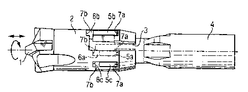
Fig. 1 shows a rock drill, in accordance with the invention; and
Fig. 2 shows a variant of the rock drill of Figure 1.
DESCRIPTION OF A SPECIFIC EMBODIMENT
Figure 1 shows a cross-sectional view of a rock drill comprising a potlike
drill
head (2) set with cutting edges (1 ) made of hard material, which runs on
peripheral
inner bearing surfaces 3 axially. The drill head (2) is form-lockingly
rotationally-fixed
and detachably connected with two driver blades 5a, 5b with a hollow drill
shaft 4 (only
partially represented), at the head-end radialfy tapering, and two bayonet-
type
connection slots 6a, 6b associated with the driver blades 5a, 5b, within which
the driver
blade 5a, 5b has limited axial movement within several millimeters.
Figure 2 shows a variant of the rock drill of Figure 1, having three radially
open
connection slots 6a, 6b, 6c, which are essentially peripherally off set by
120°, whereby
the driver blade 5a, 5b, 5c and three associated, axially open, bayonet-type,
radially
open connection slots 6a, 6b, 6c, are present, on the shaft-side, in the
counter-
rotational direction. The driver blade 5a and the connection slot 6a are shown
phantom, in the background of the drawing. The connection slot 6b forms two
axially
opposing undercuts 7a, 7b and differs in its length and width from the
connection slot
6c. The axial distance of the opposing undercuts 7a, 7b is smaller than the
doubled
axial length of the associated driver blade 5a.
Though the present invention was shown and described with references to the
preferred embodiments, such are merely illustrative of the present invention
and are not
to be construed as a limitation thereof, and various modifications of the
present
invention will be apparent to those skilled in the art. It is, therefore, not
intended that
NYI 5282836v1

CA 02413947 2002-12-11
the present invention be limited to the disclosed embodiments or details
thereof, and
the present invention includes all variations andlor alternative embodiments
within the
spirit.and scope of the present invention as defined by the appended claims.
rrm sze2ss6m

Dessin représentatif
Une figure unique qui représente un dessin illustrant l'invention.
États administratifs

2024-08-01 : Dans le cadre de la transition vers les Brevets de nouvelle génération (BNG), la base de données sur les brevets canadiens (BDBC) contient désormais un Historique d'événement plus détaillé, qui reproduit le Journal des événements de notre nouvelle solution interne.

Veuillez noter que les événements débutant par « Inactive : » se réfèrent à des événements qui ne sont plus utilisés dans notre nouvelle solution interne.

Pour une meilleure compréhension de l'état de la demande ou brevet qui figure sur cette page, la rubrique Mise en garde , et les descriptions de Brevet , Historique d'événement , Taxes périodiques et Historique des paiements devraient être consultées.

Historique d'événement

Description Date
Le délai pour l'annulation est expiré 2007-12-11
Lettre envoyée 2006-12-11
Accordé par délivrance 2006-08-01
Inactive : Page couverture publiée 2006-07-31
Inactive : Taxe finale reçue 2006-05-10
Préoctroi 2006-05-10
Un avis d'acceptation est envoyé 2006-04-13
Lettre envoyée 2006-04-13
Un avis d'acceptation est envoyé 2006-04-13
Inactive : Approuvée aux fins d'acceptation (AFA) 2006-03-30
Inactive : CIB de MCD 2006-03-12
Modification reçue - modification volontaire 2006-02-07
Inactive : Dem. de l'examinateur par.30(2) Règles 2005-12-01
Demande publiée (accessible au public) 2003-06-13
Inactive : Page couverture publiée 2003-06-12
Inactive : Regroupement d'agents 2003-05-30
Lettre envoyée 2003-04-08
Lettre envoyée 2003-04-03
Requête d'examen reçue 2003-03-17
Exigences pour une requête d'examen - jugée conforme 2003-03-17
Toutes les exigences pour l'examen - jugée conforme 2003-03-17
Inactive : Transfert individuel 2003-02-25
Inactive : CIB en 1re position 2003-02-20
Inactive : Lettre de courtoisie - Preuve 2003-02-04
Inactive : Certificat de dépôt - Sans RE (Anglais) 2003-01-29
Demande reçue - nationale ordinaire 2003-01-29

Historique d'abandonnement

Il n'y a pas d'historique d'abandonnement

Taxes périodiques

Le dernier paiement a été reçu le 2005-11-18

Avis : Si le paiement en totalité n'a pas été reçu au plus tard à la date indiquée, une taxe supplémentaire peut être imposée, soit une des taxes suivantes :

  • taxe de rétablissement ;
  • taxe pour paiement en souffrance ; ou
  • taxe additionnelle pour le renversement d'une péremption réputée.

Les taxes sur les brevets sont ajustées au 1er janvier de chaque année. Les montants ci-dessus sont les montants actuels s'ils sont reçus au plus tard le 31 décembre de l'année en cours.
Veuillez vous référer à la page web des taxes sur les brevets de l'OPIC pour voir tous les montants actuels des taxes.

Historique des taxes

Type de taxes Anniversaire Échéance Date payée
Taxe pour le dépôt - générale 2002-12-11
Enregistrement d'un document 2003-02-25
Requête d'examen - générale 2003-03-17
TM (demande, 2e anniv.) - générale 02 2004-12-13 2004-11-29
TM (demande, 3e anniv.) - générale 03 2005-12-12 2005-11-18
Taxe finale - générale 2006-05-10
Titulaires au dossier

Les titulaires actuels et antérieures au dossier sont affichés en ordre alphabétique.

Titulaires actuels au dossier
HILTI AKTIENGESELLSCHAFT
Titulaires antérieures au dossier
MARTIN DR. RICHTER
STEFAN GOTZFRIED
UDO HAUPTMANN
WERNER KLEINE
Les propriétaires antérieurs qui ne figurent pas dans la liste des « Propriétaires au dossier » apparaîtront dans d'autres documents au dossier.
Documents

Pour visionner les fichiers sélectionnés, entrer le code reCAPTCHA :


Pour visualiser une image, cliquer sur un lien dans la colonne description du document. Pour télécharger l'image (les images), cliquer l'une ou plusieurs cases à cocher dans la première colonne et ensuite cliquer sur le bouton "Télécharger sélection en format PDF (archive Zip)" ou le bouton "Télécharger sélection (en un fichier PDF fusionné)".

Liste des documents de brevet publiés et non publiés sur la BDBC .

Si vous avez des difficultés à accéder au contenu, veuillez communiquer avec le Centre de services à la clientèle au 1-866-997-1936, ou envoyer un courriel au Centre de service à la clientèle de l'OPIC.


Description du
Document 
Date
(aaaa-mm-jj) 
Nombre de pages   Taille de l'image (Ko) 
Abrégé 2002-12-10 1 14
Description 2002-12-10 5 185
Revendications 2002-12-10 2 47
Dessins 2002-12-10 1 37
Dessin représentatif 2003-02-20 1 10
Revendications 2006-02-06 2 32
Certificat de dépôt (anglais) 2003-01-28 1 160
Accusé de réception de la requête d'examen 2003-04-07 1 185
Courtoisie - Certificat d'enregistrement (document(s) connexe(s)) 2003-04-02 1 130
Rappel de taxe de maintien due 2004-08-11 1 111
Avis du commissaire - Demande jugée acceptable 2006-04-12 1 162
Avis concernant la taxe de maintien 2007-01-21 1 171
Correspondance 2003-01-28 1 24
Taxes 2004-11-28 1 30
Taxes 2005-11-17 1 31
Correspondance 2006-05-09 1 29