Note : Les descriptions sont présentées dans la langue officielle dans laquelle elles ont été soumises.
CA 02414113 2003-O1-09
WO 02/03804 PCT/USO1/41010
Conveyor Oven
Field of the Invention
The present invention relates to ovens and, more particularly, to ovens
employing impingement airflow methods.
Background of the Invention
Examples of forced air or impingement ovens that use conveyors can be
found in the prior art. A dual conveyor oven is disclosed by Smith in U. S.
Pat. No.
4,474,498 where dual sets of air manifolds are utilized to provide heated air
to two
conveyors in an oven cabinet. An impeller arrangement is disclosed that draws
return air from the front and exhausts re-heated air vertically into adjacent
air
manifolds. While effective, this arrangement does not provide a dual conveyor
oven
with a low profile nor does it provide for the easy and quick removal of the
conveyors ~-ia a removable front panel. Furthermore, the conveyor speed cannot
be
individually controlled.
Another dual conveyor oven is disclosed by Wolfe in U. S. Pat. No.
5,832,812, which employs two, side-fed centrifugal fans mounted on a common
shaft
having an axis parallel to the direction of conveyor travel. This design has
inherent
problems in shaft vibration during operation due the shaft's length and the
fans are
difficult to remove for service and cleaning. Furthermore, the style of
centrifugal fan
in this design creates an airflow pattern that is much more difficult to
balance than
alternative fan designs. This design also requires the oven to have a deep
"footprint"
that is not always practical in restaurants. Finally, the burner tube design
and
location does not provide uniform return air re-heating before air enters the
side-fed
centrifugal fans along with difficult service and replacement of the burner
tube, fans
and fan housings.
A single conveyor, stackable conveyor oven is disclosed by Bruno in U. S.
Pat. No. 5,277,105 that utilizes two, rear-fed, backward-inclined blade
centrifugal
fans. The '105 patent discloses a front-mounted burner tube that is mounted
perpendicular to the direction of conveyor travel. This burner tube
orientation
provides uneven and non-uniform heat patterns within the oven cabinet. No
CA 02414113 2003-O1-09
WO 02/03804 PCT/USO1/41010
provision is made to remove the conveyors quickly and easily. The conveyor
wire
belt must be removed and the conveyor folded for removal. Each centrifugal fan
is
driven by an individual electric motor that increases service cost over the
life of the
unit. The front mounted oven controls disclosed in this patent require
dedicated
cooling fans to prevent damage from excessive heat build-up that again
increase
service costs. Finally, this design requires a deep "footprint" that is not
always
practical in restaurants.
Finally, the stackable conveyor oven disclosed by Crisp in U. S. Pat. No.
5,025,775 utilizes two axial fans with separate motors mounted in the fan box
to
provide heated air movement. Only three ovens may be stacked to provide only
three conveyor levels. As tvvo motors are required per oven, service costs are
increased over the unit's service life. Furthermore, no quick and easy
conveyor
removal method is disclosed. Lastly, the controls are mounted on the side of
the
bake chamber. In a double or triple stack configuration, heat from the lower
ovens
s
rises and damages the sensitive electrical controls again increasing lifetime
ser~~ice
costs.
While the prior art yields a number of conveyor oven designs having various
axial and centrifugal fan air manifold arrangements, none of these teach the
novel
features and associated benefits found in the present invention.
Summary of the Invention
The shortcomings inherent in the prior art are overcome by the present
invention, which comprises a low profile, dual conveyor impingement oven
having a
bake chamber, two conveyor assemblies, a fan box with two centrifugal fans
with
axes mounted perpendicular to the direction of conveyor travel, two hot air
distribution manifolds, six side-mounted, return air ducts and a drive end
control
unit. Other embodiments include a single conveyor oven with two centrifugal
fans
or a single conveyor oven with a-shorter bake chamber that requires only a
single
centrifugal fan.
2
CA 02414113 2003-O1-09
WO 02/03804 PCT/USO1/41010
Each conveyor is positioned horizontally in the bake chamber to transport
food products from one end to the other. Each conveyor has its own speed
control to
allow two separate bake times in a single oven. The bake chamber utilizes a
cantilever design that allows easy and quick conveyor, air finger and return
air duct
removal from the front of the oven. When the front panel is removed, complete
access is provided for cleaning or maintenance. The bake chamber is mounted to
the
fan box and may be removed if required for oven installation or maintenance.
The fan box contains two, backward-inclined blade, rear-fed centrifugal fans
spaced along the length of the bake chamber. The rotational axis of each fan
is
perpendicular to the direction of conveyor travel. One electric motor mounted
in the
1 S drive end provides power to both fans.
A burner tube is mounted at the rear of the fan box. The burner tube has
openings to allow heated gas to exit the tube and heat the air being drawn
into each
fan. The design of the burner tube and the fact that each fan has only a
single
opening where heated air is drawn provides a much more uniform heat pattern
when
compared to the prior art.
Heated air is drawn into each fan's inlet, which is operating at low pressure.
Centrifugal force is imparted on the air and it is pressurized as it moves
outward into
each fan's housing. The fan housing operates at a uniform, high pressure. The
pressurized air is then directed into the three air fingers that are connected
to the fan
housing. The air fingers are adapted to distribute the heated air uniformly in
the
bake chamber on to food products being transported on either the top or bottom
conveyor. This novel use of a backward-inclined blade centrifugal fan combined
with a fan housing and three hot air fingers provides improved air flow that
results in
more uniform air distribution to the top and bottom of both conveyors and a
uniform
heat pattern within the bake chamber.
The bake chamber contains six return air ducts that channel spent cooking air
back into the fan box for re-heating. These return air ducts greatly reduce
the
CA 02414113 2003-O1-09
WO 02/03804 PCT/USO1/41010
amount of spent air that escapes through the conveyor openings thereby
increasing
operating efficiency.
Appropriate control means are located in the drive end. These controls
provide electricity to the main fan motor, the conveyor motors, the combustion
air
motor and control power to the temperature and conveyor time controls and the
gas
valves.
Due to the invention's low-profile design, it is possible to stack two units
and
provide a total of four conveyor levels. Furthermore, the novel use of
centrifugal
fans whose axis of rotation is perpendicular to the direction of conveyor
travel allows
the ovens front to back dimension or depth to be minimized. Therefore, the
present
invention provides the maximum baking capacity in the smallest "footprint." In
addition to maximizing cooking capacity, menu flexibility is also increased
with the
ability to cook on four separate conveyors with each operating at a separate
speed.
Yet another advantage of the present invention is the ability to quickly and
easily remove the conveyors, air fingers and return air ducts for cleaning or
service.
The removable front panel provides instant access to all components located
inside
the bake chamber. The side mounted oven controls are located away from the
source
of heat that will extend their service life. Since all oven controls and
motors are
located in the drive end, time required to replace any of these components is
minimized.
These and other advantages of the present invention are provided below.
Description of the Drawings
The following detailed description refers to the attached drawings in which:
FIG. 1 is a front perspective view of the oven of the present invention with
portions
cut away for clarity;
FIG. 2 is a sectional view taken along line 2 - 2 of FIG. 3;
FIG. 3 is a front sectional view taken along line 3 - 3 of FIG. 5;
FIG. 4 is an elevation view as seen from the rear of the oven;
4
CA 02414113 2003-O1-09
WO 02/03804 PCT/USO1/41010
FIG. 5 is an overhead sectional view taken along line 5 - 5 of FIG. 3;
FIG. 6 is a side sectional view taken along line 6 - 6 of FIG. 3;
FIG. 7 is a side sectional view taken along line 7 - 7 of FIG. 4;
FIG. 8 is a side sectional view taken along line 8 - 8 of FIG. 4;
FIG. 9 is a front elevation view of a stack of dual conveyor ovens;
FIG. 10 is a front elevation view of another embodiment showing a stack of
single
conveyor ovens;
FIG. 11 is an overhead sectional view of another embodiment using only a
single
centrifugal fan;
FIG. 12 is a perspective view of another embodiment using a single centrifugal
fan
and two conveyor levels;
FIG. 13 is a perspective view of another embodiment using two centrifugal fans
and
one conveyor level;
FIG. 14 is a perspective view of another embodiment using a single centrifugal
and
one conveyor level; and
FIG. 1 S is a sectional view of an embodiment using an axial fan taken along
line 2 -
2 of FIG. 3.
Detailed Description of the Preferred Embodiment
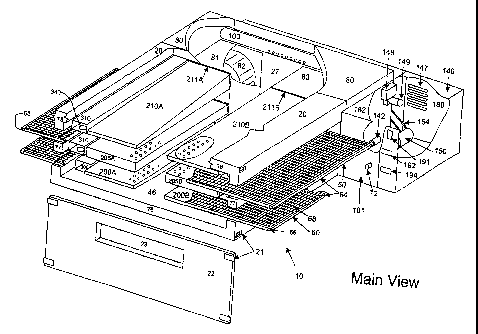
The oven 10 of the present invention is shown in FIG. 1. Oven 10 generally
includes a bake chamber 20 having front, back, right and left sides; conveyor
assemblies 50 and 60; fan box 80, and drive end unit 140.
FIG. 1 shows bake chamber 20 further including a front panel 22, bottom
bake chamber 76, middle bake chambers 77, top bake chamber 78. Front panel 22
is
held in place by four latch assemblies 21 and is therefore easily removable.
Front
panel 22 also includes an opening or aperture 23 that allows a product to be
placed
on the top conveyor at the bake chamber's midpoint.
The bake chamber top 78 and bake chamber middle 77 sections form two top
bake chamber openings 51 (FIG. 3). The bake chamber middle supports 77 provide
support to conveyor SO when installed. The bake chamber middle sections 77 and
5
CA 02414113 2006-05-10
WO 02/0380:1 PCT/USOi/~1010
bake chamber bottom 76 form two bottom bake chamber openings 61 (Fig. 3). The
bake chamber bottom 76 provides support to conveyor 60 when installed.
All bake chamber sections are preferably made from thin stainless steel and
are hollow. The preferred embodiment utilizes insulating materials within
these
hollow components. As the oven may be stacked, all bake chamber components
must be lightweight yet strong.
Con veyor Assembly Details
As shown in FIGS. l and 3, bake chamber 20 includes an upper conveyor
assembly 50 and a lower conveyor assembly 60 that are interchangeable in the
preferred embodiment. Each conveyor assembly 50, 60 comprises a frame 64 that
in
turn supports two rotating shafts: drive shaft 66 and idle shaft 65. Wire mesh
belt
68 defines a continuous loop around shafts 65 and 66 as a direction of
movement
thereof. Frame 64 carries a rigid wire frame (not shown) installed between
shafts 65
and 66 that further support the wire mesh belt 68.
1S Each conveyor drive shaft has a male, cogged coupling that couples with a
female cogged coupling 72 (FIG. 12). The female cogged coupling 72 is
connected
to a separately controlled conveyor drive motor 142 and 144 described
belo~cs~.
Cogged couplings are adapted for easy engagement and disengagement to
facilitate conveyor 50 and 60 removal and reinstallation.
~r-Heating, Distribution and Return Systerv
The oven of the present invention as shown in FTGS.I and 3 has an air
heating and delivery/circulation system that includes a fan box 80, burner
assembly
148, burner tube I00, lower return air ducts 300, top and middle return air
ducts 310,
central return air opening 27, backward-inclined centrifugal drive end fan 84,
backward-inclined centrifugal idle end fan 82, drive end fan housing 83, idle
end fan
housing 81 and the following plenums for evenly distributing hot air: upper
fingers
21 OA and 210B, middle fingers 205A and 205B and lower fingers 200A and 200B.
6
CA 02414113 2003-O1-09
WO 02/03804 PCT/USO1/41010
Fan box 80 is an air-tight chamber that normally operates at a negative
pressure and thus draws spent cooking~air in through the return air ducts 300
and 310
(FIGS. 1, 3). The return air is then re-heated in the fan box 80 by burner
tube 100
before entering the centrifugal fans 82 and 84. Fans 82 pressurize re-heated
air and
84 located in their respective fan housings 81 and 83 (FIG. 5). Centrifugal
fans 82
and 84 expel a substantially uniform pressure, non-swirling column of air in a
forward direction toward air fingers 210A, 210B, 205A, 205B, 200A and 200B.
FIG. 6 illustrates heated return air entering fan 82 and then being discharged
towards the air fingers. The elliptical air guides 30 facilitate air movement
by
reducing resistance due to their elliptical shape as heated air passes through
the fan
housing and enters the air fingers.
The preferred embodiment incorporates two identical fan housing
arrangements with the central return air opening 27 located between them (FIG.
5).
A detailed description of air distribution via air fingers 210A, 210B, 205A,
205B,
200A and 200B follows.
HotAirManifold~F'inger)Details
FIGS. 1, 2 and 8 illustrate how the idle end hot air manifolds or forgers
attach
to the idle end fan housing 81. Lower, middle and upper fingers 200A, 205A, 21
OA
slide into corresponding collar joints 201A, 206A, 21 lA that are fixed to the
idle end
fan housing. FIG. 7 illustrates collar joints 201B, 206B, 211B for the drive
end
fingers 200B, 205B and 210B. All fingers are generally tapered, hollow
stainless
steel enclosures that are open at one end where they are joined with their
corresponding collar joint.
While the back of each finger is supported b~T the collar joint, the front of
. each finger rests on forger support angles: top finger support angle 90,
middle finger
support angle 91 and lower finger support angle 92. All finger support angles
are
shown in FIG.2, but are not shown in FIG.1 for clarity.
The following fingers are interchangeable: Lower finger 200A and 200B,
middle finger 205A and 205B and upper finger 210A and 210B. Therefore, only
the
idle end manifolds will be described in detail. FIG. 6 shows lower manifold
200A
7
CA 02414113 2003-O1-09
WO 02/03804 PCT/USO1/41010
comprised of a finger body 200B and an air plate 200C which has a pattern of
air
holes 203. Middle finger 205A has a lower air plate 207 with air holes 227, an
upper
air plate 208 with air holes 228 and an internal baffle 232. Internal baffle
232 has a
series of holes 234 that allow about 1/3 of the air flow to this finger to
travel
downward and out through air plate 207. The upper finger 210A is comprised of
a
finger body 210B and an air plate 210C with air hole pattern 213.
In the preferred embodiment, internal blocking plates are attached to finger
air plates as required to adapt the airflow to cook particular types of food
product.
The overall dimension of the forgers along with the internal blocking plates
have
been adapted to provide about twice the air flow directed up into the
conveyors when
compared to the air flow directed down. It should be apparent to those skilled
in the
art that other manifold configurations could be used to achieve different air
distribution characteristics.
Return Air Duct Details
The oven of the preferred embodiment has a means for returning spent
cooking air from the bake chamber 20 back to the fan box 80. The use of these
return air ducts reduces the amount of spent cooking air that escapes through
the
bake chamber opening 51 for the top conveyor 50 and the bake chamber opening
61
for the bottom conveyor 60.
FIGS. 1 and 3 illustrate six separate return air ducts: two identical lower
return air ducts 300 and four identical top and middle return air ducts 310.
FIG. 1
shows the return air ducts at the idle end of the oven installed. Rear wall 26
at the
back of the bake chamber 20 has openings to accept the two top return air
ducts 310
and the two middle return air ducts 310. Lower return air ducts 300 are placed
on
the floor of the bake chamber bottom 46. The front of all return air ducts are
supported by the finger support angles (top finger support angle 90, middle
finger
support angle 91 and Iower finger support angle 92(FIG. 2)) in the same manner
as
the front of the hot air manifolds (fingers) are supported.
8
CA 02414113 2003-O1-09
WO 02/03804 PCT/USO1/41010
As illustrated in FIG. 2, in the preferred embodiment, each of the return air
ducts are rectangular in shape and made from thin stainless steel sheet metal
and are
open at each end. Top and middle return air ducts 310 have openings 340 (FIG.
1) in
the bottom side while the lower return air duct 300 has no openings. The
central
return air opening 27, which is only present on embodiments with two fan
assemblies, is part of the return air system that improves oven performance.
Centrifugal Fan Drive and Fan HousingArrangement
The preferred embodiment of the present invention utilizes two rear-fed,
centrifugal fan assemblies to provide hot air circulation within the bake
chamber 20
and fan box 80. It should be noted that axial fans may be substituted to
provide
similar results. FIG. 5 shows an overhead sectional view of the preferred
embodiment while FIG. 4 illustrates the rear of the fan box.
Drive end fan 84 (FIG. 4) has a permanently attached drive shaft 86 that is
supported by two bearings 201. These bearings are mounted to a specially
designed
bracket 204 along with pulleys 202 and 203, and the entire assembly is bolted
to the
fan box rear panel 141. Heat slinger 200 is placed on shaft 86 to cool the
bearings
during operation.
Idle end fan 82 (FIG. 4) has a permanently attached drive shaft 85 that is
supported by two bearings 201. These bearings are mounted to a specially
designed
bracket 206 along with pulley 205 and the entire assembly is bolted to the fan
box
rear panel I41. Heat slinger 200 is placed on shaft 85 to cool the bearings
during
operation.
Rotational energy is provided to both centrifugal fans 82 and 84 by a single
electric motor 150 using a pulley 152 and drive belt 154 (FIG. 4). Again,
axial fans
or the like may be substituted for centrifugal fans. Belt 154 rotates fan 84,
and fan
82 also rotates as another belt 160 is driven off of drive end fan shaft 86
and pulley
202. Heat stinger 200 is placed on the motor 150 output shaft to provide air
circulation within the drive end to cool sensitive electrical components. Belt
154 is
tightened by moving motor 150 away from the fan box and belt 160 is tightened
by
moving idler pulley 161 vertically on bracket 204. An alternative embodiment
for
9
CA 02414113 2003-O1-09
WO 02/03804 PCT/USO1/41010
the fan drive means would be to have a separate motor drive each fan. However,
the
preferred embodiment of using a single motor to drive both fans reduces the
number
of moving parts in the oven and thus reduces the opportunity for future
maintenance.
This novel design provides several advantages over the prior art. The first is
an elimination of two fan drive motors per oven cavity. A single motor driving
both
fans will reduce service costs over the unit's service life. Second, the fans
are
mounted on separate drive shafts which allows easy removal and cleaning versus
fans that are mounted on a common shaft. The heat stinger installed on the
drive
motor eliminates the need for separate electric cooling fans to circulate air
within the
control panel to cool sensitive electrical components. Again, a service
expense
reduction will be enjoyed by the end user.
Drive End UnitDetails
FIGS. 1 and 4 show the drive end unit 140 that includes a welded steel
framel79, a rear panel 180, front panel 181 and top access panel 182. Enclosed
in
the drive end unit 140 is main blower motor 150, burner assembly 148, conveyor
motors 142 and 144 with respective conveyor speed controllers 192 and 194 and
bake chamber temperature control 191. The bottom of the drive end unit 140 is
generally open to allow air to enter the compartment while louvers 147 in the
rear
panel 180 allow air to circulate freely. Heat stinger 200 provides air
movement
throughout the compartment when the main blower motor 150 is in operation.
Combustion air motor 149 provides forced air to burner 148 where it is mixed
with gas and combusted. The combustion air motor 149 also has a manual means
for
controlling the air/gas mixture that in turns controls combustion efficiency.
Combusted air is forced down burner tube 100 that travels the length of fan
box 80 to
re-heat spent air from the bake chamber.
Conveyor motors 144 and 142 provide rotational energy to conveyor
assemblies 50 and 60 (FIGS l, 4). Female cogged couplings 72 are attached to
drive
motors 144 and 142 to provide easy installation and removal of the conveyor
assemblies. Each conveyor motor 144 and 142 has a separate speed control 194
and
CA 02414113 2003-O1-09
WO 02/03804 PCT/USO1/41010
192 that may be turned on or off independent of the other control. Each
conveyor
motor 144 and 142 may be rotated either clockwise or counter clockwise.
Other Embodiments
FIG. 9 illustrates the stacking of two, dual conveyor ovens of the present
invention, and FIG. 10 illustrates the stacking of two, single conveyor ovens
of the
present invention.
FIGS. 11, 12, 13 and 14 illustrate alternative embodiments according to the
present invention. These embodiments feature the same novel airflow method,
drive
end configuration and burner means configuration while utilizing different
combinations of single versus dual centrifugal fans, and single versus dual
conveyor
configurations.
FIG. 15 illustrates that an aa:ial fan 82 can be utilized as the heated air
delivery means.
Finally, although the preferred embodiment employs a gas-fired burner
means, an electric-powered heating element could also be used to generate heat
and
provide the same heat transfer results.
Operation
In operation, the food product (i.e., pizza. bread, breadsticks, casseroles,
etc.)
is placed on the rotating conveyors) of the present invention and processed
through
the device. Using the controls for the burner and conveyor speed, the operator
can
set the cooking temperature to bet<veen about 250 °F to about 600
°F, and the
cooking time to between about 2 minutes to about 20 minutes.
The skilled reader being aware of the versatility of this preferred embodiment
may envision many modifications and variations that are not limited to only
those
listed above. Accordingly, the reader should understand that these
modifications and
variations, and the equivalents thereof, are within the spirit and scope of
this
invention as defined by the following claims.
11