Note : Les descriptions sont présentées dans la langue officielle dans laquelle elles ont été soumises.
CA 02414363 2002-12-31
WO 02/05445 PCT/KRO1/01169
-1-
METHOD AND APPARATUS FOR FLEXIBLE DATA RATE MATCHING
BY SYMBOL INSERTION FOR A DATA COMMUNICATION SYSTEM
BACKGROUND OF THE INVENTION
1. Field of the Invention
The present invention relates generally to a data communication system, and in
particular, to a method and apparatus for matching a frame having a variable
number of
code symbols according to a variable data rate, to an interleaves size prior
to
transmission.
2. Description of the Related Art
Convolutional encoding or linear block encoding using a single decoder is a
general encoding method in a mobile communication system such as a satellite
system,
ISDN (Integrated Service Digital Network), a digital cellular system, a W-CDMA
(Wide
band Code Division Multiple Access) system, UMTS (Universal Mobile
Telecommunications System), and 1MT (International Mobile Telecommunications)-
2000. Code symbols resulting from those channel encoding are generally
interleaved by
a channel interleaves.
A typical channel interleaves interleaves a frame having as many code symbols
30
as an interleaves size per frame. On the other hand, the more recent channel
interleaves
performs FDRT (Flexible Data Rate Transmission) interleaving. That is, it
interleaves a
frame having code symbols different from an interleaves size per frame.
FIG. 1 illustrates a non FDRT-based channel interleaves for interleaving a
frame having as many code symbols as an interleaves size. Referring to FIG. 1,
if a data
rate is fixed, the number L of code symbols per unit frame input to a channel
interleaves
100 is always equal to an interleaves size N in a non-FDRT scheme. For
example, there
are diverse transmission channels including RC1, RC2, RC3, RC4, RCS, RC6, RC7,
RCB, and RC9 according to the radio configuration (RC) of an I1VIT-2000 and
they differ
in data frame size, code rate, and interleaving. A transmission channel
transmits at a
predetermined data rate according to its characteristics.
FIG. 2 illustrates an example of a code symbol frame transmitted according to
the non-FDRT scheme. Referring to FIG. 2, when the data rate of a physical
channel is
set at that of RC3, that is, 19.2kbps, N is 1536. A 20ms frame at 19.2kbps
contains 384
bits per second and an R=1/4 code encoder outputs 1536 bits per second. If a
user
CA 02414363 2002-12-31
WO 02/05445 PCT/KRO1/01169
_2_
intends to transmit a frame at 20kbps, the data rate of the physical channel
is set at
38.4kbps, a minimum data rate higher than 20kbps by initial negotiation
between a base
station and a mobile station. Then, N is 3072(=2x1536):
As the data rate increases from 20kbps to 38.4kbps, a higher layer writes null
data in the remaining area of a channel interleaver (not shown) after input
data symbols
of 20kbpsx20msec are filled. In other words, 47.92%(=38.4-20/3.4) of the
output of
the channel interleaver of size N is transmitted as null data. Consequently,
47.92%
energy is dissipated in the aspect of received symbol energy. The energy loss
occurs
because there is no way to process null data in a physical layer in the non-
FDRT scheme.
Even if the null data is processed by symbol repetition, symbol combination is
not
available to a forward supplemental channel (F-SCH). Moreover since null data
varies
with the data rate of input code symbols, the higher layer should notify the
base station
and the mobile station of variations beforehand. In reality, energy must be
recovered
with respect to the null data before channel decoding and an Ll/L2 higher
layer
processes only decoded information symbols after channel decoding. As a
result,
decoding performance is deteriorated.
FDRT was proposed to improve performance, overcoming the problem of non-
FDRT. FDRT is a data rate matching scheme to increase coded data transmission
efficiency and improve system performance in a multiple access and multiple
channel
system using channel encoding. The idea of FDRT is based on the premise that
the
channel code used is a convolutional code, a linear code, or a concatenated
code using a
convolutional code. The 3GPP (3rd Generation Project Partnership 2) attracting
much
interest has settled with FDRT tentatively as the standard of the air
interface and FDRT
is being realized in real situations.
However, the conventional IS-2000 FDRT and the current IS-2000 FDRT for a
convolutional code or a linear block code have the following problems.
(1) The conventional FDRT scheme requires uniform puncturing if possible
because it can be supposed that error sensitivity is almost uniform across all
code
symbols in a frame output from a convolutional encoder or a lineax block
encoder. The
supposition is not valid to the current IS-2000 FDRT.
(2) It was considered in the conventional IS-2000 FDRT that the use of a
repetition scheme from the perspective of symbol repetition has little
influence on a
puncturing pattern. Yet, this symbol repetition must be considered on the
level of
CA 02414363 2002-12-31
WO 02/05445 PCT/KRO1/01169
-3-
symbol puncturing. That is, uniform symbol repetition should be achieved on
the
supposition that error sensitivity is almost uniform across all code symbols
in a frame
output from an encoder, for FDRT with optimum performance. However, this
supposition is not valid to the current IS-2000 FDRT.
(3) Although symbol repetition is enough, symbol puncturing follows the
symbol repetition in the conventional IS-2000 FDRT. Therefore, implementation
complexity results.
The IS-2000 FDRT for an error correction code such as a turbo code also has
the problem described below.
As stated before, according to the FDRT for a convolutional code or a linear
block code, uniform puncturing is required if possible on the supposition that
each frame
output from an encoder has almost uniform error sensitivity in all the code
symbols. In
the case of a turbo code, on the other hand, error sensitivity is different in
code symbols
of each frame (codeword) output from an encoder. In other words, code symbols
from a
turbo encoder can be grouped according to their error sensitivities. Also in
the case of
the turbo code, there is a need for an FDRT scheme that ensures uniform
puncturing or
repetition for all symbols in each code symbol group. Yet, the current IS-2000
FDRT
has limitations in this context.
SUMMARY OF THE INVENTION
It is, therefore, an object of the present invention to provide a flexible
data rate
matching method and apparatus, which ensure optimum performance when a
convolutional code, a turbo code, and a linear block code are used
individually or in
combination in a data communication system.
It is another object of the present invention to provide a flexible data rate
matching method and apparatus which are simple and flexible at a variable data
rate by
controlling initial values in a data communication system using a
convolutional code, a
turbo code, or a linear block code.
It is a further object of the present invention to provide a flexible data
rate
matching method and apparatus for a data communication system.
The foregoing and other objects of the present invention can be achieved by
CA 02414363 2002-12-31
WO 02/05445 PCT/KRO1/01169
-4-
providing a flexible data rate matching method and apparatus by symbol
repetition in a
data communication system. To generate a sequence of N symbols from a sequence
of L
code symbols less than the N symbols in a system having an encoder for
generating the
sequence of L code symbols and a channel interleaves for receiving the
sequence of N
symbols, symbols at generally equidistant (N-L) positions are detected among
the L
code symbols and the detected symbols are sequentially inserted before or
after the
detected symbols by repetition.
BRIEF DESCRIPTION OF THE DRAWINGS
The above and other objects, features and advantages of the present invention
will become more apparent from the following detailed description when taken
in
conjunction with the accompanying drawings in which:
FIG. 1 illustrates a typical non-FDRT-based channel interleaves;
FIG. 2 illustrates an example of a code symbol frame transmitted according to
non-FDRT;
FIG. 3 is a block diagram of an FDRT device that performs symbol repetition &
puncturing according to the IS-2000 specifications;
FIG. 4 is a block diagram of a transmitting device in an FDRT scheme
according to an embodiment of the present invention; '
FIGS. 5A, SB, and SC illustrate examples of symbol outputs from an FDRT
device shown in FIG. 4;
FIG. 6 is a flowchart illustrating an FDRT operation according to the
embodiment of the present invention;
FIG. 7 is a detailed block diagram of the FDRT device according to the
embodiment of the present invention;
FIG. 8 is a block diagram of an FDRT device according to another embodiment
of the present invention;
FIG. 9 is a view for describing a problem possibly encountered in FDRT-
processing code symbols output as one sequence from a turbo encoder;
FIG. 10 illustrates examples of symbols generated with an initial offset
concept
introduced according to a third embodiment of the present invention;
FIG. 11 is a flowchart illustrating an initial offset determination procedure
for
determining the first symbol to be repeated in a frame after encoding in an
encoder that
outputs code symbols in a sequence according to the third embodiment of the
present
invention; and
FIG. 12 is another flowchart illustrating an initial offset determination
procedure for determining the first symbol to be repeated in a frame after
encoding in an
CA 02414363 2002-12-31
WO 02/05445 PCT/KRO1/01169
-5-
encoder that outputs code symbols in a sequence according to the third
embodiment of
the present invention.
DETAILED DESCRIPTION OF THE PREFERRED EMBODIMENTS
Preferred embodiments of the present invention will be described hereinbelow
with reference to the accompanying drawings. In the following description,
well-known
functions or, constructions are not described in detail since they would
obscure the
invention in unnecessary detail.
Before a detailed description of the present invention, an FDRT scheme
performing symbol repetition & puncturing as provided by the IS-2000
specifications
will be described below.
Refernng to FIG. 3, since during the input of L code symbols from an encoder
200, an FDRT block 210 outputs N code symbols equal to or greater than the L
code
symbols, the input symbols are subject to symbol repetition. Therefore, a
symbol
punctures 214 is used to match the repeated code symbols to the number of
output
symbols, the size N, of an interleaves 220. According to the above FDRT
scheme, code
symbols are repeated M times in a repeater 212 and the repeated code symbols
are
punctured in the symbol punctures 214 to match the code symbols to the
interleaves size
N.
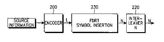
Embodiment 1
A novel FDRT scheme according to an embodiment of the present invention
inserts (N-L) symbols among L symbols and outputs N symbols finally, as
compared to
the conventional IS-2000 FDRT scheme where symbol puncturing is performed to
delete
(LM-N) symbols from LM symbols after M symbol repetitions. A transmitting
device
according to the novel FDRT scheme is illustrated in FIG. 4.
Referring to FIG. 4, an encoder 200 outputs a code sequence having L code
symbols by encoding source information. An FDRT device 230 inserts (N-L)
symbols
among the L code symbols and outputs N symbols. Specifically, the FDRT device
230
detects generally equidistant (N-L) symbol positions among the L code symbols
and
sequentially inserts the (N-L) symbols before or a$er the code symbols at the
detected
positions. An interleaves 220 interleaves the N symbols received from the FDRT
device
230. As shown in FIG. 4, the FDRT scheme according to the embodiment of the
present
invention is very simple because M times symbol repetition as illustrated in
FIG. 3 is
CA 02414363 2002-12-31
WO 02/05445 PCT/KRO1/01169
-6-
omitted.
Now, an algorithm run in the FDRT device 230 will be described in detail.
According to the FDRT algorithm according to the embodiment of the present
invention,
(N-L) code symbols are inserted among L code symbols without symbol repetition
accompanied by puncturing. For example, if a data rate is l7kbps, a frame is
20msec in
duration, a code rate R is 1/4, and the data rate of a channel to be
transmitted is 19.2kbps,
the FDRT device 230 inserts [(19.2-17)x20x4] symbols among the L symbols.
Since
optimum FDRT is characterized by almost uniform error sensitivity across all
symbols in
one frame (codeword) output from an encoder, the FDRT device 230 must perform
uniform symbol insertion in one frame if possible. Once the interleaver size N
and the
number L of input code symbols are given, the number of inserted symbols is
calculated.
After parameters, listed in Table 1, required for the FDRT algorithm
are.determined, a
symbol insertion pattern (or a symbol repetition pattern) will be determined.
It is to be
noted here that symbol insertion and symbol repetition are used in the same
meaning.
(Table 1)
ParameterDefinition
s
Nis=N-L Number of inserted symbols (because N>_L, Nis is
always a positive
number)
L Number of code symbols input to FDRT block
N Number of symbols output from FDRT block
Eacc Error accumulation value
(Ia, Variable determining first repeated symbol position
Ib) in frame (Ib is an
integer satisfying lSIb<_Ia)
In Table 1, L is the number of code symbols input to the FDRT device 230 after
encoding in the encoder 200 and N is the size of the interleaver 220, the
number of code
symbols output from the FDRT device 230 after data rate matching. Nis is the
number
of inserted symbols in the FDRT device 230. Eacc is a value obtained by
sequentially
decreasing a predetermined initial value by a predetermined decrement. In the
embodiment of the present invention, Eacc is generated for each symbol in a
frame and
compared with 0. If Eacc is less than or equal to 0, the symbol is repeated.
In this sense
Eacc is called an error accumulation value and the initial value is called an
initial error
accumulation value. The initial value can be (IaxNis).
(Table 2)
CA 02414363 2002-12-31
WO 02/05445 PCT/KRO1/01169
_7_
Eacc=Ib*L
M=1
do while mL
Eacc=Eacc-Ia*Nis;
do while Eacc<-0
repeat mth symbol
Eacc=Eacc+Ia*L
end do
m=m+1
end do
Table 2 is the FDRT algorithm according to the embodiment of the present
invention. "repeat mth symbol" means that an mth symbol is repeated. If Eacc
<_ 0, the
mth symbol repetition continues in a "do while" loop until Eacc > 0. When the
algorithm is completely run, that is, when the "while" loop is performed until
m=L, a
total of N symbols are generated. The N symbols are output from the FDRT
device 230
by inserting (N-L) symbols among L input code symbols. The FDRT algorithm of
Table 2 will be described in more detail later referring to FIG. 6.
Meanwhile, the algorithm of Table 2 is also applicable to VDRT (Variable Data
Rate Transmission) using an arbitrary value M (repeating times). Since the
FDRT
algorithm selects repeated symbol positions, consecutive puncturing that
discards
particular code symbols does not occur unlike the conventional FDRT scheme
performing symbol repetition & puncturing. Accordingly, the performance
deterioration
caused by the consecutive puncturing does not occur either.
If Eacc, 0, Ia*Nis, and Ia*L are defined as an error accumulation value, a
threshold, a decrement, and an increment, respectively, the algorithm is
performed in the
following steps of (a) setting Eacc for the first symbols among L code
symbols; (b)
comparing Eacc with 0; (c) updating Eacc by Eacc+ Ia*L if Eacc is less than 0
and
returning to step (b); (d) updating Eacc by Eacc- Ia*Nis if Eacc is greater
than 0 and
returning to step (b); and (e) ending the procedure if a sequence of N symbols
is
generated from the L code symbols during steps (c) or (d). While it is
preferable to set
the threshold, the decrement, and the increment to 0, Ia*Nis, and Ia*L
respectively, they
can be set to appropriate empirical values.
Application cases of the FDRT algorithm according to the embodiment of the
present invention will be presented below. In Case 1, M=1, that is, no symbol
repetition
CA 02414363 2002-12-31
WO 02/05445 PCT/KRO1/01169
_g_
is given. In Case 2, M=2. A code sequence is repeated once and thus two same
code
sequences are generated. In Case 3, M=3. A code sequence is repeated twice and
three
same code sequences are generated. In all cases, (Ia, Ib)=(2, 1)
(Case 1}
If L=5 and N=5, Nis=N-L=5-5=0. This case requires no symbol repetition.
Table 3 shows the case where a symbol repetition pattern is given as c1, c2,
c3, c4, c5
for code symbol positions m=l, 2, 3, 4, 5, that is, there is no symbol
repetition.
Therefore, N(=5) input code symbols are simply output according to the symbol
repetition pattern as shown in FIG. 5A.
(Table 3)
Positions of m=1 m=2 m=3 m=4 m=5
input
symbols
Eacc=Eacc-Ia~Nis+5 +5 +5 +5 +5
(Eacc=5)
Eacc=Eacc+Ia~L NA NA NA NA NA
Repetition No No No No No
Symbol repetitionc1 c2 c3 c4 c5
pattern
For example, the initial error accumulation value Eacc is 5 and an error
accumulation value Eacc for an input symbol at position m=1 is 5-2x(N-L)=5-
2x0=5
in Table 3. Because the error accumulation value Eacc is greater than 0, the
symbol at
m=1 is not repeated. A symbol repetition pattern for the input symbol c1 at
m=1 is
determined as c1 and the input symbol is simply output. NA in Table 3
represents "Not
Available" in the meaning that the error accumulation value calculation by
Eacc=Eacc+Ia~L is not required.
(Case 2)
If L=5 and N=8, Nis=N-L=8-5=3. Three code symbols must be inserted
among five input code symbols. Table 4 shows the case where a symbol
repetition
pattern is given as c1, c1, c2, c3, c3, c4, c5, c5 for code symbols at m=1, 2,
3, 4, 5.
According to the symbol repetition pattern of c1, c1, c2, c3, c3, c4, c5, c5,
the input code
symbols are repeated and N (=8) code symbols are output as shown in FIG. 5B.
(Table 4)
Positions of input m=1 m=2 m=3 m=4 m=5
CA 02414363 2002-12-31
WO 02/05445 PCT/KRO1/01169
-9-
symbols
Eacc=Eacc-Ia~Nis.-1 3 -3 1 -5
(Eacc=5)
Eacc=Eacc+Ia~L9 3 7 1 5
Repetition RepetitionNo RepetitionNo Repetition
Symbol repetitionc1, c1 c2 c3, c3 c4 c5, c5
pattern
For example, the initial error accumulation value Eacc is 5 and an error
accumulation value Eacc for an input symbol at position m=1 is 5-2x(N-L)=5-
2x3=1
in Table 4. Because the error accumulation value Eacc is less than 0, the
symbol at m=1
is repeated. Thus Eacc is updated to Eacc+ Ia~L (-1+2x3=5). The updated error
accumulation value Eacc is greater than 0 and so the symbol at m=1 is not
repeated any
more. A symbol repetition pattern for the input symbol c1 at m=1 is determined
as c1,
c1 and two output symbols are generated for the input symbol.
(Case 3)
If L=5 and N=15, Nis=N-L=15-5=10. Ten code symbols must be inserted
among five input code symbols. Table 5 shows the case where a symbol
repetition
pattern is given as c1, c1, c1, c2, c2, c2, c3, c3, c3, c4, c4, c4, c5, c5, c5
for code
symbols at m=l, 2, 3, 4, 5. According to the symbol repetition pattern of c1,
c1, c1, c2,
c2, c2, c3, c3, c3, c4, c4, c4, c5, c5, c5, the input code symbols are
repeated and N {=15)
code symbols are output as shown in FIG. 5C.
(Table 5)
Positions of m=1 m=2 m=3 m=4 m=5
input
symbols
Eacc=Eacc-Ia~Nis-15 -15 -15 -15 -15
(Eacc=5)
Eacc=Eacc+Ia~L-5, +5 -5, +5 -5, +5 -5, +5 -5, +5
Repetition RepetitionRepetitionRepetitionRepetitionRepetition
Symbol repetitioncI, cI, c2, c2, c3, c3, c4, c4, c5, c5,
pattern cI c2 c3 c4 c5
In Table 5, -5, +5 are Eacc generated during a nested a while loop according
to
the condition "do while Eacc <_ 0". Therefore, as the nested while loop is
run, symbol
repeating times increase. For example, the initial error accumulation value
Eacc is 5 and
CA 02414363 2002-12-31
WO 02/05445 PCT/KRO1/01169
-10-
an error accumulation value Eacc for an input symbol at the position m=1 is
5-2x(N-L)=5-2x10=15 in Table 5. Because the error accumulation value Eacc is
less
than 0, the symbol at m=1 is repeated. As repetition continues, Eacc is
updated to Eacc+
Ia*L (-15+2x5=5). The updated error accumulation value Eacc is less than 0 and
so
the symbol at m=1 is repeated once more. Then, Eacc is updated again to Eacc+
Ia~L
(-5+2x5=5). Since the updated error accumulation value Eacc is greater than 0,
the
symbol at m=1 is not repeated any more. Consequently, the symbol at m=1 is
repeated
twice. A symbol repetition pattern for the input symbol c1 at m=1 is
determined as c1,
c1, c1 and three output symbols are generated for the input symbol.
In the above cases, it is assumed that the parameter (Ia, Ib) is (2, 1). This
parameter (Ia, Ib) can be set to a different value according to the
characteristic of an
error correction code used. For example, the error correction code can be a
convolutional code, a linear block code, or a turbo code. Then, the parameter
(Ia, Ib)
can be set to (2, 1), (4, 1), (8, 1), (L, 1), or (L, K) (K is an integer
satisfying 1~L).
Therefore, it is to be appreciated that the parameter (Ia, Ib) is set to a
value that ensures ..-
optimum performance according to the error correction code used, in
consideration of its
characteristic described below in the present invention. The following
equation
indicates the first repeated symbol position, Initial Offset m among code
symbols in one
frame.
Initial Offset m = rIb*L/Ia*Nis~ = r(Ib/Ia)*(L/Nis)~
.....(1)
Referring to Eq. 1, the position of the first symbol to be repeated in one
frame
can be adjusted within the range of (L/Nis) by controlling the parameter (Ia,
Ib).
If Ib is a constant, Initial Offset m decreases as Ia increases. Thus the
first
repeated symbol position moves toward the start of the frame. If Ia >_
(Ib*Nis/L), Initial
Offset m is 1. Hence, the first symbol in the frame is always repeated. Since
Ib
controls Initial Offset m with Ia, Ib is set to a value in the range of
lSIb<_Ia after Ia is
determined. If Ia is a constant, Initial Offset m increases as Ib increases
and vice versa.
Therefore, the first repeated symbol position is adjusted by controlling Ib.
That is, Ia is
a parameter that determines a symbol repetition period and the first repeated
symbol and
Ib is a parameter that determines the first repeated symbols and the whole
repeated
symbol positions. As noted from the algorithm, Ib influences only the setting
of an
initial Eacc value, and Ia influences the symbol repetition period since the
increment or
decrement include Ia according to whether repetition is performed or not.
Thus, 1b
CA 02414363 2002-12-31
WO 02/05445 PCT/KRO1/01169
-11-
determines the whole repeated symbol positions.
Table 6 shows Initial Offset m for the above three cases.
(Table 6)
Cases Case 1 Case 2 Case 3
M 1.0 1.6 (=8/5) 3.0 (=1 S/5)
Initial Offset r f (1/2)~(5/0))~~~(1/2)~(5/3)}~r{(1/2)x(5/3)}~
m _ ~o = _
rs/6~ = 1 r5/6~ = 1
Repetition NA 1s' symbol (m=1)1s' symbol (m=1)
According to Table 6, Case 1 needs no repetition and since Initial Offset m is
1
for both Case 2 and Case 3, the first symbol is the initial repetition
position.
FIG. 6 is a flowchart illustrating the FDRT algorithm according to the
embodiment of the present invention. It is assumed that L, N, and (Ia, Ib) are
given
before the FDRT algorithm is run.
Refernng to FIG. 6, an initialization is performed by receiving Eaoc (=Ib~L)
in
step 601. Eacc is generated by sequentially reducing a predetermined initial
error
accumulation value by a predetermined decrement as stated before. In step 602,
code
symbol position rn is set to 1. It is determined whether m is less than or
equal to L in
step 603. If m is less than or equal to L, Eacc is updated by Eacc -(Ia~Nis)
in step 604.
In step 605, it is determined whether the updated Eacc is less than or equal
to 0.
If the updated Eacc is greater than 0, m is increased by 1 in step 606 to
perform an
operation of designating the next position as a symbol repetition position in
steps 603,
604, and 605. The procedure of comparing the updated Eacc with 0 and
increasing m is
repeatedly performed for all the code symbols in one frame. Therefore, steps
603, 604,
and 605 are repeated until m__<L.
If the updated Eacc is less than or equal to 0 in step 605, the mth symbol is
repeated in step 607. In step 608, Eacc is updated by Eacc+(Ia~L). Then, the
procedure
returns to step 605.
Steps 603 to 606 are performed to obtain Eacc for each code symbol in the
frame and determine repeated symbols according to Eacc. Steps 607 and 608 are
performed to determine how many times to repeat the symbols and repeat them.
In
CA 02414363 2002-12-31
WO 02/05445 PCT/KRO1/01169
-12-
accordance with the embodiment of the present invention, Nis (=N-L) symbol
positions
are detected among L code symbols and Nis symbols at the determined positions
are
sequentially repeated, thereby generating a sequence of N symbols. Here, the
(N-L)
symbols are equidistant among the L symbols.
FIG. 7 is a detailed block diagram of the FDRT device for performing the
procedure shown in FIG: 6 according to the embodiment of the present
invention. In FIG.
7, EN represents an enable signal. If EN=1, a corresponding block is enabled
and if
EN=0, the block is disabled. A symbol repeater 707 simply outputs a code
symbol ck
received at every clock pulse when EN=0 and repeats the code symbol ck when
EN=1.
The enable signal EN=1 can occur repeatedly for one code symbol. An enable
signal
EN for the symbol repeater 707 is output from a comparator 705 for determining
whether Eacc _< 0. If Eacc _< 0, the comparator 705 outputs EN=l and if Eacc >
0, it
outputs EN=0. The enable signal EN output from the comparator 705 is also fed
to a
register 701 and a subtractox 702 via a selector 703 and an inverter 704 to
enable the
register 701 and the subtractor 702.
As shown in FIG. 7, the FDRT device according to the embodiment of the
present invention is comprised of the register 701, the subtractor 702, the
selector 703,
the inverter 704, the comparator 705, an adder 706, and the symbol repeater
707. The
register 701 downloads a value (Ib~L) as an initial error accumulation value
Eacc and
stores it when the FDRT device is initially operated and then stores Eacc
received from
the subtractor 702. The subtractor 702 subtracts (Ia~Nis) from Eacc stored in
the
register 701 and outputs the subtraction result as updated Eacc. The operation
of the
register 701 for the initialization corresponds to step 601 of FIG. 6 and the
operation of
the subtractor 702 corresponds to step 604. Only when the output signal of the
inverter
704 is l, that is, the output signal of the comparator 705 is 0, the
subtractor 702 outputs
Eacc.
The selector 703, which can be a multiplexer (MUX), initially feeds Eacc
received from the subtractor 702 to both the comparator 705 and the adder 706
and then
selectively outputs the values received from the subtractor 702 and the adder
706 to
both the comparator 705 and the adder 706 according to the level of the enable
signal
EN received from the comparator 705. If EN=0, the selector 703 outputs Eacc
received
from the subtractor 702 to the comparator 705 and the adder 706. If EN=1, the
selector
703 outputs the value received from the adder 706 to the comparator 705 and
the adder
706.
CA 02414363 2002-12-31
WO 02/05445 PCT/KRO1/01169
-13-
The comparator 705 compares Eacc received from the selector 703 with 0,
determines whether Eacc received from the selector 703 is less than or equal
to 0 and
outputs a decision result signal. If Eacc is less than or equal to 0, the
comparator 705
outputs EN=1 and if Eacc is greater than 0, the comparator 705 outputs EN=0.
According to the enable signal EN received from the comparator 705, the symbol
repeater 707 outputs an input code symbol simply without repetition or repeats
the code
symbol. The operations of the selector 703, the register 701, and the
subtractor 702 are
controlled by the enable signal EN of the comparator 705. The operation of the
comparator 705 corresponds to step 605 of FIG. 6.
The adder 706 adds Eacc received from the selector 703 to (Ia~L) and feeds the
sum to the selector 703. When EN=1, the sum is selected by the selector 703.
This
operation corresponds to step 608 of FIG. 6.
If Eacc output from the register 701 is a first error accumulation value, Eacc
output from the subtractor 702 is a second error accumulation value, Eacc
output from
the adder 706 is a third error accumulation value, Eacc output from the
selector 703 is a
fourth error accumulation value, and Ia and Ib used to determine the first
repeated
symbol in a frame are a first variable and a second variable (Ib is an integer
satisfying
1_<Ib<_Ia) respectively, the register 701 outputs a first parameter obtained
by multiplying
the second parameter by L as the first error accumulation value for the first
symbol and
outputs the second error accumulation value of the previous symbols as updated
first
error accumulation values for the following symbols. The register 701 performs
the
update operation in response to a control signal generated when the comparator
705
determines that the fourth error accumulation value is greater than a
predetermined
threshold (e.g., 0). The subtractor 702 subtracts a second parameter being the
product of
the first variable and Nis(=N-L) from the first error accumulation value and
outputs the
subtraction result as the second error accumulation value. The selector 703
selectively
outputs the second or third error accumulation value as the fourth error
accumulation
value under the control of the cornparator 705. The adder 706 adds the fourth
error
accumulation value to a third parameter being the product of the first
variable and L, and
outputs the sum as the third error accumulation value. The comparator 705
compares
the fourth error accumulation value with the predetermined threshold. If the
fourth error
accumulation value is greater than the threshold, the comparator 705 outputs a
control
signal to control the selector 703 to select the second error accumulation
value as the
fourth error accumulation value. If the fourth error accumulation value is
less than or
equal to the threshold, the comparator 705 outputs a control signal to control
the selector
703 to select the third error accumulation value as the fourth error
accumulation value.
CA 02414363 2002-12-31
WO 02/05445 PCT/KRO1/01169
-14-
The inverter 704 is connected between the comparator 705 and the register 701,
and
enables the register 701 in response to the control signal from the comparator
705 so that
the register 701 updates the first error accumulation value to the second
error
accumulation value. The symbol repeater 707 receives a decision result from
the
comparator 705 and inserts symbols for which the error accumulation values are
less
than or equal to the threshold by repetition, to thereby generate a sequence
of N symbols.
Embodiment 2
The FDRT scheme according to the frst embodiment of the present invention
enables uniform puncturing or uniform repetition (insertion) in consideration
of the
characteristic that convolutional coded symbols or linear block coded symbols
show
almost the same error sensitivity in one frame or one codeword. This FDRT
scheme is
also applicable to turbo codes by setting appropriate parameters, which will
be described
herein below.
FIG. 8 is a block diagram of an FDRT device according to another embodiment
of the present invention. A R=1/3 turbo encoder is used in the FDRT device.
Refernng to FIG. 8, an encoder 801 encodes source information and outputs a
sequence of L code symbols. A demultiplexer (DEMLTX) 802 separates the L code
symbols into an X group with LI information symbols, a Y group with L2 parity
symbols, and a Z group with L3 parity symbols. Here, L=L1+L2+L3 and LI, L2,
and
L3 can be identical or different. For the input of the L1 information symbols,
a first
FDRT block 803 outputs Nl symbols by inserting (Nl-L1) symbols among the L1
code
symbols. The first FDRT block 803 determines generally equidistant (Nl-Ll)
symbol
positions and sequentially repeats the (Nl-L1) symbols at the determined
positions. For
the input of the L2 information symbols, a second FDRT block 804 outputs N2
symbols
by inserting (N2-L2) symbols among the L2 code symbols. The second FDRT block
804 determines generally equidistant (N2-L2) symbol positions and sequentially
repeats
the (N2-L2) symbols at the determined positions. For the input of the L3
information
symbols, a third FDRT block 805 outputs N3 symbols by inserting (N3-L3)
symbols
among the L3 code symbols. The third FDRT block 805 determines generally
equidistant (N3-L3) symbol positions and sequentially repeats the (N3-L3)
symbols at
the determined positions. A MUX 806 multiplexes the Nl symbols, N2 symbols,
and
N3 symbols received from the FDRT blocks 803, 804, and 805 and outputs N
symbols.
Here, N1+N2+N3=N and Nl, N2, and N3 can be identical or different. An
interleaver
807 interleaves the N symbols received from the MIJX 806 and outputs N
interleaved
symbols.
CA 02414363 2002-12-31
WO 02/05445 PCT/KRO1/01169
-15-
As noted from FIG. 8, code symbols output from the R=1l3 turbo encoder 802
are separated into the X group (L1) with information symbols, the Y group (L2)
with
parity symbols, and the Z group (L3) with parity symbols and the groups are
FDRT-
processed separately. The FDRT algorithm described above is also applied to
the FDRT
blocks 803, 804, and 805 only if parameters (Li, Ni) and (Iai, Ibi) are
determined for
each FDRT block. As stated above, L=Ll+L2+L3 and N=Nl+N2+N3. Therefore, the
important issue to improving the performance of a turbo code is how the (N-L)
inserted
symbols are distributed to the groups. The optimum turbo code performance can
be
achieved liy determining a different number of inserted symbols for each group
according to the error sensitivity of the group, controlling the above
parameters. For
example, if the information symbol group X is relatively significant, the
number of
repeated symbols is increased for the X group (e.g., L/2) and the remaining
available
repeated symbol number is divided into equal halves for the Y and Z groups
(e.g., L/4
for each). Since the determination of the number of repeated symbols is
related with a
code rate and a generator polynomial, it is necessary to optimize parameters
required to
achieve an optimum data rate and an optimum generator polynomial. The
optimization
of the parameters will not be descxibed herein but empirical optimum values
can be used
as the parameters. Once Li, Ni, Iai, and Ibi are determined for each group;
each FDRT
block performs symbol insertion (i.e. symbol repetition) in the same manner as
described
before.
Embodiment 3
The third embodiment of the present invention is provided to optimize the
performance of a turbo code even when the X, Y, and Z groups are output as one
code
sequence like a convolutional code or a linear block code. That is, uniform
symbol
insertion ox repetition is performed on code symbols in a frame output from a
turbo
encoder in the same manner as for'' a convolutional code. In addition, an
initial offset is
controlled to satisfy the following condition in consideration of the
characteristic of a
turbo code and thus to achieve performance approximate to the performance in
the
second embodiment.
(Condition) A turbo code is used and repetition of the X group is reinforced
if
possible to ensure the optimum performance of the turbo code in an encoder
that outputs
code symbols as a sequence.
To meet the above condition, the third embodiment of the present invention
provides an offset control method.
CA 02414363 2002-12-31
WO 02/05445 PCT/KRO1/01169
-16-
In a communication system where the number of output code symbols of a
R--1/3 turbo code encoder is greater than the size of an interleaver connected
after the
turbo encoder, the code symbols are typically repeated and then punctured in
order to
match the code symbols to the interleaver size. If a symbol puncturing period
is a
multiple of 3 and puncturing starts with the first code symbol, this implies
that only
information symbols are successively punctured. For example, if L=15 and N=20,
the
code symbols are repeated M times (=2) and the number of punctured symbols
P=LM-N=10. Therefore, an average puncturing period is 3. The performance of
the
turbo code in this case is deteriorated as compared to puncturing parity
symbols. The
problem is also observed in the FDRT scheme where code symbols are repeatedly
inserted for data rate matching.
FIG. 9 is a view referred to for describing the problem possibly generated
when
" a sequence of tz2rbo encoded symbols is subject to FDRT processing.
Referring to FIG. 9,
if a R=1/3 turbo encoder is used, the turbo encoder sequentially generates
information
symbols 1, 4, 7, 10, 13, 16 of an X group, parity symbols 2, 5, 8, 11, 14, 17
of a Y group,
and parity symbols 3, 6, 9, 12, 15, 18 of a Z group. Unless the marked
information
symbols are repeated, the information code symbols will have small symbol
energy
relative to the parity symbols. As a result, the performance of a turbo code
is
deteriorated. This problem can be solved by controlling non-repeated symbol
positions
by introducing an initial offset concept expressed as Eq. 1 and thus allowing
the parity
symbols to be periodically non-repeated.
FIG. 10 illustrates examples of symbols generated when the initial offset
concept is applied to FDRT processing of a sequence of turbo encoded symbols
according to a third embodiment of the present invention. It can be noted from
FIG. 10
that the information symbols 1, 4, 7, 10, 13, 16 are repeated whereas the
parity symbols
2, 5, 8, 11, 14, 17 or 3, 6, 9, 12, 15, 18 are not repeated.
(Table 7)
Code rate '~ R=1/2 R=1/3 R=1/4 R=1/5
Distance D 2m, m=l, 3m, m=l, 4m, m=l, Srn, m=1,
2, 2, 2, 2,
between non- 3, . . . 3, . . . 3, . . . 3, . . .
repeated symbols
Offset control+1 symbol +1, +2 symbols+1, +2, +3 +1, +2, +3,
+4
value symbols symbols
CA 02414363 2002-12-31
WO 02/05445 PCT/KRO1/01169
_17_
Table 7 lists offset control values according to data rates to solve the
problem
involved in repeating no information symbols among code symbols output from a
turbo
encoder. This problem is also observed when the information symbols are
punctured,
but the following description is limited to the former case. A problem arises
when D is 2
or a multiple of 2 for R=1/2, when D is 3 or a multiple of 3 for R=1/3, and
when D is 4
or a multiple of 4 for R=1/4. "Offset control value" in Table 7 is an offset
value given to
solve the aforementioned problem. For example, if R--113, a symbol offset of
+I is
assigned to make the parity symbols 2, 5, 8, 11, 14, 17 of the Y group
periodically non-
repeated. Similarly, a symbol offset of+2 makes the parity symbols 3, 6, 9,
12, 15, 18 of
the Z group periodically non-repeated. The offset control can be implemented
in many
ways. Therefore, the offset control described herein is a mere example. The
offset
control solves the problem of successive non-repetition of information symbols
that are
most significant in a turbo code and improves performance.
Use of the parameter (Ia, Ib) will be described as one way of offset control.
The first repeated symbol position in a frame, Initial Offset m is determined
by Eq. 1, as
stated before. According to Eq. 1, the parameter (Ia, Ib) controls a
repetition period
(L/Nis) by (Ib/Ia). Thus, if D is 2m, 3m, or 4rn (m=l, 2, 3, . . .) according
to data rates,
the initial offset (Initial Offset m) can be determined to set a desired
symbol repetition
position by use of (Ib/Ia). That is, the initial offset m can be determined by
setting
(Ib/Ia)=(Nis/L)*1, (Ib/Ia)=(Nis/L)*2, (Ib/Ia)=(Nis/L)*3, and (Ib/Ia)=(Nis/L)*4
to
determine offset control values as shown in Table 7 according to data rates of
a turbo
code and by appropriately selecting an (Ib/Ia) value in consideration of L and
N.
FIG. 11 is a flowchart illustrating an initial offset determining operation to
determine the first repeated symbol position in a frame after encoding in an
encoder that
outputs code symbols in a sequence according to the third embodiment of the
present
invention. Referring to FIG. 11, a code rate is determined in step 1101. The
code rate
can be 1/2, 1/3, or 1/4. In step 1103, the size of an input frame, L and the
size of an
output frame, N are determined. L is the number of symbols input to an FDRT
block or
output from an encoder and N is the number of symbols output from the FDRT
block. L
and N are provided by a higher layer. An optimum (Ia, Ib) is determined by Eq.
1 in step
1105, an initial offset is obtained from the parameter (Ia, Ib) in step 1107,
and the above-
described FDRT algorithm of the present invention is performed in step 1109.
FIG. 12 is another flowchart illustrating an initial offset determining
operation
to determine the first repeated symbol position in a frame after encoding in
an encoder
that outputs code symbols in a sequence according to a fourth embodiment of
the present
CA 02414363 2002-12-31
WO 02/05445 PCT/KRO1/01169
-18-
invention. Refernng to FIG. 12, a code rate is determined in step 1201. The
code rate
can be 1/2, 1/3, or 1/4. In step 1203, the size of an input frame, L and the
size of an
output frame, N are determined. L is the number of symbols input to an FDRT
block or
output from an encoder and N is the number of symbols output from the FDRT
block. L
and N are provided by a higher layer. An offset being a constant is determined
according to the determined data rate in step 1205. For example, the offset is
given as
+1 for R=1/2, +1 or +2 for R=1/3, and +1, +2, or +3 for R=4. Then, the above-
described
FDRT algorithm of the present invention is performed in step 1207.
In accordance with the present invention as described above, L code symbols in
a frame varying according to a variable data rate are matched to a fixed
interleaves size
N in a simple structure by controlling an initial offset and thus distributing
inserted
symbols uniformly within the frame in a data communication system using an
error
correction code such as a convolutional code, a linear block code, or a turbo
code.
Consequently, data can be flexibly transmitted according to data rates without
performance deterioration.
While the invention has been shown and described with reference to certain
preferred embodiments thereof, it will be understood by those skilled in the
art that
various changes in form and details may be made therein without departing from
the
spirit and scope of the invention as defined by the appended claims.