Sélection de la langue

Search

Sommaire du brevet 2414398 

Énoncé de désistement de responsabilité concernant l'information provenant de tiers

Une partie des informations de ce site Web a été fournie par des sources externes. Le gouvernement du Canada n'assume aucune responsabilité concernant la précision, l'actualité ou la fiabilité des informations fournies par les sources externes. Les utilisateurs qui désirent employer cette information devraient consulter directement la source des informations. Le contenu fourni par les sources externes n'est pas assujetti aux exigences sur les langues officielles, la protection des renseignements personnels et l'accessibilité.

Disponibilité de l'Abrégé et des Revendications

L'apparition de différences dans le texte et l'image des Revendications et de l'Abrégé dépend du moment auquel le document est publié. Les textes des Revendications et de l'Abrégé sont affichés :

  • lorsque la demande peut être examinée par le public;
  • lorsque le brevet est émis (délivrance).
(12) Brevet: (11) CA 2414398
(54) Titre français: DISPOSITIF POUR LE SOULAGEMENT DE LA DOULEUR
(54) Titre anglais: PAIN RELIEF DEVICE
Statut: Périmé et au-delà du délai pour l’annulation
Données bibliographiques
Abrégés

Abrégé français

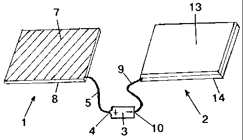
L'invention concerne un dispositif qui permet de soulager en toute sécurité la douleur chez les humains ou les animaux. Le dispositif comprend une paire de coussinets à placer à des points espacés sur le corps, p. ex. sur l'avant et l'arrière de l'abdomen pour traiter un mal de dos. Un des coussinets est muni d'une couche conductrice d'électricité, p.ex. du papier d'aluminium à placer sur le corps lorsqu'un traitement est requis, et l'autre coussinet comprend un noyau conducteur d'électricité disposé entre des couches isolantes. La couche et le noyau conducteurs d'électricité sont liés aux électrodes d'une pile sèche ou à une autre source de courant continu, ce qui amène le courant continu à circuler entre le corps et la couche conductrice d'électricité.


Abrégé anglais

A device for safely relieving pain in a human or animal includes a pair of pads for placing against a body at spaced apart locations, e.g. on the front and back of an abdomen for treating back pain. One of the pads has an electrically conductive layer, e.g. aluminum foil for placing against the body where treatment is required, and the other pad includes an electrically conductive core sandwiched between insulating layers. The electrically conductive layer and the core are connected to the electrodes of a dry cell or other source of direct current, whereby a direct current is caused to flow between the body and the electrically conducting layer.

Revendications

Note : Les revendications sont présentées dans la langue officielle dans laquelle elles ont été soumises.


1
Claims
1. A pain relief device that is light and portable that safely provides
electro-
therapeutic pain relief in a human or animal body comprising:
a thin flexible pad for placing against an area of a body spaced apart from
said
area of the body that is experiencing pain, said thin flexible pad including a
thin, flexible
electrically conductive core sandwiched between thin flexible electrically
insulating
layers, whereby the core is completely surrounded by said electrically
insulating layers;
a direct current electrical power source having positive and negative poles;
and
an electrical conductor connecting said core to said negative pole; and
means for electrically connecting said positive pole to an electrode, said
electrode,
thus connected, to be placed on the area of the body experiencing pain whereby
direct
current electricity will be caused to flow through said area of the body
experiencing pain
when said flexible pad is placed on an alternate area of the body.
2. The device of claim 1, wherein said core of said flexible pad is formed of
flexible,
electrically conductive metal from the group which include aluminum, copper,
silver,
gold, and platinum, and alloys or mixtures thereof.
3. The device of claim 1, wherein said core of said flexible pad is formed of
flexible
non-metal electrical conductors.
4. The device of claim 1, wherein said insulating layers of said flexible pad
are
formed of a thin flexible material selected from the group consisting of
plastic, latex, duct
tape, fabric, cloth, leather, rubber, nylon, and paper
5. The device of claim 1, wherein said power source has a constant direct
current

2
voltage produced using dry cell or other lightweight batteries.
6. The device of claim 1, wherein said conductive layer of said core of said
flexible
pad is formed of aluminum foil.
7. The device of claim 1, wherein said insulating layers of said flexible pad
are
formed of vinyl.
8. The device of claim 1, wherein said electrode and said flexible pad are
attached to
a belt in spaced apart relationship to each other, whereby, when the belt is
attached to the
body, the electrode and flexible pad are opposed to each other on opposite
sides of the
body.

Description

Note : Les descriptions sont présentées dans la langue officielle dans laquelle elles ont été soumises.


CA 02414398 2008-10-02
PAIN RELIEF DEVICE
This invention relates to a device for safely relieving pain and speeding
recovery, and in
particular, to a device safely utilizing direct current electricity for
relieving pain and speeding
recovery in a human or animal.
A need exists for a safe affective device or apparatus for relieving pain,
which also
accelerates recovery. There is a need for a safe device for relieving pain and
speeding recovery
that can be adapted to treat any part of the body There is a need for a safe
device for relieving
pain and speeding recovery that can be worn on the body allowing full
mobility, including
walking or sleeping, during use.
The object of the present invention is to meet the above-defined needs by
providing a
relatively simple device for relieving pain that speeds the recovery process
on a human or animal
body, which is both safe and effective.
Accordingly, the invention relates a device for relieving pain that speeds
healing in a
human or animal body comprising:
a first flexible conducting pad including a thin, flexible electrically
conductive layer for
placing against an area of a body experiencing pain;
a second flexible insulated pad for placing against another area of a body
spaced apart
from said one area, said second pad including a thin, flexible electrically
conductive core
sandwiched between flexible insulating layers, whereby the core is completely
surrounded by
said insulating layers;
a direct current electrical power source having positive (+) and negative (-
)electrodes; and
electrical conductors connecting said conductive layer of said first pad to
the positive (+)
electrode and said core to the negative (-) electrode, whereby direct current
is caused to flow

CA 02414398 2008-10-02
2
through the area of a body experiencing pain as a result of the electric field
created in the body by
the core. In references to positive (+) and negative (-) the convention
governing the name on the
pole as labeled on conventional A, AA, AAA, batteries is employed.
The invention is described below in greater detail with reference to the
accompanying
drawings, which illustrate a preferred embodiment of the invention, and
wherein:
Figure 1 is an isometric view of a device for relieving pain in accordance
with
the present invention;
Figure 2 is an isometric view of the device of Fig. I in a partially
delaminated
condition;
Figure 3 is an isometric view of the device of Fig. 1 showing the location of
a
core in an insulated pad;
Figure 3A is a cross section taken generally along line 3A-3A of Fig. 3;
Figure 3B is a cross section taken generally along line 3B-3B of Fig. 3;
Figure 4 is a front view of a belt incorporating a device in accordance with
the
present invention; and
Figures 5 to 7 are schematic side, back and front views, respectively of a
person wearing the belt of Fig. 4.
With reference to Figs. 1 and 2 of the drawings, the basic elements of a pain
relieving
device include first conducting pad and a second insulated pad indicated
generally at 1 and 2
respectively, and a low voltage DC source of power in the form of a dry cell
3, which provides a
constant direct current voltage. Suitable sources of power are provided by
batteries, including
ordinary A, AA and AAA dry cells. While the device illustrated in the drawings
is always "on"
and delivers a constant voltage when in use, the voltage can be varied.

CA 02414398 2008-10-02
3
The positive electrode 4 of the dry cell 3 is connected by an insulated wire
5, which is
copper or another electically conductive material, to a thin, flexible
electrically conductive layer
or sheet 7, which is bonded to a flexible backing 8 to form the conducting pad
1. As described
hereinafter in greater detail, the conducting pad 1 is adapted to be placed
against a part of a
human or animal body with the sheet 7 in contact with the body at the site of
the injury. The
sheet 7 is preferably formed of aluminum foil, which is a good electrical
conductor, but it can be
a foil or mesh formed of another flexible conductive material, e.g. copper,
silver, gold, and
platinum, an alloy, or any other substance, which will conduct electricity and
conform to a part of
a body, e.g. a shoulder or a knee. The backing 8 is intended to provide
support for the thin
conductive sheet 7, and, for such purpose, is formed of a flexible, non-
conductive material such
as vinyl. The conducting pad 1 should be constructed to be sufficient in area
to cover the entire
injury to be treated.
A second insulated wire 9 connects the negative electrode 10 of the dry cell 3
to a second
thin, conductive sheet (Fig. 2) defining a core 12 in the insulated pad 2. The
core 12, which is
also preferably formed of aluminum foil, but can also be formed of a foil or
mesh formed of
another flexible conductive material, such as but not limited to copper,
silver, gold, platinum or
any other conductive material or alloy thereof, is part of a laminate, i.e.
the core 12 is sandwiched
between thin flexible layers 13 and 14 of insulating material. The layers 13
and 14 can be
formed of any suitable flexible non-conductive material such as various
plastics, latex, duct tape,
fabric, cloth, leather or paper. It is merely necessary that the core 12 is
completely electrically
insulated. The insulated pad 2 should ideally be at least as large in surface
area as the conducting
pad 1. When the pads 1 and 2 are placed against a human or animal body at
spaced apart
locations to treat an area experiencing pain or injury, current will be caused
to flow between the

CA 02414398 2008-10-02
4
body and the sheet 7 of the conducting pad 1 which is placed over the area
experiencing pain.
The device allows current to flow exclusively between the body and the
conducting pad 1 as the
insulated pad 2 is a completely insulated core 12, preventing the flow of
current between the
body and the pad 2. In this respect, no current flows through the body as
would occur if the core
12 of the pad 2 were not insulated. The current flow at the site of the
conducting pad 1 in contact
with the body is caused as a result of interaction between the positively
charged sheet 7 and the
negatively charged body when the negatively charged core 12 of the insulated
pad 2 is also on the
body. Indeed, there will be a similar flow of current between any alternate
positively charged
electrode and the body when a negatively charged insulated core 12 is also on
the body. The
current flow will be restricted to the contact points made between the
alternate positively charged
electrode and the skin.
Referring to Fig. 4 the device of the present invention can be incorporated in
belt 15 to be
placed around the waist of a person 16 (Figs. 5 to 7) for treatment of lower
back pain. The belt
15 includes a first pad 1 with the conductive sheet 7, a second pad 2
containing a conductive core
12 and a DC power source 3, in this case a 3-volt battery pack attached to the
belt 15. The
battery pack 3 is attached to the pad 1 and 2 in the manner described above.
The belt 15 keeps the
pad 1 and 2 firmly in position during treatment, and can be worn for long
periods of time even
when the person is moving. The pad 1 is large enough to cover an injured area,
and the core 12 in
the pad 2 should be at least as large as the conductive sheet 7 of the pad 1.
When using the invention shown in Figs. 5 to 7 for back therapy, the pad 1 is
held against
the back of a person 16 with the conductive sheet 7 in maximum contact with
the skin of the
person and the insulated pad 2 is held against the person's abdomen. While it
is preferred, it is
neither necessary that the pads 1 and 2 be the same size nor that they be
exactly opposite each

CA 02414398 2008-10-02
other on the person. The 3-volt battery pack 1 is connected to the pads 1 and
2 in the manner
described above.
Other embodiments of the invention utilize a conducting pad 1 and an insulated
pad 2 of
appropriate size, depending on the application, for placing on any area of the
body experiencing
pain. If tape or some form of harness is used the device can be worn allowing
full mobility.
In yet another embodiment of the invention, the insulated pad 2 can be placed
on the body
as described above and a point electrode be used in place of a conducting pad
1 to relieve pain in
a very localized area. This will concentrate the current flow to the location
experiencing pain
safely.
Another embodiment of this invention can use an insulated pad 2 with an
alternate
electrode in place of a conducting pad 1.
Another embodiment of the invention utilizes an insulated pad 2 used as above
and the
appropriate electrode to treat any ailment of the body of humans and animals
that can be treated
using electrical methods of therapy.
Another embodiment of the invention uses a single insulated pad 2 and several
conducting pads 1 or alternate electrodes wired to the same power source in
order to treat more
than one injury on the body simultaneously.

Dessin représentatif
Une figure unique qui représente un dessin illustrant l'invention.
États administratifs

2024-08-01 : Dans le cadre de la transition vers les Brevets de nouvelle génération (BNG), la base de données sur les brevets canadiens (BDBC) contient désormais un Historique d'événement plus détaillé, qui reproduit le Journal des événements de notre nouvelle solution interne.

Veuillez noter que les événements débutant par « Inactive : » se réfèrent à des événements qui ne sont plus utilisés dans notre nouvelle solution interne.

Pour une meilleure compréhension de l'état de la demande ou brevet qui figure sur cette page, la rubrique Mise en garde , et les descriptions de Brevet , Historique d'événement , Taxes périodiques et Historique des paiements devraient être consultées.

Historique d'événement

Description Date
Le délai pour l'annulation est expiré 2022-06-23
Lettre envoyée 2021-12-23
Lettre envoyée 2021-06-23
Lettre envoyée 2020-12-23
Requête visant le maintien en état reçue 2019-11-22
Représentant commun nommé 2019-10-30
Requête visant le maintien en état reçue 2018-10-25
Requête visant le maintien en état reçue 2017-12-11
Requête visant le maintien en état reçue 2016-10-19
Requête visant le maintien en état reçue 2015-11-06
Requête visant le maintien en état reçue 2014-11-18
Requête visant le maintien en état reçue 2013-12-23
Requête visant le maintien en état reçue 2012-12-11
Accordé par délivrance 2010-02-23
Inactive : Page couverture publiée 2010-02-22
Demande de publication de la disponibilité d'une licence 2009-12-04
Préoctroi 2009-12-04
Inactive : Taxe finale reçue 2009-12-04
Un avis d'acceptation est envoyé 2009-09-22
Lettre envoyée 2009-09-22
Un avis d'acceptation est envoyé 2009-09-22
Inactive : Approuvée aux fins d'acceptation (AFA) 2009-02-04
Modification reçue - modification volontaire 2008-10-02
Inactive : Dem. de l'examinateur par.30(2) Règles 2008-04-02
Modification reçue - modification volontaire 2007-05-07
Inactive : Dem. de l'examinateur par.30(2) Règles 2006-11-28
Modification reçue - modification volontaire 2006-03-17
Inactive : CIB de MCD 2006-03-12
Inactive : Lettre officielle 2006-03-03
Modification reçue - modification volontaire 2006-02-13
Modification reçue - modification volontaire 2006-01-26
Modification reçue - modification volontaire 2005-12-07
Inactive : Dem. de l'examinateur par.30(2) Règles 2005-08-17
Demande publiée (accessible au public) 2004-06-23
Inactive : Page couverture publiée 2004-06-22
Modification reçue - modification volontaire 2004-05-27
Modification reçue - modification volontaire 2004-05-26
Modification reçue - modification volontaire 2004-05-25
Inactive : Dem. de l'examinateur art.29 Règles 2003-11-28
Inactive : Dem. de l'examinateur par.30(2) Règles 2003-11-28
Lettre envoyée 2003-03-31
Requête d'examen reçue 2003-02-25
Exigences pour une requête d'examen - jugée conforme 2003-02-25
Déclaration du statut de petite entité jugée conforme 2003-02-25
Toutes les exigences pour l'examen - jugée conforme 2003-02-25
Inactive : Correspondance - Formalités 2003-02-25
Inactive : CIB en 1re position 2003-02-25
Inactive : Certificat de dépôt - Sans RE (Anglais) 2003-02-07
Demande reçue - nationale ordinaire 2003-02-03

Historique d'abandonnement

Il n'y a pas d'historique d'abandonnement

Taxes périodiques

Le dernier paiement a été reçu le 2009-12-04

Avis : Si le paiement en totalité n'a pas été reçu au plus tard à la date indiquée, une taxe supplémentaire peut être imposée, soit une des taxes suivantes :

  • taxe de rétablissement ;
  • taxe pour paiement en souffrance ; ou
  • taxe additionnelle pour le renversement d'une péremption réputée.

Les taxes sur les brevets sont ajustées au 1er janvier de chaque année. Les montants ci-dessus sont les montants actuels s'ils sont reçus au plus tard le 31 décembre de l'année en cours.
Veuillez vous référer à la page web des taxes sur les brevets de l'OPIC pour voir tous les montants actuels des taxes.

Historique des taxes

Type de taxes Anniversaire Échéance Date payée
Taxe pour le dépôt - petite 2002-12-23
Requête d'examen - petite 2003-02-25
TM (demande, 2e anniv.) - petite 02 2004-12-23 2004-11-08
TM (demande, 3e anniv.) - petite 03 2005-12-23 2005-10-11
TM (demande, 4e anniv.) - petite 04 2006-12-25 2006-11-07
TM (demande, 5e anniv.) - petite 05 2007-12-24 2007-10-15
TM (demande, 6e anniv.) - petite 06 2008-12-23 2008-11-06
TM (demande, 7e anniv.) - petite 07 2009-12-23 2009-12-04
Taxe finale - petite 2009-12-04
TM (brevet, 8e anniv.) - petite 2010-12-23 2010-10-14
TM (brevet, 9e anniv.) - petite 2011-12-23 2011-12-13
TM (brevet, 10e anniv.) - petite 2012-12-24 2012-12-11
TM (brevet, 11e anniv.) - petite 2013-12-23 2013-12-23
TM (brevet, 12e anniv.) - petite 2014-12-23 2014-11-18
TM (brevet, 13e anniv.) - petite 2015-12-23 2015-11-06
TM (brevet, 14e anniv.) - petite 2016-12-23 2016-10-19
TM (brevet, 15e anniv.) - petite 2017-12-27 2017-12-11
TM (brevet, 16e anniv.) - petite 2018-12-24 2018-10-25
TM (brevet, 17e anniv.) - petite 2019-12-23 2019-11-22
Titulaires au dossier

Les titulaires actuels et antérieures au dossier sont affichés en ordre alphabétique.

Titulaires actuels au dossier
FREDERICK WILLIAM POLLOCK
Titulaires antérieures au dossier
S.O.
Les propriétaires antérieurs qui ne figurent pas dans la liste des « Propriétaires au dossier » apparaîtront dans d'autres documents au dossier.
Documents

Pour visionner les fichiers sélectionnés, entrer le code reCAPTCHA :


Pour visualiser une image, cliquer sur un lien dans la colonne description du document. Pour télécharger l'image (les images), cliquer l'une ou plusieurs cases à cocher dans la première colonne et ensuite cliquer sur le bouton "Télécharger sélection en format PDF (archive Zip)" ou le bouton "Télécharger sélection (en un fichier PDF fusionné)".

Liste des documents de brevet publiés et non publiés sur la BDBC .

Si vous avez des difficultés à accéder au contenu, veuillez communiquer avec le Centre de services à la clientèle au 1-866-997-1936, ou envoyer un courriel au Centre de service à la clientèle de l'OPIC.


Description du
Document 
Date
(aaaa-mm-jj) 
Nombre de pages   Taille de l'image (Ko) 
Abrégé 2002-12-22 1 19
Description 2002-12-22 6 341
Dessins 2002-12-22 3 103
Revendications 2002-12-22 2 124
Dessin représentatif 2004-05-27 1 16
Description 2004-05-24 5 211
Revendications 2004-05-24 2 56
Abrégé 2004-05-24 1 17
Dessins 2004-05-24 3 46
Abrégé 2004-05-25 1 14
Revendications 2004-05-25 2 48
Description 2004-05-26 5 230
Revendications 2004-05-26 2 62
Abrégé 2004-05-26 1 20
Dessins 2004-05-26 3 59
Description 2006-03-16 5 228
Revendications 2006-03-16 2 60
Revendications 2007-05-06 2 53
Description 2008-10-01 5 234
Revendications 2008-10-01 2 70
Dessin représentatif 2010-01-26 1 9
Certificat de dépôt (anglais) 2003-02-06 1 159
Accusé de réception de la requête d'examen 2003-03-30 1 185
Avis de rappel: Taxes de maintien 2004-09-26 1 123
Avis de rappel: Taxes de maintien 2005-09-25 1 119
Avis de rappel: Taxes de maintien 2006-09-25 1 118
Avis de rappel: Taxes de maintien 2007-09-24 1 130
Avis de rappel: Taxes de maintien 2008-09-23 1 120
Avis de rappel: Taxes de maintien 2009-09-23 1 120
Avis du commissaire - Demande jugée acceptable 2009-09-21 1 162
Avis de rappel: Taxes de maintien 2010-09-26 1 121
Avis de rappel: Taxes de maintien 2011-09-25 1 120
Avis de rappel: Taxes de maintien 2012-09-24 1 121
Avis de rappel: Taxes de maintien 2013-09-23 1 120
Avis de rappel: Taxes de maintien 2014-09-23 1 119
Avis de rappel: Taxes de maintien 2015-09-23 1 118
Avis de rappel: Taxes de maintien 2016-09-25 1 126
Avis de rappel: Taxes de maintien 2017-09-25 1 120
Avis de rappel: Taxes de maintien 2018-09-24 1 119
Avis de rappel: Taxes de maintien 2019-09-23 1 120
Avis du commissaire - Non-paiement de la taxe pour le maintien en état des droits conférés par un brevet 2021-02-09 1 545
Courtoisie - Brevet réputé périmé 2021-07-13 1 549
Avis du commissaire - Non-paiement de la taxe pour le maintien en état des droits conférés par un brevet 2022-02-02 1 542
Paiement de taxe périodique 2018-10-24 1 49
Correspondance 2003-02-06 1 17
Correspondance 2003-02-24 2 67
Taxes 2004-11-07 2 110
Taxes 2005-10-10 3 203
Taxes 2006-11-06 2 105
Taxes 2007-10-14 2 137
Taxes 2008-11-05 1 80
Correspondance 2009-12-03 2 85
Taxes 2009-12-03 2 98
Taxes 2010-10-13 1 213
Taxes 2011-12-12 1 69
Taxes 2012-12-10 1 69
Taxes 2013-12-22 1 135
Taxes 2014-11-17 1 69
Paiement de taxe périodique 2015-11-05 1 68
Paiement de taxe périodique 2016-10-18 1 142
Paiement de taxe périodique 2017-12-10 1 142
Paiement de taxe périodique 2019-11-21 1 55