Note : Les descriptions sont présentées dans la langue officielle dans laquelle elles ont été soumises.
CA 02414494 2002-12-24
Filter module
Description
The invention refers to a filter module with filter layers from a filter
medium, in
particular with filter layers from filter strata that alternate with layers
from draining
spacer elements and the draining spacer elements have alternately flow
elements
on the one hand and seating elements on the other to the filtrate and
unfiltrated
material chamber, while means are provided for their reciprocal joining.
Various constructions of such filter modules are known, whereby it is common
to
the majority of these filter modules that the filter layers are made of flat
materials
like, for example, filter cartons, papers, mats or fabrics.
As a rule filter strata are made of deep filtering material having organic
andlor
inorganic fibrous and/or granular materials. As a rule, as base material for
filter
strata cellulose or synthetic fibres are used, into which diatomaceous earth,
perlites or metal oxides or other filtration-active substance can be embedded.
In
this connection diatomaceous earth and perlites serve the purpose of
increasing
the internal surface and consequently the capacity to absorb sediment.
The field of application of the filter strata extends from purification and
treatment
of liquids in the entire beverage industry up to the pharmaceutical and
chemical
industries. The filter strata have not only a sieving effect by which coarse
particles
are retained on the surface of the filter strata, but especially a depth
action for
fine particles that are retained in the hollow spaces within the deep-bed
fitter
material. Depending on the type of material used, these filter strata may have
also an adsorption effect and for various fields of application the surface
can be
subjected to post-treatment so that in the dry and moist state no fibrous
particles
could be loosened.
From the US 4,347,208 a filter module made from filter cells is known, the
core of
which is made from a plastic draining spacer, against which on both sides a
filter
layer from filter medium in the form of flat discs abuts. In the centre of the
filter
CA 02414494 2002-12-24
2
cell a filtrate opening is provided. For the purpose of sealing such filter
cells have
to be co-moulded on the outer edge with a plastic material, what is elaborate
and
costly, because for this purpose special moulds have to be used that have to
be
adapted to suit the geometry of the filter cell. The sealing of the filter
cells against
the unfiltrated material chamber is carried out by pressing together both
filter
material layers which contact only in the edge region and by forming a U-
shaped
plastic element overlapping the edge region.
EP 0 233 999 also describes such a filter module, wherein between the filter
cells
additional so called outer spacers are provided which keep the filter cells at
a
distance from one another so that to prevent the damaging, collapsing or
swelling
of the filter cells. In addition, the radial flow between the filter cells is
to be
improved. The inner and outer spacers have different designs, so that
different
tools are required for the manufacture. Co-moulded filter cells are used for
this
filter module also.
A filter module of filter cells stacked on top of one another becomes apparent
from EP 0 291 883 A3. To manufacture the module described filter pockets with
inside situated drainage material are produced that are enveloped in a leak-
proof
manner by a sealing element and a plastic material compound. Afterwards the
pockets are so stacked on top of one another that the fluid can penetrate
between the cells. Additional components are required for this filter module
also
to ensure the spaced arrangement of the filter discs. The flow through the
filter
module takes place in the plane of the filter strata which then have to be
flown
through perpendicularly to the plane of the layer to affect the filtration.
These filter
cells cannot be backwashed without special steps.
A further filter module is known from DE 37 41 552 A1. The filter module, in
which
a plurality of filter cells is combined, is constructed with a central carrier
tube on
which the filter cells are axially compressed between finro adapter elements
firmly
mounted on both ends of the carrier tube and held sealed against one another.
The interior of the carrier tube is connected with the interior of each filter
cell via
ports provided in the circumferential wall of the carrier tube and thus forms
a
common discharge channel for the filtrate of all filter cells.
CA 02414494 2002-12-24
3
Due to the lack of backwashing capability of some modules lately moves have
been made to use gap-free arrangements of filter layers.
From 198 36 949.2-27 a filter module with collector/distributor strata for the
filtrate
and unfiltrated material is known, between each of which at least one filter
stratum made from deep filtering material is provided. Both the filter strata
and
the collector/distributor strata are made from the same base material and have
different intensities of separation. The collector/distributor strata are
sealed
alternately to the filtratelunfiltrated material chamber. The sealing elements
can
be made from formed parts that have means for reciprocal joining.
From DE 198 37 257 A1 a filter module is known, that has layers of a filter
medium, between which draining spacer elements are arranged. The draining
spacer elements are also alternately sealed to the filtrate/unfiltrated
material
chamber. Furthermore, the draining layers have also flow elements that
comprises a solid frame with a bore or grooves situated in the plane of the
draining layers. The sealing elements and/or the flow elements have means for
reciprocal joining, though either the flow elements or the sealing elements
can be
joined with one another.
The draining spacer elements are constructed integrally with a sealing element
and the flow element, by virtue of which cost-effective components can be
manufactured which only need to be combined with the filter strata and joined
together. Since the flow elements and sealing elements have the same thickness
as the draining spacer elements, during the assembly of the filter module the
filter
strata are not compressed in the region of the edge, so that by-passes in this
region cannot be avoided. The filter strata are open to the flow in the
lateral edge
regions.
The purpose of the joining means is only to fix the entire module without
improving the sealing.
<'
CA 02414494 2002-12-24
4
The object of the invention is a filter module that combines the advantages of
this
known filter module with an improved sealing in the region of the edge, which
can
be backwashed also and can be operated in any direction of flow.
This objective is achieved by a filter module that is characterised in that
the
draining spacer elements are constructed to seal by pressing the filter layers
and
that at least some of the draining spacer elements have connecting means in
the
region of at least a filtrate/unfiltrated material chamber, while the
connecting
means of these spacer elements interact with the connecting means of at least
one further spacer element.
Under filtrate or unfiltrated material chambers the space surrounding the
filter
module and the collecting channels for filtrate or unfiltrated material
extending in
the axial direction of the filter module are understood. The filter module has
usually a centrally an-anged filtrate/unfiltrated material chamber, however, a
plurality of such filtrate/unfiltrated material chambers extending through the
filter
module is also possible.
This filter module has a number of advantages.
By virtue of the flat resting of the filter layers on the draining spacer
elements,
whereby the filter layers are clamped together in the region of the edge
between
the spacer elements and due to the reciprocal connection of the draining
spacer
elements by connecting means an altogether stable filter module is produced
that
cannot warp and can be backwashed. A deformation of the filter layers during
the
backwash is effectively prevented.
Due to that fact that the draining spacer elements are provided on both sides
of
the filter layers and consequently the filter layers are supported on both
sides,
filter materials with lower inherent rigidity may be also used for the
filtration.
Due to the rigid connection, particularly on the outer edge, an inherently
stable
filter module is produced, that withstands all loads during storage, delivery
and
operation. Furthermore, a damaging of the filter layers during assembly and
CA 02414494 2002-12-24
dismantling from the filter housing is avoided. When annular filter layers are
used,
the filtratelunfiltrated material channel is, as a rule, provided centrally,
where the
draining spacer elements can also have connecting elements, thus additionally
increasing the stability.
5
By virtue of the steps taken according to the invention the resistance of the
filter
module to recoil impacts is also clearly improved, what is significant when
impacts of vacuum or pressure surges occur due to switching errors.
Since the connection of the spacer elements is carried out to one another, the
overall height of the filter module can be arbitrarily chosen. Furthermore,
the
diameters of the filter layers and of the draining spacer elements can be
chosen
to suit the diameter of conventional filter housings, so that the use of known
filter
housings is possible without any problem and without the loss of effective
filtering
surface.
Whereas in the case of conventional filter cells an adhesion of the filter
layers in
the body region of the filter cells cannot be prevented, this problem does not
occur due to the draining spacer elements present on both sides of the filter
layers. The fitter layers are used to their optimum and particularly in the
case of
low differential pressure.
Moreover, the filtration is possible in both directions, i.e. the module can
be
operated also in the reverse direction. Thus an absolute residual filtration
can be
carried out, i.e. after the filtration no unfiltrated material will remain in
the housing.
This is of significance especially in the case when expensive solutions are
filtrated. A cleaning of the filter housing after the filtration of, for
example, toxic
fluids, can be omitted, so that contact with the toxic materials can be
avoided.
The uppermost and lowermost filter layer of the filter module can be, for
example,
closed off with non-draining spacer elements. It is also possible to use
conventional filter cells with connecting means on the co-moulded outer edge,
as
top and bottom closures.
CA 02414494 2002-12-24
6
Preferably the connecting means of adjacent spacer elements interact. It is,
however, possible that the connecting means overlap one or several adjacent
spacer elements and interact only with the connecting means of one or several
of
the successive spacer elements.
The spacer element preferably comprises a draining element, at least one
sealing
element and/or one flow element. The number of the sealing or flow elements
depends on the number of the filtrate/unfiltrated material chambers bordering
the
respective spacer element.
In an advantageous manner two different draining elements (first and second
draining elements) are provided that are alternately arranged in the filter
module.
Preferably the first spacer element has the sealing element on the inner
circumference and the second spacer element the sealing element on the outer
circumference.
The sealing elements and the flow elements of the first draining spacer
element
are preferably thicker than the sealing and flow elements of the second
draining
spacer elements. By virtue of this, depending from the thickness of the filter
layer,
after the assembly of the filter module between the first draining spacer
element
and the filter layer in the region that is not clamped together a gap with a
smaller
or greater width is formed.
The first spacer element between the draining element and the sealing element
and the flow element has preferably an inner wedge-shaped connecting element
and/or an outer wedge-shaped connecting element.
The wedge-shaped connecting elements) has (have) at least one upper and at
least one lower wedge surface with angles of inclination between 10°
and 60°.
The wedge-shaped connecting elements have preferably the same thickness, as
the sealing element and the flow element and they taper radially outward up to
the thickness of the draining element. Due to this a continuous transition
between
the sealing element and the flow element, respectively, and the draining
element
CA 02414494 2002-12-24
7
is produced, what is advantageous as far as the sealing is concerned. During
the
assembly the filter stratum is continuously compressed by the second spacer
elements towards the region of the edge of the spacer element, so that the
filter
stratum is not subjected to any uncontrolled deformation which could lead to
by-
passes.
The wedge-shaped connecting elements have preferably two wedge surfaces
each, whereby the wedge surface has an angle of inclination a~=40°-
60°,
preferably 45°, in the region of x<1 mm and the second wedge surface in
the
adjoining region has an angle of a2<20°.
The draining element is preferably constructed integral with the sealing
element
and/or the flow element and/or the wedge-shaped connecting element, so that
for
example a single-piece injection moulded plastic part can be manufactured.
A further simplification is achieved by that the connecting means are also
integrally constructed with the spacer element.
The connecting means engage one another only when the spacer elements and
the filter layers are compressed after the assembly to form a filter module.
On this
occasion the filter layers are compressed in a sealing manner by the draining
spacer elements. After the removal of the assembly pressure and after the
interaction of the connecting means they have to withstand corresponding
tensile
forces. The connecting means are therefore preferably so dimensioned that they
would withstand a tensile stress that corresponds to a clamping pressure to
seal
by pressing the filter layers between 1 N/mm2 and 100 N/mm2, preferably
2 N/mm2 to 30 N/mm2.
The connecting means can be executed in various manners. The connecting
means of the spacer elements preferably interact in a form-locking manner.
Another embodiment provides that the connecting means of the spacer element
interact in a force-locking manner.
CA 02414494 2002-12-24
8
Since the spacer elements have on their edge regions flow elements and sealing
elements, the connecting means are provided preferably on the flow elements
and sealing elements, in particular moulded on them when one deals with a one-
piece embodiment.
In an advantageous manner the connecting elements comprise stimaps that
engage the snap-in tugs. The stirrups may be U- or L-shaped.
The stirrups are arranged both facing upward or downward. An alternating
arrangement of upward and downward facing stirrups is preferred.
To enable the production of an as rigid as possible module unit, the stirrups
are
provided preferably directly adjacent to one another in the circumferential
direction of the spacer elements.
According to a further preferred embodiment the stim~ps can also be arranged
at
a distance from one another in the circumferential direction of the spacer
element, while the maximum distance is 500 mm. The connecting elements are
evenly distributed over the circumference, while their number depends on the
dimension of the circumference. The connecting means, particularly the
stimaps,
serve as protection against influences on the clamped edge of the filter layer
in
the radial direction.
A further embodiment provides that the connecting means are a continuous
groove formed on a spacer element and snap-in hooks arranged on another
spacer element, which engage the groove. The continuous groove may be
provided in the sealing element of the spacer element or in the flow element.
The
groove is preferably bordered by snap-in rings.
The snap-in lugs, snap-in hooks, snap-in rings andlor stirrups have preferably
sliding slopes on their external sides. By virtue of this the joining together
and the
snapping in of the connecting means is facilitated. During the assembly of the
filter module the filter layers and the draining spacer elements are stacked
on top
of one another and subsequently the entire packet is compressed, whereby the
CA 02414494 2002-12-24
9
stirrups, snap-in lugs, etc. engage one another. On this occasion the
connecting
means have to pass through the respective outer surfaces of the connecting
partner while the sliding slopes facilitate this operation.
To ensure a secure holding together, the contact surfaces of the form-locked
connecting means are preferably provided inGined, while in an advantageous
manner the respective engaging surface is inward inclined in the direction
opposing the connecting means to be engaged. A clip-like connection is
achieved
by this.
Further embodiments of the connecting means may be sleeves and dowels with
or without teeth engaging them, T-shaped snap-in elements engaging one
another on both sides or arrow-shaped snap-in elements engaging one another
on both sides.
According to a further embodiment continuous fastening means like, for
example,
hook rings, may be provided on the spacer elements, while a net or scxeen
enveloping the filter is fastened on the fastening means. In the case of this
embodiment the net or screen serves also as a connecting means that holds the
spacer elements and consequently the filter module together.
The connecting means may be provided exclusively on the outer circumference
of the spacer elements. It is, however, possible that the connecting means are
provided in addition to the outer circumference of the spacer elements also on
the
inner circumference of the spacer elements, whereby the inner circumference
means the edge region that bounds the collecting and consequently
filtrate/unfiltrated material chambers provided in the interior of the filter
module.
The sealing and/or flow elements are constructed preferably as bead-like
thickenings of the draining spacer elements.
Exemplary embodiments of the invention are explained in detail in the
following
based on the drawings. They show in:
CA 02414494 2002-12-24
Fig.1 - a perspective illustration of the filter module,
Fig.2a - a partial section through the filter module shown in Fig.1 along the
line
A A,
5
Fig.2b - a partial section through a draining spacer element,
Fig.3a - an enlarged perspective illustration of the stirrup,
10 Figs.3b,c - top views on a section of the circumferential edge of a spacer
element
according to two embodiments,
Fig.4 - a partial section through a filter module according to a further
embodiment,
Fig.S - a partial top view on the filter module shown in Fig.4,
Figs.6a,b - top views on sectors of the draining spacer elements, and
Fig.1 - a partial section through a filter module according to a further
embodiment.
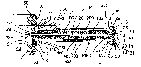
Fig.1 is a perspective illustration of a complete filter module 1. Filter
layers in the
form of filter strata 4 alternate with the first and second draining spacer
elements
10, 20. All components of the filter module 1 are mounted above one another on
a central tube 2 that has a lower end piece 8 (see Fig.2) and an upper end
piece
3 that secures the filter strata 4 and the draining spacer elements 10, 20 on
the
central tube 2.
The second draining spacer elements 20 have on their external side upward and
downward facing U-shaped stirrups 23, that engage the snap-in lugs 13, 14 of
the
first draining spacer elements 10. The stirrups 23 and the snap-in tugs 13, 14
form together a clip-like connection. In the embodiment shown in Fig.1 the
stirrups are arranged on the outer circumference without any gaps, producing a
CA 02414494 2002-12-24
11
stable filter module 1 that is easy to handle as a whole and will not be
distorted in
use.
In Fig.2a shows a section along the line A-A through the filter module shown
in
Fig.1. For the sake of simplicity only two filter strata 4a and 4b are shown
with the
associated draining spacer elements 10a,b and 20.
The first draining spacer elements 1 Oa,b have annular sealing elements 11 a,
11 b
that have a hexagonal cross-section in the embodiment shown here. Distributed
over the outer circumference of the annular sealing elements 11 a, 11 b,
radially
outward inner wedge-shaped connecting elements 103 are joined, the connecting
elements having an upper and a lower wedge-shaped surtace 104, 105. These
wedge-shaped connecting elements 103 taper radially outward, whereby the
thickness is reduced from the thickness of the sealing element to the
thickness of
the draining element 100 and the thickness of the corresponding webs 118, 118'
of the draining element 100 (see also Fig.6a). Radially outward outer wedge-
shaped connecting elements 107 join the draining element 100 with upper and
lower wedge surfaces 108, 109. The wedge-shaped connecting elements 107
blend into the flow elements 12a, 12b that form a ring, the thickness of which
corresponds to the thickness of the sealing element 11 a, 11 b. On the flow
elements 12a,b snap-in lugs 13 are~formed and flow channels 18 are provided
centrally in the flow elements 12a,b. The draining spacer elements, the wedge-
shaped connecting elements, the sealing elements and the flow elements are
constructed integral, for example as a formed part made from plastic material.
Between the draining elements 100 and the respective adjacent filter strata
4a,
4b a gap-shaped intermediate space 130 is provided, so that the filter strata
4a,b
in this region is not subjected to any load and can expand unhindered by
swelling. By virtue of this the complete functional capacity and effectiveness
of
the filter layer 4a,b is assured. The width of the gap is determined by the
thickness of the filter stratum 4a,b. Without the necessity to modify the
draining
spacer elements 10a,b, 20, filter layers with different thicknesses can be
built in.
When the filter module is operated with a reverse direction of flow, the gap
130
may close depending on the thickness of the filter stratum 4a,b and a gap may
be
CA 02414494 2002-12-24
12
formed between the draining element 200 and the adjacent filter stratum or
filter
layer.
During the assembly operation the wedge-shaped connecting elements with the
second draining spacer elements 20 exert in the radial direction a continuous
pressure on the filter stratum, resulting in an improved sealing. The second
draining spacer elements 20 have an annular flow element 22 with flow channels
33. The thickness of the annular flow element 22 is greater than that of the
radially outward joining draining element 200, that is joined radially outside
by the
annular sealing element 21. The second draining spacer element 20 is
preferably
also manufactured from synthetic material in one piece. On the outside of the
sealing element 21, that is constructed as a sealing ring having a thickness
corresponding to the thickness of the draining spacer element 20, stirrups 23
are
moulded. The stirrups 23 extend both upwards and downwards and have on their
inside stirrup lugs 26 and contact surfaces 27 and on their outside sliding
slopes
30.
The filter strata 4a,b and the spacer elements 10a,b, 20 are mounted above one
another on the central tube 2, on which the lower end piece 8 and the upper
end
piece 3 are fastened. These end pieces 3 and 8 have on their faces annular
sealing elements 50 that are constructed as flat seals. The interior of the
central
tube 2 forms the filtrate/unfiltrated material channel 40.
Between the end pieces 3 and 8 fitted with plugs 7 the following components
are
clamped in, starting from the top: intermediate element 9 from filter
material,
sealing element 11 a, filter stratum 4, flow element 22, filter stratum 4b,
sealing
element 11 b and intermediate element 9. Due to the wedge-shaped connecting
elements 103 the sealing elements 11 a and 11 b are constructed on both sides
as
bead-like thickenings of the draining elements 100 and have in the embodiment
shown here a hexagonal cross-section. The bead-like sealing elements 11 a and
11 b abut in a sealing manner against the intermediate element 9 on the one
hand
and the inner edge 5 of the filter strata 4a and 4b on the other.
CA 02414494 2002-12-24
13
The flow element 22, that by means of flow channels 33 represents a connection
between the space between the strata layers 4a and 4b and the
filtratelunfiltrated
material chamber 40, is also constructed on both sides as a bead-like
thickening
of the second draining spacer element 20.
When attaching the components to the filter module 1, by virtue of this
construction of the sealing elements 11 a and 11 b and of the flow element 22,
the
filter strata 4a and 4b are compressed and sealed on the inner edge 5, so that
any bypass in this region will be prevented.
On the outer circumference the second draining spacer element 20 has a sealing
element 21 for the purpose of forming a seal against the surrounding space
that
forms the filtrate/unfiltrated material chamber 41.
The flow elements 12a,b represent the connection between the space above and
below the filter strata 4a, 4b and the filtrate or unfiltrated material
chamber 41.
Above and below the flow channels 18 snap-in lugs 13, 14 with sliding slopes
31
are provided that in the assembled state interact with the stin-up lugs 26 and
form
a clip-like connection.
Between the sealing element 21 and the flow elements 22 the outer edge 6 of
the
filter strata 4a and 4b is compressed.
The arrows show the direction of flow of the unfiltrated material and the
filtrate.
The unfiltrated material is conveyed from the unfiltrated material chamber 41
and
reaches the filter strata 4a and 4b through the flow channels 18. After
passing
through the filter strata 4a and 4b the filtrate is collected in the region of
the
second draining spacer element 20 and flows through its flow element 22 into
the
filtrate chamber 40 in the interior of the central tube 7. The direction of
the flow
may also be reversed. In that case the space 40 forms the unfiltrated material
chamber and space 41 the filtrate chamber.
Fig.2b shows a further embodiment of the wedge-shaped connecting element
103. Instead of a single wedge surface two wedge-shaped surfaces 104a,b and
CA 02414494 2002-12-24
14
106a,b each are provided on the upper and lower sides. The wedge surfaces
104a, 106a have a greater incline than the wedge surfaces 104b, 106b which
border the draining element 100. This means that for the angles concerned
a~>a2. The wedge-shaped connecting element 107 (see Fig.2a) can be
correspondingly constructed.
Fig.3a shows the perspective illustration of four stirrups 23. These stirrups
are
formed on the annular sealing element 11 as U-shaped stirrups facing upward
and downward. Each stirrup 23 has two vertical legs 24 and a connecting
transversal leg 25, on the rear side of which a stirrup lug 26 each is
provided.
Fig.3b shows the top view on a section of the circumferential edge of a
draining
spacer element 10a. The flow channels 18 are provided centrally and the snap-
in
lugs 13 and 14 are provided above and below the flow channels 18 distributed
evenly at a distance from one another over the circumferential edge. The snap-
in
lugs 13 and 14 have sliding surfaces 31 on their external sides.
Fig.3c illustrates a further embodiment, wherein instead of snap-in lugs 13
and 14
snap-in rings 102a, 102b are provided which bound a groove 101 situated in
between, in which groove the flow channels 18 are provided. It is also
possible to
arrange the embodiments illustrated in Figs.3b and 3c on the sealing elements
instead of on the flow elements.
Fig.4 illustrates a further embodiment, wherein both the sealing elements 21
and
the flow elements 12 have annular pressure shoulders 19 and 32, respectively.
The stirrups 23a,b are provided on the sealing element 21 facing alternating
upward and downward, as this becomes obvious from Fig.S. Accordingly, the
snap-in lugs 14', 14" as well as 13', 13" are also provided alternately. The
contact
surface 15 of the snap-in lugs 14' and the contact surface 27 of the
transversal
leg 25 of stirrup 23a are provided with an incline, while the contact surface
15 is
inGined inwards (see Fig.4). Consequently a secure holding is assured, so that
the stirrups 23a cannot buckle outward under load. Thus a clip-like locking or
a
clip-like connection is produced.
CA 02414494 2002-12-24
Fig.6a illustrates a sector of a circular first spacer element 10. On the
inner
circumference there is the annular sealing element 11 a, to which radiaNy
outward
the wedge-shaped connecting elements 103 with the upper wedge surfaces 104
are joined, which blend into the radial webs 118 of the draining element 100.
5 Furthermore, shortened radial webs 118' are provided, that extend inward
from
the annular flow element 12a provided on the outer circumference of the
draining
spacer element 10. The radial webs 118, 118' are joined with one another by
circular webs 119. The criss-crossed sections of the circular webs 118, 118'
as
well as the areas 128, which are shown only in the form of an example on one
10 web 118', have a thickness that is reduced when compared with the other
webs
or web sections so that to enable a transverse flow if required.
The webs 118, 118' have wedge-shaped connecting elements 107 on the radially
external end, the upper wedge surface 108 of these connecting elements being
15 visible. The annular flow element 12a with the flow channels 18 and the
snap-in
lug 13 joins this.
Fig.6b illustrates a sector of a circular second spacer element 20. The
stirrups 23
are formed on the outer circumference of the annular sealing element 21. On
the
internal circumference there is the flow element 22 with the flow channels 33.
Between the flow element 22 and the sealing element 21 radial webs 28, 28' and
circular webs 29 are provided, while there are continuous webs 28 and
shortened
webs 28'. The spacing of the radial webs 28, 28' is made to suit the filter
material,
so that to ensure an optimum support of the filter layer both during the
filtration
and during the backwashing. Thus the width, length and arrangement of the webs
28,28' and 29 are to be made to suit the respective filter material and the
filtration
task. The criss-crossed sections of the circular webs 29 as well as the areas
228,
which are shown only in the form of an example on one web 28; have a thickness
that is reduced when compared with the other webs or web sections so that to
enable a transverse flow.
Fig.7 illustrates a further embodiment that shows the connection in the region
of
the filtrate/unfiltrated material channel 40. In this embodiment a central
tube 2 is
omitted, because the first draining spacer elements 10 with the annular
sealing
CA 02414494 2002-12-24
16
element 11 have stirrups l6a,b that interact with corresponding snap-in lugs
34,
that are formed on either the upper end piece 3 or the second draining spacer
elements 20. The clip-like connection corresponds to the connection
illustrated in
Figs.4 and 5.
CA 02414494 2002-12-24
17
Reference numerals
1 Filter module
2 Central tube
3 Upper end piece
4,4a,4b Filter layer
Inner edge
6 Outer edge
7 Plug
8 Bottom end piece
9 Intermediate element
10,10a,b First draining spacer element
1l,a,b Sealing element
12a,b Flow element
13,13' Snap-in lug
14,14',14"Snap-in lug
Contact surface
16a,b Stirrup
18 Flow channel
19 Pressure shoulder
Second draining spacer element
21 Sealing element
22 Flow element
23,23a,b Stirrup
24 Vertical leg
Transversal leg
26 Stirrup strap lug
27 Contact surface
28,28' Radial web
29,29' Circular web
Sliding slope
31 Sliding slope
32 Pressure shoulder
33 Flow channel
CA 02414494 2002-12-24
18
34 Stirrup strap
40 Filtrate/Ur~filtrated material
channel
41 Filtrate/Ur~filtrated material
channel
50 Annular sealing element
100 Draining element
101 Groove
102a,b Snap-in ring
103 Inner wedge-shaped connecting
element
104 Upper wedge surface
104a,b Upper wedge surface
105 Lower wedge surface
106a,b Lower wedge surface
107 Outer wedge-shaped connecting
element
108 Upper wedge surface
109 Lower wedge surface
118 Radial web
118' Radial web
119 Circular web
128 Reduced regions
130 Gap-shaped intermediate space
200 Draining element