Sélection de la langue

Search

Sommaire du brevet 2414748 

Énoncé de désistement de responsabilité concernant l'information provenant de tiers

Une partie des informations de ce site Web a été fournie par des sources externes. Le gouvernement du Canada n'assume aucune responsabilité concernant la précision, l'actualité ou la fiabilité des informations fournies par les sources externes. Les utilisateurs qui désirent employer cette information devraient consulter directement la source des informations. Le contenu fourni par les sources externes n'est pas assujetti aux exigences sur les langues officielles, la protection des renseignements personnels et l'accessibilité.

Disponibilité de l'Abrégé et des Revendications

L'apparition de différences dans le texte et l'image des Revendications et de l'Abrégé dépend du moment auquel le document est publié. Les textes des Revendications et de l'Abrégé sont affichés :

  • lorsque la demande peut être examinée par le public;
  • lorsque le brevet est émis (délivrance).
(12) Brevet: (11) CA 2414748
(54) Titre français: SYSTEME DE CONTREPOIDS D'ASCENSEUR
(54) Titre anglais: ELEVATOR COUNTERWEIGHT SYSTEM
Statut: Périmé et au-delà du délai pour l’annulation
Données bibliographiques
Abrégés

Abrégé français

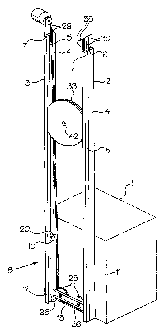
Contrepoids d'ascenseur consistant en un disque monté de manière à glisser sur des rails dans une gaine d'ascenseur. Des gorges circulaires autour du disque reçoivent des câbles qui sont ancrés au sommet de la gaine, et de prolongent autour de poulie sur l'arrière d'une cabine, et un réa entraîné par un moteur réversible; lorsque le moteur est mis en marche, l'ascenseur se déplace verticalement dans une direction, alors que le contrepoids tourne et se déplace verticalement dans la direction opposée.


Abrégé anglais

A counterweight for an elevator is defined by a disc, which can be slidably mounted in tracks in an elevator shaft. Annular grooves in the periphery of the disc receive cables, which are anchored at the top of the shaft, and extend around pulleys on the rear of a car and a sheave driven by a reversible motor, whereby when the motor is actuated, the elevator moves vertically in one direction, while the counterweight rotates and moves vertically in the opposite direction.

Revendications

Note : Les revendications sont présentées dans la langue officielle dans laquelle elles ont été soumises.


THE EMBODIMENTS OF THE INVENTION IN WHICH AN EXCLUSIVE
PROPERTY OR PRIVILEGE IS CLAIMED ARE DEFINED AS FOLLOWS:
1. A counterweight for an elevator comprising a disc for sliding in an
elongated track; and at least one annular groove extending around the
periphery of
said disc for receiving and guiding a support cable.
2. A counterweight according to claim 1, including at least two annular
grooves extending around the periphery of the disc for receiving a plurality
of
support cables.
3. A counterweight system for an elevator, which includes a car slidably
mounted on a pair of elongated, first tracks for vertical movement in an
elevator
shaft, said system comprising a pair of parallel second tracks; a disc-shaped
counterweight for slidable mounting in said second tracks; a car pulley
rotatably
mounted on said car; at least one cable for movably supporting said car and
said
counterweight for movement in said first and second tracks; said cable having
two
ends fixed at a location proximate top ends of one of said first and second
tracks, a
drive pulley at a location proximate the top ends of the other said first and
second
tracks; and a reversible motor connected to said drive pulley, said cable
extending
around and supporting said counterweight, said drive pulley and said car
pulley,
whereby, when said motor is actuated, said car is caused to move vertically in
one
direction and said counterweight moves vertically in the opposite direction.
4. An elevator assembly comprising a pair of first elongated, parallel
tracks for mounting in an elevator shaft; a car slidably mounted on said first
tracks
for vertical movement in an elevator shaft, a pair of parallel second tracks;
a disc-
shaped counterweight for slidable mounting in said second tracks; a car pulley
7

rotatably mounted on said car; at least one cable for movably supporting said
car
and said counterweight for movement in said first and second tracks; said
cable
having two ends fixed at a location proximate top ends of one of said first
and
second tracks, a drive pulley at a location proximate the top ends of the
other said
first and second tracks; and a reversible motor connected to said drive
pulley, said
cable extending around and supporting said counterweight, said drive pulley
and
said car pulley, whereby, when said motor is actuated, said car is caused to
move
vertically in one direction and said counterweight mover vertically in the
opposite
direction.
8

Description

Note : Les descriptions sont présentées dans la langue officielle dans laquelle elles ont été soumises.


CA 02414748 2002-12-19
This invention relates to an elevator counterweight and to a system
incorporating the counterweight for use in an elevator.
The use of counterweights is common to most elevators in which the elevator
car is lifted by means of cables. Examples of such counterweights or elevator
systems using counterweights are described in US Patents Nos. 610,481, issued
to
E.M. Fraser on September 6, 1898; 5,429,211, issued to E. Aulanko et al on
July 4,
1995; 5,435,417, issued to H. Hakala on July 25, 1995; 5,469,937, issued to H.
Hakala et al on November 28, 1995; 5,566,785, issued to H. Hakala on October
22,
1996; 5,573,084, issued to H. Hakala on November 12, 1996; 5,901,814, issued
to
L. Adifon et al on May 11, 1999; 5,984,052, issued to J-N. Cloux et al on
November
16, 1999; 6,068,087, issued to R. Moncini on May 30, 2000, and laid open
Application No. 2001/0009210 filed by K. Kobayashi et al on March 26, 2001.
Conventional counterweights almost invariably include multiple steel or cast
iron weights clamped directly to elevator cables or suspended from the cables
for
rolling or sliding along a set of guide rails on one side of an elevator
shaft. The rails
are usually T-shaped, and if the weights slide on the rails, then the rails
must be
lubricated on a regular basis. If the counterweight is equipped with guide
rollers, the
usual number per counterweight is twelve, with three rollers bearing on each
side of
the T-shaped rail at each corner of the counterweight assembly. Moreover,
conventional counterweight assemblies require elevator shafts having a large
area.
An object of the present invention is to provide a relatively simple
counterweight and an elevator and counterweight assembly which eliminate the
need for guide rollers, thus reducing a large number of components such as
shafts,
bearings and mounting brackets required in conventional systems. The reduction
of
1

CA 02414748 2002-12-19
components reduces the failure potential inherent in such components.
According to one aspect, the invention relates to a counterweight for an
elevator comprising a disc-shaped body for sliding in elongated tracks; and at
least
one annular groove extending around the periphery of said body for receiving
and
guiding a support cable.
According to another aspect, the invention relates to a counterweight system
for an elevator, which includes a car slidably mounted on a pair of elongated,
first
tracks for vertical movement in an elevator shaft, said system comprising a
pair of
parallel second tracks; a disc-shaped counterweight for slidable mounting in
said
second tracks; a car pulley rotatably mounted on said car; at least one cable
for
movably supporting said car and said counterweight for movement in said first
and
second tracks; said cable having two ends fixed at a location proximate top
ends of
one of said first and second tracks, a drive pulley at a location proximate
the top
ends of the other said first and second tracks; and a reversible motor
connected to
said drive pulley, said cable extending around and supporting said
counterweight,
said drive pulley and said car pulley, whereby, when said motor is actuated,
said car
is caused to move vertically in one direction and said counterweight moves
vertically
in the opposite direction.
The invention also relates to an elevator assembly comprising a pair of first
elongated, parallel tracks for mounting in an elevator shaft; a car slidably
mounted
on said first tracks for vertical movement in an elevator shaft, a pair of
parallel
second tracks; a disc-shaped counterweight for slidable mounting in said
second
tracks; a car pulley rotatably mounted on said car; at least one cable for
movably
supporting said car and said counterweight for movement in said first and
second
2

CA 02414748 2002-12-19
tracks; said cable having two ends fixed at a location proximate top ends of
one of
said first and second tracks, a drive pulley at a location proximate the top
ends of
the other said first and second tracks; and a reversible motor connected to
said drive
pulley, said cable extending around and supporting said counterweight, said
drive
pulley and said car pulley, whereby, when said motor is actuated, said car is
caused
to move vertically in one direction and said counterweight moves vertically in
the
opposite direction.
The use of a hanging disc-shaped counterweight requires only simple loose
fitting, C-shaped guide rails, which need little or no lubrication and no
maintenance.
The motion of the counterweight rising and falling in the opposite direction
to the
elevator car is a very slow rotation of one or two revolutions while sliding
up or down
in the guide rails. For safety reasons, in an elevator assembly intended to
carry
people, at least two cables will be used. However, the counterweight design of
the
present invention allows for the use of a plurality of cables - up to five,
six or more -
depending upon the load carrying requirements and the intended use of the
elevator. Because the counterweight moves relatively slowly, the whole
elevator
assembly is quiet.
The invention is described below with reference to the accompanying
drawings, wherein:
Figure 1 is a schematic, isometric view of an elevator and a counterweight
system in accordance with the invention;
Figure 2 is a schematic, isometric view of an elevator car used with the
counterweight of Fig. 1;
Figure 3 is a cross section taken generally along line 3-3 of Fig. 2;
3

CA 02414748 2010-01-12
01/12/2010 14:25 FAX 6132325831 SEABY & ASSOCIATES Z003
Figure 4 is a cross-sectional view of a counterweight used in the system of
Fig. 1, and
Figure 5 is a schematic, isometric view of the counterweight system of Fig. 1
III
with parts omitted.
Referring to Fig. 1, the counterweight system of the present invention.is
intended for use with a conventional elevator including a car 1, which is
mounted in
a shaft (not shown) for vertical movement therein. The car I is slidably
mounted on
a pair of parallel tracks 2 and 3 extending substantially the entire length of
the shaft.
Each of the tracks 2 and 3 is defined by a pair of elongated metal beams 4 and
5
which have.generally C-shaped cross sections, the open sides of the beams
facing
each other. The beams 4 and 5 define tracks or channels 6 and 7.
A carriage indicated generally at 8 (Fig. 2) slidably supports the car 1 in
the
tracks 2 and 3. The carriage 8 is defined by a pair of parallel, vertically
extending
beams 10 mounted on the rear wall 11 of the car 1. The beams 10 are L-shaped
in
cross section, the free end of the long arm of the L being connected to the
car 1 and
the open sides of the beams facing outwardly. The long arm of each beam 10 is
connected to the rear wall 11 of the car 10. A crossbar 13 extends between the
bottom ends of the beams 10. Stepped bottom rollers 15 in the beams 10 ride on
the outside walls 16 (Fig. 3) of the channels 6. The rollers 15 are offset
with respect
to the longitudinal centerline of the beams 10 and extend through cutouts 17
(Fig. 2)
in the outside arms of the beams 10 to ride on the outer walls 16 of the track
beams
4. Top rollers 20, which are offset on the other sides of the centerlines of
the beams
10, ride on the inner walls 21 (Fig. 3) of the track beams 4. The rollers 15
and 20
are supported by stub axles 22 and 23, respectively in the beams 10.
4
PAGE 315 RCVD AT 111212010 2:31:14 PM [Eastern Standard Time]' SVR:F00003111 I
DNIS:3907 C$ID:6132325831 * DURATION (mm=ss):00.35

CA 02414748 2002-12-19
A pair of spaced apart pulleys 25 are mounted on bearings 26 in the crossbar
13. A pair of annular grooves 28 in each pulley 25 receive cables 29. As shown
schematically in Fig. 5, a first end 30 of each cable 29 is fixed securely to
the top of
the elevator shaft. The cables 29 extend downwardly in the channel 6 of one
track 2
around the bottom of the pulleys 25, upwardly around a drive sheave 32 mounted
in
the elevator shaft above the top end of the track 3, downwardly around a
counterweight 33 and upwardly to the location of the first end 30 of the
cable. The
second end 35 of each cable 29 is fixed to the elevator shaft at the same
location as
the first end 30 of the cable. The sheave 32 is driven by a reversible
electric motor
36.
With particular reference to Fig. 4, the counterweight 33 is in effect a large
sheave defined by a large disc-shaped, metal body 38 with a pair of generally
U-
shaped grooves 39 extending around the periphery 40 thereof for receiving the
cables 29. The cables 29 are held securely in the grooves 39, whereby movement
of the cables 29 causes rotation of the counterweight 33. The body 38 is
slidably
mounted in the channels 7 of the opposed, parallel tracks 2 and 3. A hole 42
is
provided in the center of the body 38 for receiving a bolt (not shown) which
can be
used to attach additional weights to the counterweight.
The counterweight 33 can have several different design variations. For
example, the body 38 can include an outer grooved steel rim for accommodating
the
cables, with both sides covered with steel plates to form a housing, which can
be
filled with concrete construction, e.g. through a hole in one of the plates
covered by
a steel cover. Steel shot or depleted iron ore could also be used to fill the
hollow
body of the counterweight.
5

CA 02414748 2002-12-19
In yet another alternative, the body 38 can be formed of two or more discs,
all
having suitable grooves and counter-rotating on a center pivot or bearing to
provide
more widely spaced lifting points for an elevator car of greater length, as in
a
hospital or freight elevator. In an elevator car of greater length, the cables
29 are
slung directly under the car from anchor points on the side of the elevator
shaft
opposite the counterweights and the hoisting motor 36 and drive sheaves 32.
In situations where space is a problem, the counterweights can be located in
a part of a building separate from the elevator shaft containing the car. The
counterweights would be connected to the elevator car and the anchor points
using
longer cables and appropriately positioned guide sheaves. Moreover, the
counterweight 33 can be "roped" in such a manner that it travels only one half
the
distance traveled by the car.
Finally, with the addition of a simple bridle to roller pinch the cables 40
above
the counterweight center and an additional small weight below the center of
gravity
of the counterweight, the latter could hang freely with no C-channels to guide
it. For
safety reasons, the free space would have to be suitably protected to prevent
unauthorized access.
6

Dessin représentatif
Une figure unique qui représente un dessin illustrant l'invention.
États administratifs

2024-08-01 : Dans le cadre de la transition vers les Brevets de nouvelle génération (BNG), la base de données sur les brevets canadiens (BDBC) contient désormais un Historique d'événement plus détaillé, qui reproduit le Journal des événements de notre nouvelle solution interne.

Veuillez noter que les événements débutant par « Inactive : » se réfèrent à des événements qui ne sont plus utilisés dans notre nouvelle solution interne.

Pour une meilleure compréhension de l'état de la demande ou brevet qui figure sur cette page, la rubrique Mise en garde , et les descriptions de Brevet , Historique d'événement , Taxes périodiques et Historique des paiements devraient être consultées.

Historique d'événement

Description Date
Le délai pour l'annulation est expiré 2022-06-21
Lettre envoyée 2021-12-20
Lettre envoyée 2021-06-21
Lettre envoyée 2020-12-21
Représentant commun nommé 2019-10-30
Exigences relatives à la nomination d'un agent - jugée conforme 2019-10-01
Exigences relatives à la révocation de la nomination d'un agent - jugée conforme 2019-10-01
Inactive : Lettre officielle 2019-09-19
Demande visant la nomination d'un agent 2019-08-29
Demande visant la révocation de la nomination d'un agent 2019-08-29
Inactive : TME en retard traitée 2017-06-05
Lettre envoyée 2016-12-19
Accordé par délivrance 2011-07-05
Inactive : Page couverture publiée 2011-07-04
Un avis d'acceptation est envoyé 2011-05-03
Inactive : Approuvée aux fins d'acceptation (AFA) 2011-03-22
Lettre envoyée 2011-02-01
Taxe finale payée et demande rétablie 2010-12-02
Requête en rétablissement reçue 2010-12-02
Inactive : Taxe finale reçue 2010-12-02
Retirer de l'acceptation 2010-12-02
Préoctroi 2010-12-02
Réputée abandonnée - les conditions pour l'octroi - jugée non conforme 2010-10-14
Lettre envoyée 2010-04-14
Un avis d'acceptation est envoyé 2010-04-14
Inactive : Approuvée aux fins d'acceptation (AFA) 2010-03-31
Modification reçue - modification volontaire 2010-01-12
Inactive : Dem. de l'examinateur art.29 Règles 2009-11-19
Inactive : Dem. de l'examinateur par.30(2) Règles 2009-11-19
Lettre envoyée 2008-01-09
Toutes les exigences pour l'examen - jugée conforme 2007-12-11
Exigences pour une requête d'examen - jugée conforme 2007-12-11
Requête d'examen reçue 2007-12-11
Inactive : CIB de MCD 2006-03-12
Demande publiée (accessible au public) 2004-06-19
Inactive : Page couverture publiée 2004-06-18
Inactive : CIB en 1re position 2003-02-19
Inactive : Certificat de dépôt - Sans RE (Anglais) 2003-02-04
Demande reçue - nationale ordinaire 2003-02-04
Déclaration du statut de petite entité jugée conforme 2002-12-19

Historique d'abandonnement

Date d'abandonnement Raison Date de rétablissement
2010-12-02
2010-10-14

Taxes périodiques

Le dernier paiement a été reçu le 2010-12-02

Avis : Si le paiement en totalité n'a pas été reçu au plus tard à la date indiquée, une taxe supplémentaire peut être imposée, soit une des taxes suivantes :

  • taxe de rétablissement ;
  • taxe pour paiement en souffrance ; ou
  • taxe additionnelle pour le renversement d'une péremption réputée.

Les taxes sur les brevets sont ajustées au 1er janvier de chaque année. Les montants ci-dessus sont les montants actuels s'ils sont reçus au plus tard le 31 décembre de l'année en cours.
Veuillez vous référer à la page web des taxes sur les brevets de l'OPIC pour voir tous les montants actuels des taxes.

Historique des taxes

Type de taxes Anniversaire Échéance Date payée
Taxe pour le dépôt - petite 2002-12-19
TM (demande, 2e anniv.) - petite 02 2004-12-20 2004-12-13
TM (demande, 3e anniv.) - petite 03 2005-12-19 2005-12-08
TM (demande, 4e anniv.) - petite 04 2006-12-19 2006-12-19
Requête d'examen - petite 2007-12-11
TM (demande, 5e anniv.) - petite 05 2007-12-19 2007-12-11
TM (demande, 6e anniv.) - petite 06 2008-12-19 2008-10-23
TM (demande, 7e anniv.) - petite 07 2009-12-21 2009-12-14
Taxe finale - petite 2010-12-02
Rétablissement 2010-12-02
TM (demande, 8e anniv.) - petite 08 2010-12-20 2010-12-02
TM (brevet, 9e anniv.) - petite 2011-12-19 2011-12-13
TM (brevet, 10e anniv.) - petite 2012-12-19 2012-12-18
TM (brevet, 11e anniv.) - petite 2013-12-19 2013-11-04
TM (brevet, 12e anniv.) - petite 2014-12-19 2014-11-24
TM (brevet, 13e anniv.) - petite 2015-12-21 2015-12-17
Annulation de la péremption réputée 2016-12-19 2017-06-05
TM (brevet, 14e anniv.) - petite 2016-12-19 2017-06-05
TM (brevet, 15e anniv.) - petite 2017-12-19 2017-11-21
TM (brevet, 16e anniv.) - petite 2018-12-19 2018-10-24
TM (brevet, 17e anniv.) - petite 2019-12-19 2019-12-19
Titulaires au dossier

Les titulaires actuels et antérieures au dossier sont affichés en ordre alphabétique.

Titulaires actuels au dossier
HAROLD H. HAYNES
Titulaires antérieures au dossier
S.O.
Les propriétaires antérieurs qui ne figurent pas dans la liste des « Propriétaires au dossier » apparaîtront dans d'autres documents au dossier.
Documents

Pour visionner les fichiers sélectionnés, entrer le code reCAPTCHA :


Pour visualiser une image, cliquer sur un lien dans la colonne description du document (Temporairement non-disponible). Pour télécharger l'image (les images), cliquer l'une ou plusieurs cases à cocher dans la première colonne et ensuite cliquer sur le bouton "Télécharger sélection en format PDF (archive Zip)" ou le bouton "Télécharger sélection (en un fichier PDF fusionné)".

Liste des documents de brevet publiés et non publiés sur la BDBC .

Si vous avez des difficultés à accéder au contenu, veuillez communiquer avec le Centre de services à la clientèle au 1-866-997-1936, ou envoyer un courriel au Centre de service à la clientèle de l'OPIC.

({010=Tous les documents, 020=Au moment du dépôt, 030=Au moment de la mise à la disponibilité du public, 040=À la délivrance, 050=Examen, 060=Correspondance reçue, 070=Divers, 080=Correspondance envoyée, 090=Paiement})


Description du
Document 
Date
(aaaa-mm-jj) 
Nombre de pages   Taille de l'image (Ko) 
Abrégé 2002-12-18 1 15
Description 2002-12-18 6 285
Revendications 2002-12-18 2 70
Dessins 2002-12-18 4 79
Dessin représentatif 2003-03-18 1 7
Description 2010-01-11 6 279
Dessins 2010-01-11 4 76
Dessin représentatif 2011-06-02 1 8
Certificat de dépôt (anglais) 2003-02-03 1 159
Rappel de taxe de maintien due 2004-08-22 1 110
Rappel - requête d'examen 2007-08-20 1 119
Accusé de réception de la requête d'examen 2008-01-08 1 176
Avis du commissaire - Demande jugée acceptable 2010-04-13 1 166
Courtoisie - Lettre d'abandon (AA) 2011-01-05 1 165
Avis de retablissement 2011-01-31 1 170
Avis concernant la taxe de maintien 2017-01-29 1 178
Avis concernant la taxe de maintien 2017-01-29 1 179
Quittance d'un paiement en retard 2017-06-04 1 163
Avis du commissaire - Non-paiement de la taxe pour le maintien en état des droits conférés par un brevet 2021-02-07 1 545
Courtoisie - Brevet réputé périmé 2021-07-11 1 549
Avis du commissaire - Non-paiement de la taxe pour le maintien en état des droits conférés par un brevet 2022-01-30 1 542
Paiement de taxe périodique 2018-10-23 1 25
Taxes 2004-12-12 1 23
Taxes 2005-12-07 1 24
Taxes 2006-12-18 1 24
Taxes 2007-12-10 1 28
Taxes 2008-10-22 1 23
Taxes 2010-12-01 1 39
Correspondance 2010-12-01 1 39
Taxes 2013-11-03 1 23
Taxes 2014-11-23 1 25
Taxes 2015-12-16 1 25
Paiement de taxe périodique 2017-06-04 1 26
Paiement de taxe périodique 2017-11-20 1 25
Courtoisie - Lettre du bureau 2019-09-18 1 35