Sélection de la langue

Search

Sommaire du brevet 2416310 

Énoncé de désistement de responsabilité concernant l'information provenant de tiers

Une partie des informations de ce site Web a été fournie par des sources externes. Le gouvernement du Canada n'assume aucune responsabilité concernant la précision, l'actualité ou la fiabilité des informations fournies par les sources externes. Les utilisateurs qui désirent employer cette information devraient consulter directement la source des informations. Le contenu fourni par les sources externes n'est pas assujetti aux exigences sur les langues officielles, la protection des renseignements personnels et l'accessibilité.

Disponibilité de l'Abrégé et des Revendications

L'apparition de différences dans le texte et l'image des Revendications et de l'Abrégé dépend du moment auquel le document est publié. Les textes des Revendications et de l'Abrégé sont affichés :

  • lorsque la demande peut être examinée par le public;
  • lorsque le brevet est émis (délivrance).
(12) Demande de brevet: (11) CA 2416310
(54) Titre français: METHODE ET DISPOSITIF DE MESURE DES CONCENTRATIONS
(54) Titre anglais: A METHOD AND A DEVICE FOR MEASURING OF CONCENTRATIONS
Statut: Réputée abandonnée et au-delà du délai pour le rétablissement - en attente de la réponse à l’avis de communication rejetée
Données bibliographiques
(51) Classification internationale des brevets (CIB):
  • G01N 1/38 (2006.01)
  • D21H 23/78 (2006.01)
  • G01N 11/08 (2006.01)
  • G01N 33/34 (2006.01)
(72) Inventeurs :
  • FLADDA, GERDT (Suède)
  • WENG, JONNY (Suède)
(73) Titulaires :
  • BTG KALLE INVENTING AB
(71) Demandeurs :
  • BTG KALLE INVENTING AB (Suède)
(74) Agent: SMART & BIGGAR LP
(74) Co-agent:
(45) Délivré:
(22) Date de dépôt: 2003-01-16
(41) Mise à la disponibilité du public: 2003-07-25
Requête d'examen: 2007-11-14
Licence disponible: S.O.
Cédé au domaine public: S.O.
(25) Langue des documents déposés: Anglais

Traité de coopération en matière de brevets (PCT): Non

(30) Données de priorité de la demande:
Numéro de la demande Pays / territoire Date
0200221-0 (Suède) 2002-01-25

Abrégés

Abrégé anglais


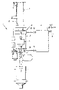
The invention relates to a method and a device for measur-
ing concentrations especially in a pulp suspension, from
which a sample (3) has been taken. The sample (3) is
collected in a measuring vessel (2), in which a piston (6)
is guided upwards and downwards in order to press the
sample (3) from each direction through a measuring sensor
(5) connected at the side of the measuring vessel via com-
municating tubes (4,4') connected in an upper and an lower
position to the measurement vessel (2), whereby the sample
(3) is stirred totally for eliminating of a flocculation
in the same, whereupon a measurement of the concentration
of the sample (3) is made either during the movement
upwards or downwards of the piston (6) in the measuring
vessel (2) and first when the speed of the sample (3)
through the measuring sensor (5) is constant and the
sample has been homogenized at least after some movement
upwards and downwards of the piston. The device consists
of a sample treatment unit (1), in which communicating
tubes (4,4') connect the upper (10) and lower (10') por-
tion of a measuring sensor (5), in said measuring vessel a
piston (6) is guidable upwards and downwards to press the
sample (3) through the measuring sensor (5) from each
direction and said diameter of said piston (6) mainly
corresponds to the inner contour of the measuring vessel
(2), the flow rate of the sample being controllable via
the speed of the piston and the measurement of the
concentration of the sample is practicable both during the
movement upwards and downwards of the piston (6).

Revendications

Note : Les revendications sont présentées dans la langue officielle dans laquelle elles ont été soumises.


8
Claims
1. A method for measuring concentration especially
in a pulp suspension, from which a example has been taken,
characterized in that the sample (3) is collected in a
measuring vessel (2), in which a piston (6) is guided
upwards and downwards in order to press said sample (3)
from each direction through a measuring sensor (5)
connected at the side of the measuring vessel via com-
municating tubes (4,4') connected in an upper and lower
position to the measuring vessel (2), whereby the sample
(3) is stirred totally for eliminating of a flocculation
in the same, whereupon a measurement of the concentration
of the sample (3) is made either during the movement
upwards or downwards of the piston (6) in the measuring
vessel (2) and only when the speed of the sample (3)
through the measuring sensor (5) is constant and the
sample (3) has been homogenized at least after some
movement upwards and downwards of the piston.
2. A method according to claim 1, characterized in
that the sample (3) is subjected to a strong turbulent
formation during its pressing by aid of the piston
laterally into the communicating tubes (4,4') locataed at
the upper- and underside of the measuring vessel (2),
respectively.
3. A method according to claim 1, characterized in
that the sample (3) is deaerated before the measurement of
the concentration via at least one deaeration pipe (8)
provided on the upper side of the measuring vessel (2).
4. A method according to cloaim 1, characterized in
that the sample (3) in actual cases is diluted with clean

9
water from a vessel (11) which is provided in parallel
with the measuring vessel (2) and communicates via valves
(12,13).
5. A device for measuring concentrations especially
in a pulp suspension, from which a sample (3) has been
taken and including a measuring vessel (2) for collecting
the same, characterized in that the measuring vessel (2)
is included in a sample treatment unit (1), which via
communicating tubes (4,4') connect the upper (10) and
lower portion (10') of the measuring vessel to a measuring
sensor (5), in which a piston (6) is guidable upwards and
downwards in order to press the sample (3) through the
measuring sensor (5) from each direction and said diameter
of said piston (6) mainly corresponds to the inner contour
of the measuring vessel (2), the flow rate of the sample
(3) being controllable via the speed of the piston (6) and
the measurement of the concentration of the sample is
practicable both during the movement upwards and downwards
of the piston (6), said measurement is taking place not
until the speed of the sample (3) through the measuring
sensor (5) is constant and has been homogenized.
6. A device according to claim 5, characterized in
that measuring vessel (2) has the form of a cylinder
having a diameter which mainly corresponds to the diameter
of the displaceable piston (6) in the measuring vessel.
7. A device according to claim 5 or 6, characterized
in that the upper portion (10) of the measuring vessel (2)
has a larger inner diameter than the rest of the same in
order to make a passage of air bubbles in a column (14)
possible passed the piston and up to an deaeration pipe
(8) located on the measuring vessel.

10
8. A device according to claim 5, characterized in
that the measuring vessel (2) has a dilution vessel (11)
with clean water provided in parallel with the same, said
vessel (11) communicates with the measuring vessel at the
top and at the bottom with tubes (15,16) via valves
(12,13).

Description

Note : Les descriptions sont présentées dans la langue officielle dans laquelle elles ont été soumises.


CA 02416310 2003-O1-16
1
A method and a device for measuring concentrations
The present invention refers to a method and a device for
measuring concentrations preferably in pulp suspensions.
Better control over processes in manufacturing industry is
one solution in order to obtain a better productivity,
better and new qualities and le:~s influence on the
surroundings. Therefore measuring on-line is absolutely a
necessity. The measurement shows the connections between
the process, the raw material and the finished product and
gives an increased understanding for the dynamic of the
process and with that a basis for taking up more effective
control strategies. Measuring on-line can be done in
different ways depending on the measuring method and the
measuring sequence required. One method is measuring in-
line where the measuring sensor is directly mounted in the
measuring medium, e.g. a temperature sensor. However,
specific measuring' parameters often have to be determined
on samples taken out from the measuring medium. One reason
for this is that the sample before the measuring procedure
e.g. has to be diluted to lower concentrations or be pre
treated in another way, for example pH-adjusting, de
airation, dosing of chemicals in order to initiate certain
reactions, which thereafter shall be measured etc.
Within pulp- and paper industry concentration measuring on
pulp suspensions is of a central importance. These sus-
pensions often contain not only wood fibres but also
different fill agents such as clay, calcium carbonate etc.
and various chemicals for example for bleaching of the
fibres or flock formation between the different suspended
substances. Dependent on the measuring position the con-
centration can vary between one tenth of a procent and ten

CA 02416310 2003-O1-16
2
procent. In certain measuring posit~_ons it is extra im-
portant to obtain accurate results on the total concen-
tration of fibres inclusive filler, and also on only
filler. An in-line meter cannot always give such an
information. This can depend on the state of the sus-
pension and/or on the actual design of the method, which
is not suitable to base an in-line sensor upon.
For concentration measuring optical measuring principles
are often used, especially when differentiated information
concerning the composition of the suspension with respect
to different suspended materials, shall be obtained. Optic
concentration measuring is among other things sensitive
for air bubbles in the suspension and flock formation.
Flocks constitute "large particles" of many small and give
an incorrect measurement signal information. In situations
having among other things the criteries mentioned above a
special sample treatment equipment is used in order to
obtain a satisfactory results. The equipment normally
consists of a measuring vessel having an integrated pump
loop, in which the measuring sensor is placed. The
principle function is as follows: Via a sampling valve a
separate pulp sample is fed to the measuring vessel and is
thereafter pumped around a certain time before the
measuring is made. The pumping around of the sample before
the measuring is needed so that the sample shall be de-
aired and de-flocculated. After the measurement the sample
is drained from the measuring vessel to the outlet and the
next measuring cycle is started in that a new sample is
taken. Between a number of measurements the whole sample
treatment unit can be cleaned by water distributors and
filling up with clean water. Besides a measurement can be
done on the clean water in order to zero point calibrate
the optical measuring system. At too high concentrations

CA 02416310 2003-O1-16
3
the optical measuring principle does not function satis-
factory and there is in this case a risk that the
measuring cell is plugged by the pulp. Therefore, the
sample, when needed, be diluted with clean water. The
dilution is controlled via level guards in the measuring
vessel.
The conventional method which is here described for a
sample treatment unit in connection with for example an
optical concentration determination of pulp suspensions
functions on the whole. However, there are evident limi-
tations and/or drawbacks:
~ For the task a relatively big, expensive and energy
requiring pump is needed, which besides must be
rotation speed regulated in order to obtain a suit-
able flow rate for the measurement through the
measuring transducer and for control of the de-
aeration. A too high rotation speed instead can
create a vortex formation in the measuring vessel, so
that air is sucked into the suspension.
~ The tightening between the motor axle and the pump
housing becomes easily untight and relatively often
has to be changed. The untightness means that air can
be sucked into the suspension, which shall be mea-
sured, which spoils the measurement.
~ The fibres of. the pulp suspension in the pump housing
can be broken or in another wa.y be changed, so that
the measuring results can be wrong. Furthermore,
during high rotation speeds in the pump housing cavi-
tation effects can easily arise, so that disturbing

CA 02416310 2003-O1-16
4
air bubbles are created. Dependent on the structure
the pump housing can also be difficult to be de-
aerated at the time of each new measurement cycle.
~ A pump based sample treatment unit requires a rela-
tively large measuring vessel. The size of the
measuring vessel is directly related to the de-
aeration- and deflocculation time and to that time it
takes to homogenize the sample, especially when di -
luted, which is of great importance for the quality
of the measurement. Prolonged times also mean that
the total time for a whole measurement sequence is
prolonged, so that the measurement frequency is too
low in order to receive a good control information
for an effective process control.
The object of the present invention is to provide a new
type of sample treatment unit, which eliminates the
drawbacks stated above, which exist in a pump based
system. The features characterizing the invention appear
from the subsequent patent claims.
Thanks to the invention there do now exist a method and a
device for measurement of concentration of especially pulp
suspensions, said device is essentially cheaper, simpler
in its structure, more reliable in running and has a
larger efficiency concerning stirring/homogenizing, de-
aearation and deflocculation. All l~his gives a quicker,
better and run-safer measuring information.
The invention will now be described in more detail below
by aid of a preferred embodiment example with reference to
the drawings enclosed, on which

CA 02416310 2003-O1-16
Fig. 1 illustrates a side-view of a sample treatment
unit according to the invention, having a
connected vessel for dilution of the measuring
sample with clean water,
5
Fig. 2 illustrates the sample treatment unit in Fig. 1
turned 90° without the connected vessel for
dilution of the measurement sample and
Fig. 3 is a schematic side-view of the measuring vessel
of the sample treatment unit. having its piston in
its upper position.
As can be seen from the draw~_ngs the invention refers to a
device in the form of a sample treatment unit l, whi_Ch is
based on a closed measuring vessel 2, which is filled
completely with a measuring sample 3. At the side of the
measuring vessel 2, which in the example illustrated is
cylinderformed, communicating tubes 4 and 4' are provided,
which connect the upper part 10 and the lower part 10' of
the measuring vessel 2 to a measuring sensor 5. A piston 6
is guided upwards and downwards in the measuring vessel 2
via a pressure air cylinder 7, so that the measuring
sample 3 is pressed through the measuring sensor 5 from
each direction. The diameter of the ciston 6 is mainly the
same as the inner diameter of the measuring vessel 2. The
flow rate is in a simple way controlled via the speed of
the piston 6, which in its turn s_s controlled via the
pressure of the used pressurized air, regulated by aid of
a pressure reducing wave. The measurement can be done both
during the movement upwards and downwards of the piston 6
and is made only when the speed of the sample 3 through
the measuring sensor 5 is constant and the sample 3 at
least after some movement upwards or downwards of the

CA 02416310 2003-O1-16
6
piston 6, has been homogenized. The arrangement of the
measuring vessel and the piston gives a 1000 movement or
transport of the total measuring volume of the taken
sample and a quick and effective stirring and defloc-
culation of the sample, so that a representative measure-
ment sample can be supplied to the sensor for the measure-
ment. Furthermore the transport of the measuring sample 3
cannot provide any changement of the fibres of the
measurement suspension, which in a contrast hereto can be
the case using a pump according to the prior art described
above. Stirring and deflocculation is provided according
to the invention by a strong turbulent formation, when the
sample 3 at the lower- and upper :>ide of the measuring
vessel 2, respectively, is pressed into the communicating
tubes 4,4' located at the side of said measuring vessel 2,
which includes the measuring sensor 5. The deaeration of
the measuring sample 3 occurs via an deaeration pipe 8
mounted to the upper side of the measuring vessel 2. The
upper part 20 of the measuring vessel 2 is provided with
larger, inner diameter than the rest of the same, so that
air bubbles can move upwards and disappear through the
deaearation pipe 8, whereby air bubbles can pass the
piston 6, when it is in its uppermost position. During
filling of the measuring vessel 2 with the sample 3 the
piston 6 is normally in its uppermost position, so that an
immediate deaearation shall take place, however, also so
that the measuring vessel 2 totally can be filled with the
pulp suspension. A Level sensor at the deaearation pipe
indicates that the measuring vessel. 2 is filled up and
that the in-flow of the measuring sample 3 in this case
can be stopped, so that thereafter the measuring sequence
can be started.

CA 02416310 2003-O1-16
7
Another advantage with the unit according to the invention
is that plugging of the measuring sensor 5, which normally
has a smaller feecLing flow area than the area of the com-
municating tubes 4 and 4' on the side of the measuring
vessel, easily can be prevented by turning the movement
direction of the piston 6, so that the °°mass plug'° both
can be sucked and pressed °°in righi~ direction" out from
the sensor opening. A plugging of the measuring sensor 5
is indicated in a simpler way via tr.e speed change of the
piston 6 and/or via a built-in pressure transmitter. The
speed of the piston 6 can be calcu=Lated via the time it
takes to move the pneumatic cylinder 7, which is used for
control of the piston 6 from the one to the other end
position. This movement or displacement is indicated by
aid of an end position sensor, which is used in order to
change direction of the piston during the movement of the
same in an upward and downward direcaion. For dil ution of
measuring sample 3 a communicating vessel 11 containing
clean water is used in parallel wits. the measuring vessel
2. This di1_ution vessel 11 is via valves 12,13 and pipes
15,16 connected to the measuring vessel 2. If both the
upper and the under valves 15 and 7_6 are opened the un
diluted sample is mixed quickly and effectively with the
water, especially if the dilution vessel 11 is not bigger
in its volume than the measuring vessel 2.

Dessin représentatif
Une figure unique qui représente un dessin illustrant l'invention.
États administratifs

2024-08-01 : Dans le cadre de la transition vers les Brevets de nouvelle génération (BNG), la base de données sur les brevets canadiens (BDBC) contient désormais un Historique d'événement plus détaillé, qui reproduit le Journal des événements de notre nouvelle solution interne.

Veuillez noter que les événements débutant par « Inactive : » se réfèrent à des événements qui ne sont plus utilisés dans notre nouvelle solution interne.

Pour une meilleure compréhension de l'état de la demande ou brevet qui figure sur cette page, la rubrique Mise en garde , et les descriptions de Brevet , Historique d'événement , Taxes périodiques et Historique des paiements devraient être consultées.

Historique d'événement

Description Date
Inactive : CIB expirée 2024-01-01
Demande non rétablie avant l'échéance 2012-09-24
Inactive : Morte - Aucune rép. dem. par.30(2) Règles 2012-09-24
Réputée abandonnée - omission de répondre à un avis sur les taxes pour le maintien en état 2012-01-16
Inactive : Abandon. - Aucune rép dem par.30(2) Règles 2011-09-23
Inactive : Dem. de l'examinateur par.30(2) Règles 2011-03-23
Lettre envoyée 2008-01-02
Modification reçue - modification volontaire 2007-11-30
Requête d'examen reçue 2007-11-14
Exigences pour une requête d'examen - jugée conforme 2007-11-14
Toutes les exigences pour l'examen - jugée conforme 2007-11-14
Inactive : CIB de MCD 2006-03-12
Demande publiée (accessible au public) 2003-07-25
Inactive : Page couverture publiée 2003-07-24
Lettre envoyée 2003-03-14
Inactive : CIB en 1re position 2003-03-13
Inactive : CIB attribuée 2003-03-13
Inactive : Correspondance - Transfert 2003-03-04
Inactive : Lettre de courtoisie - Preuve 2003-02-25
Demande reçue - nationale ordinaire 2003-02-18
Exigences de dépôt - jugé conforme 2003-02-18
Inactive : Certificat de dépôt - Sans RE (Anglais) 2003-02-18
Inactive : Transfert individuel 2003-02-10

Historique d'abandonnement

Date d'abandonnement Raison Date de rétablissement
2012-01-16

Taxes périodiques

Le dernier paiement a été reçu le 2010-12-31

Avis : Si le paiement en totalité n'a pas été reçu au plus tard à la date indiquée, une taxe supplémentaire peut être imposée, soit une des taxes suivantes :

  • taxe de rétablissement ;
  • taxe pour paiement en souffrance ; ou
  • taxe additionnelle pour le renversement d'une péremption réputée.

Veuillez vous référer à la page web des taxes sur les brevets de l'OPIC pour voir tous les montants actuels des taxes.

Historique des taxes

Type de taxes Anniversaire Échéance Date payée
Taxe pour le dépôt - générale 2003-01-16
Enregistrement d'un document 2003-02-10
TM (demande, 2e anniv.) - générale 02 2005-01-17 2004-12-24
TM (demande, 3e anniv.) - générale 03 2006-01-16 2005-12-22
TM (demande, 4e anniv.) - générale 04 2007-01-16 2007-01-03
Requête d'examen - générale 2007-11-14
TM (demande, 5e anniv.) - générale 05 2008-01-16 2008-01-03
TM (demande, 6e anniv.) - générale 06 2009-01-16 2008-12-19
TM (demande, 7e anniv.) - générale 07 2010-01-18 2010-01-05
TM (demande, 8e anniv.) - générale 08 2011-01-17 2010-12-31
Titulaires au dossier

Les titulaires actuels et antérieures au dossier sont affichés en ordre alphabétique.

Titulaires actuels au dossier
BTG KALLE INVENTING AB
Titulaires antérieures au dossier
GERDT FLADDA
JONNY WENG
Les propriétaires antérieurs qui ne figurent pas dans la liste des « Propriétaires au dossier » apparaîtront dans d'autres documents au dossier.
Documents

Pour visionner les fichiers sélectionnés, entrer le code reCAPTCHA :


Pour visualiser une image, cliquer sur un lien dans la colonne description du document. Pour télécharger l'image (les images), cliquer l'une ou plusieurs cases à cocher dans la première colonne et ensuite cliquer sur le bouton "Télécharger sélection en format PDF (archive Zip)" ou le bouton "Télécharger sélection (en un fichier PDF fusionné)".

Liste des documents de brevet publiés et non publiés sur la BDBC .

Si vous avez des difficultés à accéder au contenu, veuillez communiquer avec le Centre de services à la clientèle au 1-866-997-1936, ou envoyer un courriel au Centre de service à la clientèle de l'OPIC.


Description du
Document 
Date
(aaaa-mm-jj) 
Nombre de pages   Taille de l'image (Ko) 
Description 2003-01-16 7 335
Abrégé 2003-01-16 1 46
Revendications 2003-01-16 3 106
Dessins 2003-01-16 2 50
Dessin représentatif 2003-03-13 1 7
Page couverture 2003-07-04 2 54
Certificat de dépôt (anglais) 2003-02-18 1 160
Courtoisie - Certificat d'enregistrement (document(s) connexe(s)) 2003-03-14 1 130
Rappel de taxe de maintien due 2004-09-20 1 110
Rappel - requête d'examen 2007-09-18 1 127
Accusé de réception de la requête d'examen 2008-01-02 1 176
Courtoisie - Lettre d'abandon (R30(2)) 2011-12-19 1 166
Courtoisie - Lettre d'abandon (taxe de maintien en état) 2012-03-12 1 172
Correspondance 2003-02-18 1 24
Taxes 2010-01-05 1 35
Taxes 2010-12-31 1 34