Note : Les descriptions sont présentées dans la langue officielle dans laquelle elles ont été soumises.
CA 02417823 2003-02-03
WO 02/12630 PCT/AU01/00950
1
METHOD AND SYSTEM FOR CONSTRUCTING
LARGE CONTINUOUS CONCRETE SLABS
FIELD OF THE INVENTION
This invention relates to a method and to a system for
constructing large continuous concrete slabs using closely spaced, cast-in
crack inducers.
BACKGROUND OF THE INVENTION
Large concrete slabs such as commercial, retail and industrial
z o floors, and continuous pavements such as concrete roadways and paths will
crack during the hydration period due to drying shrinkage of the concrete and
other effects if they are not detailed to accommodate the shrinkage strains.
In the absence of shrinkage control joints, cracks will typically occur in
concrete slabs and pavements in the first three months after placing, and
15 these cracks will normally meander through the concrete at random
locations.
Uncontrolled, visible cracks in concrete slabs and pavements
are generally perceived by those observing them at best as ugly, and at
worst, as failures. Furthermore, the uncontrolled cracks are weak regions
which may fail under load, and uncontrolled cracks will widen and crumble
2 o under heavy traffic.
To remedy this problem in a conventional manner, shrinkage
control joints of various types are introduced to provide a structural break
in
an attempt to accommodate and control the concrete shrinkage in
predetermined locations. Although vastly superior to uncontrolled cracking,
25 conventional control joints are expensive to install and they are often the
first
point of failure in floor slabs and pavements.
The control joints are vulnerable to damage in traffic areas,
usually due to impact, and they become unsightly when the slab edges break
away and when sealants fail. They can also be a hazard for pedestrians and
3 o some random cracks often still occur despite the installation of a pattern
of
control joints.
There are a number of different control joints that are typically
specified by engineers in the construction industry to accommodate shrinkage
cracking of concrete slabs and pavements. One of the most popular control
CA 02417823 2003-02-03
WO 02/12630 PCT/AU01/00950
2
joints is a saw cut that is installed once the concrete has cured to the
extent
that it will support a worker. The depth of a suitable saw cut is typically
twenty
five percent of the total thickness of the slab and the spacing is typically
three
to six metres. Such a joint does not prevent cracking, but attempts to limit
cracking to the saw cut locations and generally attempts to control cracking
to
straight lines. To achieve a relatively smooth finish and to seal the joint,
saw
cuts are usually filled with a suitable elastomeric material.
Unfortunately, this method is time consuming and involves a
worker revisiting the slab after it has set to install the saw cut, and yet
again to
install the sealant. The additional time and material adds to the cost of
preparing the concrete slab.
Other traditional and commonplace shrinkage control joints
include formed dowel joints, keyed joints and tooled joints.
US Patent No. 6,092,960 relates to a concrete joint restraint
system which secures dowel bars to a support structure. Use of dowel bars
for transferring shear loads at joints in concrete pavement is known, and may
provide a means to transfer forces across a joint. Using the invention of this
patent, however, requires additional time and materials, and the use of
joints.
US Patent No. 5,857,302 provides a means for controlling
2 o concrete slab cracking near walls or columns. The patent describes an
outwardly extending vane perpendicular to the wall or column before pouring
the concrete. The vane is orientated in line with a saw cut which is made
after the concrete has set. Although this invention directs cracking in a
straight line near walls or columns, additional time and labour are still
required
2 5 in making the saw cuts.
OBJECT OF THE INVENTION
It is an object of the invention to provide a method and a system
for constructing a large continuous concrete slab that overcomes or at least
minimises a disadvantage referred to above.
3 o SUMMARY OF THE INVENTION
According to a first aspect of the invention, there is provided a
method of constructing a large continuous concrete slab, said method
comprising the steps of:
PCT/AU01 /00950
Received 29 May 2002
3
arranging a plurality of crack inducers relative to a concrete-pouring
surface;
pouring concrete onto said concrete-pouring surface to completely
cover said inducers; and
allowing said concrete to set to form a slab;
wherein said inducers are of a size, shape and spacing to promote
fine cracking in their vicinity throughout the area of the slab such that said
slab
has a continuous top surface and does not require the installation of
shrinkage
control joints through the top surface to prevent uncontrolled cracking.
According to a second aspect of the invention, there is provided a
crack inducer system for inducing cracks in a large continuous concrete slab,
said system comprising a plurality of crack inducers arranged relative to a
concrete-pouring surface and adapted to be completely covered by concrete,
wherein said inducers are of a size, shape and spacing to promote fine
cracking
in their vicinity throughout the area of the slab when said concrete sets, and
wherein said slab has a continuous top surface and does not require the
installation of shrinkage control joints through the top surface to prevent
uncontrolled cracking.
DETAILED DESCRIPTION OF THE INVENTION
The phrase "large continuous concrete slab" is used herein to
denote a slab panel that has a surface area usually of at~ least about 500m2,
wherein "large" means length alone or length and breadth, and wherein
"continuous" means without control joints. It is to be understood, however,
that a
"large continuous slab" can include a slab panel that has a surface area of,
say,
about 100m2, 200m2, 300m2 or 400m2.
The phrase "concrete-pouring surface" is used herein to denote
either an even surface or an uneven surface.
The instant method and system of slab construction teaches away
from traditional approaches used to control contraction movements of a
concrete
slab. As opposed to increasing the size of unrestrained slab panels with
control
joints and increased reinforcement, the present invention teaches in effect
CA 02417823 2003-02-03 AMENDED 8HEET
iPEAIAU
CA 02417823 2003-02-03 PCT/AU01/00950
Received 29 May 2002
3a
increasing slab panels to virtually limitless size and decreasing the
reinforcement.
This is achieved by introducing closely spaced crack inducers to induce fine
cracking throughout the slab panel. It has been discovered that closely spaced
crack inducers distribute all shrinkage and thermal contraction cracking
throughout the length and breadth of the slab. The cracks are induced at the
moment the concrete begins to set. The fine cracks produced in the vicinity of
the inducers are hardly visible and are generally of no structural consequence
to
the performance of the slab. As
SIDED BHEEf
IPEpJAU
CA 02417823 2003-02-03
WO 02/12630 PCT/AU01/00950
4
such, continuous slabs can be constructed and a slab panel can be as large
as necessary.
Not wishing to be bound by theory, it is believed that the fine
cracking results from the fact that the thickness of the slab between a top of
a
crack inducer and the slab surface is less than the thickness of slab between
adjacent inducers. A rounded upper surface of an inducer may provide a
broad surface from which cracks may originate in a discontinuous or
segmented pattern.
The fine cracks produced are generally less than about 0.5mm
z o in width.
The crack inducers are preferably elongate, they can be of any
suitable length and of any suitable shape when viewed in transverse cross
section. For instance, an inducer can have a curved or polygonal cross
section, such as circular, rectangular or triangular.. The diameter and length
Of an inducer can vary depending on factors such as the size and purpose of
the slab that is to be constructed, and whether slab reinforcing members are
to be used (eg. steel fabric or bar reinforcement).
If desired, a crack inducer can comprise two or more elongate
members stacked or bundled together.
2 o A crack inducer can comprise any suitable material, whether
manufactured or naturally occurring, and can be of solid or hollow
construction. For instance, an inducer can comprise bamboo or milled timber.
Preferably, an inducer comprises plastics material, such as a plastic conduit,
eg. a PVC pipe.
Inducers can also be used to reticulate services (eg. electrical
services).
The crack inducers can be arranged in any suitable array which
achieves the desired result, For instance, they can be arranged substantially
parallel to one another or arranged as a grid. Preferably, the inducers are
3 o arranged as a rectangular grid comprising a first group of spaced,
substantially parallel inducers, and a second group of spaced, substantially
parallel inducers perpendicular to the first group.
Preferably, parallel crack inducers are spaced at about 800mm
CA 02417823 2003-02-03
WO 02/12630 PCT/AU01/00950
to 3000mm centres. This spacing, however, may vary depending on the type
of slab that is to be poured:- the thickness of the slab, whether slab
reinforcing members are to be used (eg. fabric or bar reinforcement), and the
surface finish. Crack inducers spaced at about 800mm to 1000mm centres
5 can produce fine cracks and near to invisible cracks.
If the slab is to be subjected to significant fluctuations in
temperature, the method can comprise a step of incorporating expansion
joints.
Preferably, the method further comprises a step of stabilising
1 o the crack inducers to prevent excessive movement thereof.
The inducers can be stabilised by anchoring the inducers to the
surface with fasteners (eg. stakes, pegs or the like if the slab is poured on
grade/subgrade; staples, nails or the like if the slab is poured on formwork).
Alternatively, or additionally, the inducers can be stabilised by
i5 connecting at least some of the inducers to one another with connectors.
The connector can comprise a body and at least two arms
extending from the body, wherein each arm is attachable to an end of a said
crack inducer. The arms can be of any suitable shape and size. The arms
can be attachable to crack inducers of slightly varying diameter. Preferably,
2 o each arm friction fits to an end of an inducer, but the arms can be
attached in
any other suitable way.
The arms can be of hollow construction. The connector can be,
for instance, an electrical junction box or fitment. Junction boxes and the
like
are well known in the art.
25 Alternatively, each arm can comprise a plurality of fingers that
extend from the body and which friction fit to an end of a crack inducer.
Alternatively, and preferably, each arm is provided by at least
one blade that extends from the body and which friction fits within an end of
a
crack inducer. The blade or blades can be of any suitable shape, size and
3 o configuration.
Preferably, each arm comprises two blades that intersect at a
midpoint such that an end of each arm is cross-shaped when viewed in
transverse cross section. Such a configuration enables crack inducers with
CA 02417823 2003-02-03
WO 02/12630 PCT/AU01/00950
6
slightly different diameters to be readily attached. The blades can also have
ends that are tapered to facilitate attachment.
Preferably, the connector has four arms extending radially from
the body.
The blades can also comprise flexible or flexibly resilient
material so as to facilitate attachment.
The method can further comprise a step of holding at least one
of the connectors in position on the surface before pouring the slab. The
connector can simply be held in place with a slab reinforcing member (steel
z o fabric and/or bar reinforcement) placed atop the connector.
Alternatively, or additionally, the connector can have securing
means for being held against the surface. The securing means can be
provided by the body having at least one aperture through which a nail, spike,
peg or the like can extend.
The connectors can function as bar chairs. The connector can
have a region for supporting steel fabric and/or bar reinforcement. The body
can have at least one upstanding wall, a top region of which provides the
support. Preferably, the connector has four upstanding walls. The top region
of each wall can have a retainer extending therefrom for engaging a slab
2 o reinforcing member.
In a first preferred form of the invention, the connector
comprises a cylindrical body with four arms extending from the body, wherein
each arm comprises two blades that intersect at a midpoint such that an end
of each arm is cross-shaped when viewed in transverse cross section. The
connector can be fastened to the surface with a fastener extending through
the cylindrical body. Such a connector can be used, for instance, with a fibre-
reinforced slab.
In a second preferred form of the invention, the connector of the
first preferred form can further comprise a ground-bearing base from which
3 o extends the cylindrical body, said base having a plurality of apertures
through
which fasteners (eg. nails, spikes and the like) can extend. The connector
can further have a raised reinforcement lip extending about a periphery of the
base. This lip can be continuous with some of the blades of the arms. Such
CA 02417823 2003-02-03
WO 02/12630 PCT/AU01/00950
7
a connector can be used, for instance, with a fibre-reinforced slab.
In a third preferred form of the invention, the connector can
comprise:
a body comprising:
a ground-bearing base having a plurality of apertures
through which fasteners can extend to secure the connector to the surface;
four walls that extend upwardly from the base and which
intersect at a central location of the body; and
a retainer that extends from a top of each said wall,
Zo wherein said retainer is adapted to engage a slab reinforcing member; and
arms in the form of blades that extend radially from an edge of
each said wall and said base.
Preferably, the connectors comprise corrosion-resistant or non-
corrosive material such as plastics material. The connectors can be
produced by plastic injection moulding.
The term "comprise", or variations of the term such as
"comprises" or "comprising", are used herein to denote the inclusion of a
stated integer or stated integers but not to exclude any other integer or any
other integers, unless in the context or usage an exclusive interpretation of
2 o the term is required.
BRIEF DESCRIPTION OF THE FIGURES
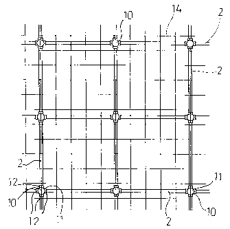
Figure 1 is a detailed top plan view of a crack inducer system
cast in a concrete slab, according to an embodiment of the invention;
Figure 2 is a cross sectional view of the crack inducer system
2 5 and slab of Figure 1;
Figure 3 is a detailed perspective view of a crack inducer system
according to an embodiment of the invention;
Figure 4 is a top plan view of a crack inducer system according
to an embodiment of the invention;
3 o Figure 5 is a cross sectional view of the crack inducer system of
Figure 4 but cast in a concrete slab;
Figure 6 is a perspective view of a connector of a crack inducer
system according to an embodiment of the invention;
CA 02417823 2003-02-03
WO 02/12630 PCT/AU01/00950
8
Figure 7 is a perspective view of a connector of a crack inducer
system according to an embodiment of the invention;
Figure 8 is a detailed top plan view of the connector of Figure 7
shown attached to some crack inducers of a crack inducer system;
s Figure 9 is a perspective view of a connector of a crack inducer
system according to an embodiment of the invention;
Figure 10 is a detailed top plan view of the connector of Figure 9
shown attached to some crack inducers of a crack inducer system; and
Figure 11 is a detailed side elevation view of the connector of
to Figure 10.
DESCRIPTION OF THE PREFERRED EMBODIMENTS
In all of the figures, like reference numerals refer fio like parts.
The figures show a crack inducer system for inducing cracks in
a large continuous concrete slab 1. The system comprises a plurality of crack
s5 inducers 2 arranged relative to a concrete-pouring surface 3 and adapted to
be cast in concrete. The inducers 2 are sized, shaped and spaced to
promote fine cracking in the vicinity of the inducers 2 throughout the area of
the slab when the concrete begins to set.
Figures 1-5 show that the crack inducers 2 are elongate. Figure
20 2 shows that the inducers 2 can be, for example, circular 4, hexagonal 5,
rectangular 6 or triangular 7 when viewed in transverse cross section. Figure
2 further shows that a crack inducer 2 can comprise several elongate
members 8 stacked or bundled together.
Figures 3-5 show a particularly preferred embodiment of the
25 invention wherein the crack inducers 2 comprise PVC pipes. Inducers 2 of
this form can be used to reticulate services, eg. electrical services.
Figure 2 and 3 show that the crack inducers 2 can be held in
place on the surface with pegs 9 or the like (if grade or subgrade), or with
nails or the like (if formwork).
3 o Figure 1 shows that the crack inducers 2 can be arranged
substantially parallel to one another. This may be desirable when
constructing a continuous narrow pavement or path. Figures 3 and 4 show
that for slabs of greater breadth (eg. driveways), the inducers 2 can be
CA 02417823 2003-02-03
WO 02/12630 PCT/AU01/00950
9
arranged as a rectangular grid. The grid comprises a first group of spaced,
substantially parallel inducers 2 and a second group of spaced, substantially
parallel inducers 2 perpendicular to the first group.
The crack inducers 2 are preferably connected to one another
with connectors. Various embodiments of connectors are shown in Figures 4-
11. The connectors generally have a body and four arms extending
therefrom. Figures 4 and 5 show a first embodiment of the connector 10,
Figure 6 shows a second embodiment of the connector 20, Figures 7 and 8
show a third embodiment of the connector 30, and Figures 9-11 show a fourth
Zo embodiment of the connector 40. Connectors 20, 30 and 40 are preferably
produced by plastic injection moulding.
Referring now to Figures 4 and 5, the connector 10 is an
electrical junction box. The box 10 has a central generally cylindrical body
11
and four arms 12 extend from the body 11. Each of the arms 12 is hollow in
construction and is attachable to an end of a crack inducer 2. The box 10 can
serve as a bar chair, wherein steel mesh 14 rests on a top surface 13 of the
box 10.
Referring now to Figure 6, the connector 20 comprises a
cylindrical body 21 with four arms 22 extending from the body 21. Each arm
22 comprises two blades 22 that intersect at a midpoint such that an end of
each arm 22 is cross-shaped when viewed in transverse cross section. Each
arm 22 can friction fit to an internal surface of an end of an inducer 2 and
can
fit to inducers of slightly varying diameter as the inducers 2 can flex
somewhat. The blades 22 are tapered at their ends 23 to further facilitate
attachment.
The connector 20 can be held to the surface below by driving a
peg, stake or the like through an aperture 24 of the cylindrical body 21.
Connector 20 is of most use with fibre-reinforced slabs where steel mesh and
bar reinforcement is not needed.
3 o Referring now to Figures 7 and 8, connector 30 is similar to
connector 20, except that it further has a ground-bearing base 31 from which
extends the cylindrical body 21. The base 31 has a plurality of apertures 32
through which nails, spikes and the like may be driven into the surface below.
CA 02417823 2003-02-03
WO 02/12630 PCT/AU01/00950
The base 31 also has a raised reinforcement lip 33 extending about a
periphery of the base 31 and the lip 33 is continuous with some of the blades
22. Such a connector 30 is of most use when constructing a fibre-reinforced
slab.
5 Referring now to Figures 9-11, the connector 40 has a body
comprising a ground-bearing base 41, four walls 42 that extend upwardly
from the base 41 and which intersect at a central location of the body, and a
retainer 43 that extends from a top of each wall 42. The retainer 43 is
adapted to engage a slab reinforcing member such as steel mesh, so that the
1 o steel mesh cannot slip off by accident.
The connector 40 also has four arms 47 each of which
comprises two blades 47 that intersect at a midpoint such that an end of each
arm 47 is cross-shaped when viewed in transverse cross section.
The base 41 has a raised reinforcement lip 45 extending about
a periphery of the base 41. The base 41 also has a plurality of apertures 46
through which nails, spikes or the like may be driven into the ground to
secure
the connector 40 to the surface below.
Each wall 42 has a vertical end wall 48 that is situated above the
iip 45. The end walls 42 taper towards the respective retainer 43. Each arm
2 0 47 extends from an end wall 48 and from the lip 45. The blades 47 have
tapered ends 49 to facilitate attachment to the inducers 2.
In use, crack inducers are arranged on grade/subgrade or on a
plastic membrane laid on grade/subgrade. The inducers may be arranged as
shown in Figure 1 for narrow slabs (eg. pathways) or as shown in Figures 3-5
2 5 for wider slabs (eg. driveways, flooring). The inducers are spaced at
800mm-
3000mm centres, preferably 800mm-1000mm centres. The ends of the
inducers are connected with connectors. The inducers and/or connectors
may be fastened to the surface below.
The connectors may double as bar chairs if steel fabric and/or
3 o bar reinforcement is to be used. If required, additional conventional bar
chairs may be used. For suspended slabs, the inducers may be cast
between top and bottom reinforcing members.
Once the inducers, connectors and reinforcing members are in
CA 02417823 2003-02-03
WO 02/12630 PCT/AU01/00950
11
place, the concrete is poured and allowed to set. If the slab is likely to be
subjected to major fluctuations in temperature, then conventional expansion
joints may be used. Cold joint pour breaks, otherwise known as construction
joints, can be used to break up the construction into manageable daily
s portions. As the concrete sets, a multitude of fine cracks propagate around
the crack inducers, as opposed to large cracks propagating at distant and
random centres.
The crack inducer system enables concrete slabs of virtually any
size to be poured directly on grade without the need for control joints. The
so system components are quick and easy to install, and result in
significantly
cheaper construction and maintenance of slabs for retail, commercial and
industrial purposes.
Conventional slabs on grade for retail, commercial and light
industrial developments would generally contain formed or sawn control joints
i5 at 5-15 m centres in both directions. If the centres are increased, then
there
would usually also be an increase in the reinforcement.
The concept with conventional slabs on grade is that the control
joints accommodate all of the shrinkage and thermal contraction strains, and
that the reinforcement mesh limits crack width within each slab panel. It
2 o follows that the greater the spacing of the control joints, the larger the
movement that has to be accommodated at each joint. The alternatives to
date have been heavily reinforced continuous pavements and post-tensioned
slabs. Both have- been used to reduce the need for control joints when the
cost increase can be justified, but neither is normally used for retail,
25 commercial and light industrial floor slabs. Special detailing is required
with
these systems, and there is much room for error during construction. Also,
problems often arise in accommodating the large movements that occur at
the extremities of such slabs.
The inventors have moved in the opposite direction with the
3 o crack inducer system. Rather than increase the spacing of control joints
and
hence the potential movement that occurs at them, the inventors have
replaced the joints with induced, regularly spaced fine cracks. Rather than
increase the reinforcement for crack control of large slab panels, the
inventors
CA 02417823 2003-02-03
WO 02/12630 PCT/AU01/00950
12
have reduced it. Rather than providing for restraint-free shrinkage of large
slab panels, the inventors have introduced restraint throughout the entire
slab
to assist crack induction at close centres.
The system revolves around the broad concept of inducing
closely-spaced, hairline cracks above the crack inducers, so that the cracks
will be of no consequence to the structural performance of the slab. The
pattern of hairline cracks does not require surface treatment, does not
adversely affect surface finishes if they are correctly applied, and is
generally
of no concern aesthetically. Further, there is minimal accumulation of stress
so in the bonding medium of any subsequently laid floor finishes, and no
control
joints to be reflected in the finishes.
Importantly, the cracks are induced from the moment the
concrete begins to set. This, combined with the uniform spacing of the crack
inducers and the uniformity of the slab and its reinforcement, provides the
best possible opportunity for cracks to occur only where they are intended.
With conventional sawn joints, for example, the initial wandering crack has
often occurred before the saw cut is installed.
Also in contrast to conventional systems, where it is normal to
implement measures to minimise restraint from the subgrade (eg. sand
2 o blinding layers), with the present system, special measures may be taken
to
increase subgrade friction and general shrinkage restraint, as they both help
to ensure the cracks are induced at the regular centres.
The connectors can double as the reinforcement support. The
reinforcing steel mesh is simply placed onto the connectors and the need for
traditional bar chairs is generally eliminated. The connectors provide an
extremely stable support for the reinforcing mesh, and in return the weight of
the mesh is sufficient to hold the connectors and crack inducers in place
during concrete placement.
A specific example of slab construction will now be described.
3 o The crack inducer system has been used to construct a 4,042 square metre
floor area for a supermarket, without control joints. The slab was 125mm thick
throughout and was reinforced with F62 mesh placed with about 30mm top
cover. A grid of crack inducers was used to induce closely spaced fine cracks
CA 02417823 2003-02-03
WO 02/12630 PCT/AU01/00950
13
throughout the area of the slab. The crack inducer grid comprised 33mm
diameter PVC pipes at 1 m centres in both directions, the diameter of the
pipes being approximately 25% of the thickness of the slab. Four-way
connectors were used to connect the crack inducers and to provide a surface
at 70mm above the concrete-pouring surface to support the reinforcing mesh.
The slab extended throughout the entire area of the supermarket, including
the trading area, the cool rooms, the food preparation areas, and the reserves
area.
Some of the advantages of the system for constructing slabs on
so grade can be summarised as follows:
All formed and sawn control joints, together with sealants,
are eliminated
Reinforcement requirements may be reduced
Skilled labour is not required to install the crack
15 inducer/connector grid
There are no formed or sawn control joints to have their
edges broken or damaged during construction or during service
The closely spaced pattern of fine cracks maximises the
ability of a slab to accommodate minor ground movements without distress
2 0 . There is minimal and generally no risk of slab panels curling
at the corners
Large continuous areas of slab can be placed in a single
concrete pour, the limitation generally being only the capacity of the
contractor to place and finish the concrete
2 5 . Construction joints at pour breaks can be installed at short
notice with minimum effort
There are no control joints to be reflected in the applied
finishes
Conventional machinery can be used
3 o There are significant reductions in construction time . and cost
produced by each of the above.
Whilst the above has been given by way of illustrative example
of the invention, many modifications and variations may be made thereto by
CA 02417823 2003-02-03
WO 02/12630 PCT/AU01/00950
14
persons skilled in the art without departing from the broad scope and ambit of
the invention as herein set forth.