Note : Les descriptions sont présentées dans la langue officielle dans laquelle elles ont été soumises.
CA 02418495 2003-02-06
WO 02/13925 PCT/CA01/01139
INDEPENDENT WHEEL SUSPENSION SYSTEM
FIELD OF THE INVENTION
The present invention relates to a wheel suspension system and
more particularly to a wheel suspension system that provides independent wheel
suspension and optimal shock absorption with a user accessible tension
adjustment device.
BACKGROUND OF THE INVENTION
The field of wheel suspension system taken, for example, within the
context of its application to in-line roller skates has experienced a great
deal of
interest over the past few decades. As the standard four (or five) wheel
roller
skate, which was used primarily for recreational means in indoor arenas, was
adapted to outdoor use for both recreation and as a means of transportation,
new
design features needed to be adopted to the wheel suspension system. The new
application of the wheel suspension system needed to be strong and stable
enough to handle the weight and balance of people of varying height and weight
as well as.able to easily absorb the shocks caused by uneven and rough terrain
and small objects or bumps always present on the road or tracks.
. In the hopes of improving the quality of the ride, various new
suspension systems were designed to improve the shock absorption of in-line
roller skates.
U.S. Pat No. 5,816,588 issued to Nicoletti on October 6, 1998
discloses a carrier for an in-line roller skate with a removable suspension
means
to provide variation in the distance between the wheels to increase shock
absorption and increase maneuverability.
1
CA 02418495 2003-02-06
WO 02/13925 PCT/CA01/01139
U.S. Pat No. 5,823,543 issued to Burns et al on October 20, 1998
discloses a suspension system for an in-line boot with a double pivot
mechanism
attached to a boot while U.S. Pat No. 5,951,027 issued to Oyen et al on
September 14, 1999 discloses a shock absorption system with a double piston
wheel suspension mechanism.
U.S. Pat No. 5,704,621 issued to Lazarevitch et al on January 6,
1998 discloses a suspension system with C-shaped springs secured to side rails
positioned on either side of the wheels which might not be efficient if the
wheel
hits an obstacle with a lateral angle or if the two springs are not exactly
identical
to each other.
The limitations of the prior art is that the tension of the shock
absorption member of previously available models, if any, ,has to be
professionally adjusted by the manufacturer/retailer. We know that the tension
of
roller blade wheels has to be altered depending on the degree of expertise of
the
user of when the latter whishes to increase, his speed while gliding in a
circular
motion as opposed to when he wishes to skate in a straight line. In an attempt
to
solve this problem some systems are provided with different wheel or tension
components for different tension levels. This was both inconvenient for the
product user as well incurred an added expense in production. None of the
known products provides the ability for the user to easily and quickly adjust
the
tension of the shock absorption unit of each individual wheel.
A further limitation of known suspension systems is that none of
then provides an independent suspension system with a wheel mechanism that
allows for as great a displacement when an upward force is applied to the
wheel,
along with a shock absorbent device following the displacement of the wheel.
2
CA 02418495 2003-02-06
WO 02/13925 PCT/CA01/01139
OBJECTS OF THE INVENTION
It is therefore a general object of the present invention to provide
improved independent suspension system for mounting a wheel than what is
currently available on the market.
It is another object of the present invention to provide an
independent suspension system for mounting a wheel that allows for immediate
and simple tension adjustment by the user.
It is still an object of the present invention to provide an
independent suspension system for mounting a wheel that has a large angle
range of rotation and thus provides an increased shock absorption and a
smoother ride.
It is yet an object of the present invention to provide an independent
suspension system for mounting a wheel that has a shock absorbent device
following the displacement of the wheel to ensure an optimum absorption.
, It is a further object of the present invention to provide an
independent suspension system for mounting a wheel whose system includes a
specially designed truck frame with curvilinear cutouts adapted . to receive
rearwardly pivoted respective wheel unit.
It is yet a further object of this invention to provide a simple
inexpensive system to manufacture and upkeep.
The present invention pertains to an independent suspension
system for mounting a wheel to be used for any device mounted on rollers or
wheels such as, but not limited to, in-line roller skates and the like
recreational
equipment designed for rough terrain maneuverability.
3
CA 02418495 2003-02-06
WO 02/13925 PCT/CA01/01139
Other objects and advantages of the present invention will become
apparent from a careful reading of the detailed description provided herein,
within
appropriate reference to the accompanying drawings.
SUMMARY OF THE INVENTION
The present invention provides a wheel suspension system
comprising:
- a truck for mounting on a movable structure;
- a swing arm pivotally connected to said truck for rotation around a
horizontal axis between first and second limit positions;
' - at least one wheel rotatable on said swing arm;
- a shock absorbent device including a shock absorber and a guide, said
guide having a first end pivotally connected to said truck, said shock
absorber
mounted coaxially on said guide and having opposite ends abutting said swing
arm and a free second end of said guide, respectively, whereby said shock
absorbent device can freely follow rotation of said swing arm between said
limit
positions; and
- a user accessible tension adjuster for adjusting the tension of said shock
absorber.
Preferably, the shock absorber is a coil spring, or a gas piston
mechanism.
Preferably, the swing arm includes a rear, lower section rotatably
supporting said wheel and a front, upper section pivotally connected to said
truck.
Preferably, the upper section of the swing arm includes a horizontal
and forwardly extending first plate, and a downwardly and rearwardly extending
4
CA 02418495 2003-02-06
WO 02/13925 PCT/CA01/01139
second plate abutting the truck in said first and second limit positions,
respectively.
Preferably, the system includes a layer of elastomer on said first
and second plates for smooth contact with said truck.
Preferably, the truck has an inverted U-shaped cross-section bar to
rotatably support the wheel and protect the shock absorbent.device.
Preferably, the system includes a brake unit releasably secured to
the truck rearwardly of the swing arm, the wheel abutting and rubbing against
the
brake unit immediately before the swing arm reaches the second limit position
upon application of an external force by a user.
Preferably, the guide is a screw-nut assembly also defining the
tension adjuster of the shock absorber.
Preferably, the shock absorbent device is located in front of said
horizontal axis.
Preferably, the rotation of said swing arm between the first and
second limit positions corresponds to a swing angle between fifteen and forty
degrees.
Alternatively, the present invention provides a combination of a
plurality of wheel suspension systems, wherein the swing arms are coplanar and
positioned in-line from front to back of said movable structure, thereby
providing a
plurality of in-line wheel suspension systems.
Preferably, the swing arms are pivotally secured to a common
elongated truck.
Preferably, the combination includes a brake unit releasably
secured to' the truck rearwardly of a rearmost swing arm, the wheel of the
5
CA 02418495 2003-02-06
WO 02/13925 PCT/CA01/01139
rearmost swing arm abutting and rubbing against the brake unit immediately
before the rearmost swing arm reaches its second limit position upon
application
of an external force by a user.
BRIEF DESCRIPTION OF THE DRAWINGS
In the annexed drawings, like reference characters indicate like
elements throughout.
Figure 1 is a perspective side view of a plurality of a same
embodiment of an independent wheel suspension system according to the
present invention;
Figure 2 is a partially sectioned side view of the embodiment of
Fig. 1;
Figure 3 is an enlarged partially sectioned side view of the
embodiment of Fig. 1, showing the two pivotal limit positions of the wheel
support
unit;
Figure 4 is a section view taken along line 4-4 of Fig. 3;
Figure 5 is a partially sectioned view taken along line 5-5 of Fig. 3;
Figure 6 is a view similar to Fig. 4 showing a second embodiment of
the shock absorbent of a wheel suspension system according to the present
invention;
Figure 7 is a view similar to Fig. 5 showing the embodiment of
Fig. 6; and
Figure 8 is a section view taken along line 8-8 of Fig. 6.
6
CA 02418495 2003-02-06
WO 02/13925 PCT/CA01/01139
DETAILED DESCRIPTION OF THE PREFERRED EMBODIMENTS
With reference to the annexed drawings the preferred embodiments
of the present invention will herein be described for indicative purposes and
by no
means as of limitation.
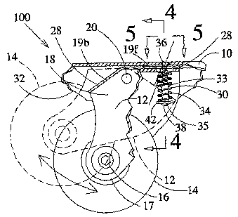
Fig. 1 shows a perspective side view of a plurality of a same
embodiment 100 of an independent suspension system according to the present
invention, for preferably mounting one wheel 14 (or roller). The suspension
system 100 includes supporting frame, preferably made up of an outer truck
structure 10, a swing arm wheel support unit 12 pivofially secured thereto for
rotation around a horizontal axis H (see Fig. 4), and a .shock absorbent
device
member 30, preferably a shock absorber coil spring 34, having a user
accessible
tension adjuster, preferably a screw-nut assembly 35, for adjusting the
tension of
coil spring 34 and a guide 33 for guiding its displacement. The spring 34 and
its
guide 33 are mounted in between the truck structure 10 and the swing arm wheel
support unit 12.
Preferably, a plurality of independent wheel suspension systems
100 are all pivotally secured to a same truck structure 10 attached to the
underside, usually rigid, of a roiling device or movable structure, for
example an
in-line roller-skate boot B (as shown by the dashed lines .in Fig. 1 ), the
suspension systems 100 being positioned in-line from front to back. As seen.
in
Figs. 1 and 2, the wheels 14 and their respective suspension system 100
function
independently of each other.
The swing arm wheel support unit 12 preferably includes a rear
lower section 17 rotatably supporting the wheel 14 via a shaft 16 and a front
upper section 18 adapted to be pivotally mounted to the truck structure 10 via
a
7
CA 02418495 2003-02-06
WO 02/13925 PCT/CA01/01139
pin 20 with axis H, for rotation between a first and a second limit positions.
Accordingly, the truck structure 10 is preferably made out of an inverted
U-shaped cross-section bar to support and protect the shock absorbent
member 30.
The upper section 18 of the wheel support unit 12 preferably
includes a substantially horizontal and forwardly extending first plate 19f
and a
downwardly, with an angle preferably varying between fifteen (15) and forty
(40)
degrees, and rearwardly extending second plate 19b. First and second plates
19f, 19b being adapted to abut the truck structure 10 in the first and second
swing arm wheel support unit limit positions respectively, shown in solid and
dashed lines in Fig. 3 respectively.
At rest, with no weight supported by the suspension system 100,
the latter is biased in its first limit position as shown in solid lines in
Fig. 3, by the
spring 34 of the shock absorbent member 30. During normal rolling of the
wheels
14 supported by their respective suspension system 100, the latter is adapted
to
have its shock absorbent member 30 setting the wheel support unit 12 at
essentially mid position between the two limit positions, as depicted in Fig.
2 for
the frontmost and the two rearmost suspension systems.
When hitting an obstacle O or bump on the road surface S or
uneven and rough terrain/road tracks, the wheel 14 pushes its swing arm
support
unit 12 up toward its second limit position, depending on the size of the
obstacle
O, as shown for the second frontmost suspension system of Fig. 2, and by
dashed lines in Fig. 3
Obviously, more than one coaxial wheel 14 could be mounted on a
same shaft 16, if required. .
8
CA 02418495 2003-02-06
WO 02/13925 PCT/CA01/01139
Also, the truck structure 10 preferably includes a curvilinear cutout
32 rearwardly positioned from the swing arm support unit 12 and adapted to
receive the wheel 14 when the support unit 12 is nearby the second limit
position,
in order to avoid physical contact between the wheel 14 and the structure 10.
The suspension system 100 further includes a brake unit 22
releasably secured to the truck structure 10 rearwardly of the swing arm
support
unit 12, such as for the rearmost suspension system of Fig. 2. The brake unit
22
includes a preferably rubber type material pad 24 for the wheel 14 to abut and
rub there against immediately before the support unit 12 reaches its second
limit
position, upon application of an external force by the user. Depending on the
.
external force, the wheel 14 is either decelerated or completely stopped from
rotating. The brake pad 24 is releasably secured by a screw-nut arrangement 26
for easy interchangeability after complete wear.
In order to prevent hard shocks when the first and second plates
19f, 19b of the wheel support unit 12 abuts the truck structure 10, they are
preferably covered by a layer of elastomer or rubber type material 28, thus
smoothing off the impacts.
As shown in Fig. 4, the screw-nut assembly 35, preferably coaxial
to the spring 34, is used to regulate the tension of the spring 34. The latter
is
secured between the structure 10 via the guide 33 also being the screw-nut
assembly 35 and the upper section 18 of the support unit 12. The screw-nut
assembly 35 consists of the guide 33 for the spring 34 with a top end part 36
pivotally secured to the truck structure 10 in order to enable a free bottom
end
part 38 to freely follow the rotation of the support unit 12. This rotational
displacement of the top part 36 is enabled by the truncated shape of its head
9
CA 02418495 2003-02-06
WO 02/13925 PCT/CA01/01139
positioned into a countersink type hole 40 in the truck structure 10, and the
slot
hole 41 provided into the first plate 19f of the top section 18 of the support
unit
12, as illustrated in Fig. 5. The adjustment of the tension of the spring 34
is
simply made by the user tightening the bottom part 38 into the top part 36
using a
tool such as a standard screwdriver to compress the two ends of the spring 34
abutting the bottom part of the guide and the first plate 19f of the swing arm
12
respectively. Preferably, an elongated washer 42 prevents the screw-nut
assembly 35 from lateral swinging. The adjustment of the tension is preferably
limited by the limited tightening of the bottom part 38 to the top part 36.
1.0 Alternatively, optional ears 43 upwardly projecting from the washer 42,
shown in
dashed lines in Fig. 4, could also be used to limit the adjustment of the
tension of
the spring 34.
With an external and substantially vertical force applied to the wheel
14 while hitting a rock, a bump or the like, the entire swing arm support unit
12 is
forced to pivot clockwise, when referring to Fig. 3, and compress the spring
34 of
the shock absorbent member 30 between the first plate 19f and the bottom part
38 of the screw-nut assembly 35, itself retained by the truck structure 10.
When
the external force is removed, the spring 34 restores the support unit 12 into
its
previous position.
Alternatively, the shock absorbent member could also be either a
piece of any resilient material such as rubber type materials (not shown), or
a
preferably gas piston mechanism 44 secured between the truck structure 10 and
the swing arm support unit 12, as shown in Fig. 6. Similarly to the top part
36 of
the screw-nut assembly 35 used with the spring 34, the top part of the piston
mechanism 44 of this second embodiment 100a, preferably the cylinder 46,
CA 02418495 2003-02-06
WO 02/13925 PCT/CA01/01139
pivots around its attachment point to the structure 10. The slot hole 41 a,
shown
with an opened end on Fig. 7, of the first plate 19f is obviously sized to
allow for
the cylinder 46 to freely go through. The bottom end of the piston mechanism
44,
namely the piston 48 is preferably pivotally secured to a transversal pin 54
mounted onto the swing arm support unit 12.
Preferably, the piston mechanism 44 also includes a screw-nut
assembly 35a with a top part formed by a threaded blind hole into the pistori
48
adapted to be engaged by the bottom part, a screw 50 attached to the pin 52,
as
shown in Figs. 7 and 8.
. For weight cost and anti-corrosion purposes, the truck structure 10
and the swing arm support unit 12 are preferably made out of aluminum.
Obviously, depending on the usage and other requirements related to the
adjustable independent suspension system 100 of the present invention, other
types of materials or alloys could be used.
Although the present independent wheel suspension system has
been described with a certain degree of particularity and details, it is to be
understood that the disclosure has been made by way of example only and that
the present invention is not limited to the features of the embodiments
described
and illustrated herein, but includes all variations and modifications within
the
scope and spirit of the invention hereinafter claimed.
11