Note : Les descriptions sont présentées dans la langue officielle dans laquelle elles ont été soumises.
CA 02418888 2003-02-14
A METHOD AND APPARATUS TO IMPROVE CHIRPED FIBER BRAGG
GRATING GAIN FLATTENING FILTERS
FIELD OF THE INVENTION
s The present invention generally relates to a method and an apparatus for
improving the fabrication of complex fiber Bragg grating (FBG) filters. More
particularly, The invention concerns a method and apparatus for quickly
modifying
the spectral response curve of FBG filters in order to precisely match a pre-
defined
target spectra, preferably but not exclusively the inverse gain profile of an
Er
io doped fiber amplifier (EDFA).
BACKGROUND OF THE INVENTION
FBGs and chirped FBGs are widely used technologies to fabricate complex
filters. Gain flattening filters for EDFAs are but one example. Gain flatness
of
is optical amplifiers over the communication bandwidth is a key requirement of
high
performance optical Wavelength Division Multiplexing (V11DM) communication
systems. Usually, a gain flattening filter with a spectral response matching
the
inverse gain profile is incorporated within the amplifier to flatten its gain.
Several gain flattening filter technologies can be used to perform the gain
2o equalization, thin film filters and chirped FBGs being the most widely used
(1). A
key metric of performance for gain flattening filters is the insertion toss
error
function (ILEF): the difference between the measured attenuation of the fitter
and
the target spectra. The target spectra is specific to each amplifier design
and is
closely related to the inverse gain curve. Because amplifiers are often
cascaded
Zs along a link, the cumulative effect of the error function of the individual
filters is
also of importance. Individual filter ILEF smaller than or equal to ~0.1 dB
for the
full operating temperature and wavelength range of a system are often
required,
and the ILEF must be as random as possible to avoid the additive effect of
systematic errors. In the case of thin film filters-gain flattening filter,
the
~o manufacturing process is such that all gain flattening filters have very
similar error
CA 02418888 2003-02-14
2
functions of the order of ~0.25 dB and these systematic errors can add up to
unacceptable levels.
The chirped fiber Bragg grating is an attractive technology to produce very
low error gain flattening filters. Aithough several manufacturing approaches
are
s possible, gain flattening filters are typically inscribed in photosensitive
fibers using
UV light and a chirped phase mask to create an interfering pattern with
linearly
changing period along the grating. The amplitude of the resulting index
modulation
can also be shaped by controlling the intensity of the UV-light along the
phase-
mask. This shaping and trimming process at the UV-writing station is required
to
~o obtain low 1LEF.
UV-induced defects are responsible for the grating formation but these
defect sites are not thermodynamically stable and the change in refractive
index
can be reversed. This is why gratings are then subjected to a stabilization
process,
which is a controlled temperature anneal. This annealing progressively removes
Is the most unstable defect sites and the final grating is stable within the
system
tolerances for the intended grating lifetime. Of course, the annealing step
reduces
the refractive index modulation and consequently, the grating must be written
stronger in order to hit the post-annealing target. This manufacturing process
is
quite adequate for ILEF of the order of ~0.25 dB. However, imperfections in
the
2o phase mask, mechanical and laser instabilities make if very difficult to
obtain ILEF
smaller than ~0.15 dB. In those cases, a lengthy manual UV-trimming process is
often required. Even then, the subsequent temperature annealing process can
slightly distort the final spectral shape and the resulting production yield
is low.
Finally, because the UV-trimming process is operator dependent, it often leads
to
2s small but noticeable systematic errors in the ILEF. Very similar process
steps
apply to other types of complex filters based on FBGs and chirped FBGs. In
those
cases, the metric can be something other than the ILEF but the general method
and apparatus described in this invention would apply equally.
~o
CA 02418888 2003-02-14
J
OBJECTS AND SUMMARY OF THE INVENTION
It is therefore an object of the present invention to provide a method and
apparatus allowing a more precise tailoring of the characteristic spectra of a
complex FBG filter than for prior art manufacturing techniques.
s It is a preferable object of the invention to manufacture gain flattening
filters
having an ILEF smaller than ~-g.15 dB.
In accordance with an aspect of the present invention, the trimming and
annealing steps are combined into a single process in order to efficiently
fabricate
complex FBG filters with improved performance. In the case of gain flattening
~o filters, this lead to filters with very low ILEF. More particularly, the
present
invention automatically generates a controlled temperature profile along the
FBG
in order to precisely control the annealing process until the FBG spectral
curve
equals the target curve.
Advantageously, the present invention makes possible the creation of any
is desired temperature profile along the length of the FBG. It allows to
precisely
locate the FBG in space, and to affect local correction to the FBG spectral
curve
without affecting nearby points. The method and apparatus of the present
invention also make it possible to estimate the necessary time and temperature
to
affect the required correction and end-of-life performance of the FBG after
final
2o processing, and estimate and take into account cladding mode losses of the
FBG.
Systematic errors between the final spectral curve and the target curve on a
cascaded series of FBGs are advantageously reduced.
Other features and advantages of the present invention will be better
understood upon reading of preferred embodiments thereof with reference to
fihe
2s appended drawings.
BRIEF DESCRIPTION OF THE DRAWINGS
FIG. 1 is a graph (left) representing isochronal annealing curves for a
typical
CFBG-GFF. At any given wavelength, the behavior is well represented by a
~o master curve (right).
CA 02418888 2003-02-14
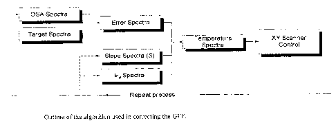
FIG. 2 is a flow chart of the algorithm used in correcting the gain flattening
filter.
FIG. 3 is a schematic of the annealing-trimming station.
FIG, 4 (top) shows the applied laser fluence (temperature) profile. Bottom
s curves are the measured and predicted changes in the GFF transmission
spectra.
FiG. 5 shows the evolution of the error function from start (bottom trace) to
finish (top trace). Each trace represent a 10 seconds profiled annealing.
DESCRIPTION OF PREFERRED EMBODIMENTS OF THE INVENTION
to The present invention concerns a method and apparatus where the
requirements at the UV-writing station are considerably relaxed when compared
to
prior art techniques. No UV-trimming is necessary and it is sufficient, in the
case of
gain flattening filters, that the FBG attenuation curve be everywhere superior
to the
target attenuation curve, with provision for the annealing step. Then, instead
of a
is uniform annealing, the next step involves a controlled annealing along the
grating
length in order to precisely match the target spectra. This requires both a
good
understanding of the ageing/annealing process along the FBG and a mean to
precisely control it.
The ageing curve or master curve approach to decay analysis has proven
2o to be a useful model to understand and predict the change in refractive
index
modulation (fin) versus time and temperature (3). In this model; the change in
refractive index modulation is a function of the ageing parameter, or
equivalently
the demarcation energy Ed:
final initial
2s ( On )t;oai ' ( ~ )initial 'i' s ( Ed - Ed ) (1)
where s is the slope parameter related to the defects energy distribution and
E~ is
a function of temperature (T) and time (t):
fl Ea = ki3oltzman'T Iri( va t) (2)
CA 02418888 2003-02-14
where vo is the frequency factor, a constant for a given fiber type and UV-
writing
process. This model was extended to the case where the slope factor s can
change along the grating, or equivalently, as a function of the wavelength in
the
filter spectra (s(A)) of a chirped FBG. The validity of this assumption is
supported
s by its success in predicting the change in refractive index modulation with
temperature and time
FIG. 1 illustrates how it is applied to a specific gain flattening filter. The
gain
flattening filter was submitted to a series of isochronal annealing steps of
increasing temperature. The master curve for a specific wavelength (vertical
line
io on the left-hand graph) is also shown on the right-hand graph. The results
fit very
well with equation 1. In practice, the calculated slope can vary along the
length of
the grating. Once s(h) is known, it is possible to calculate the required
annealing
conditions that will reduce the refractive index modulation by a given amount.
In
this fashion, the transmission spectra can be matched to any lower-toss
target.
Is Trimming the gain flattening filter spectral curve in this fashion requires
a
well controlled heat source. The C02 laser is a particularly well adapted heat
source for silica glass in general and optical fibers in particular. The
coefficient of
absorption of 10 ~m radiation is so high for silica that most of the power is
absorbed within the first 10-2d ~,m thick layer. Also, silica can tolerate
very rapid
2o heating and cooling cycles because its coefficient of thermal expansion (.)
is so
low. Fiber optic splicing or cleaving and the fabrication of long period
gratings are
just a few examples of the many uses of C02 lasers in this field (4,5). The
lasers
themselves are cheap, robust and require very little maintenance.
Assuming then that the temperature profile along the grating can be
as controlled, FIG. 2 outlines the general annealing-trimming process. The
s(~) and
Ed spectra are added to the error spectra to calculate the required
temperature
profile, assuming a fix length heating cycle. The process is repeated until
the
required tolerances on the error function is reached. F(G. 2 does not show the
initial calibration phase where two rapid uniform temperature anneals are
o performed from which initial values for s(A) and E~ are calculated.
CA 02418888 2003-02-14
6
FIG. 3 is a schematic of the annealing-trimming station. Afl components and
measurements are computer controlled. An important hardware component for this
particular system is the XY-scanner which allows fast and precise positioning
of
the laser beam along the chirped FBG. During the annealing-trimming steps, the
s laser beam is constantly scanned at high speed along the chirped FBG. The
required precise temperature profile is obtained through a position-modulated
technique which essentially controls the laser fluence along the grating by
locally
varying the scan speed. Alternately, the scan speed could be fixed and the
laser
fluence could be modified as a function of its position along the grating.
Another
to possibility is to have the scan speed and laser fluence fixed and to add a
rapid
oscillating movement of the laser beam in the axis perpendicular to the fiber
axis.
Ajusting the amplitude of this perpendicular oscillation as the beam moves
along
the fiber would also have the same effect as varying the local laser ffuence.
Each new gain flattening filter to be processed is roughly positioned in place
is by the operator and connected to the optical spectrum analyzer {OSA). A low-
temperature heat-scan technique is then used to automatically calibrate the
position of the grating. A similar technique can be used to estimate the
grating
strength and thus cladding mode losses along the chirped FBG.
in short, the software does all data processing and commands a
2o temperature profile, and the hardware provides the mean to create the
temperature profile along the chirped FBG. Of course, in practice, in order to
achieve repeatable and precise trimming, the algorithm must take into account
many other factors such as: cladding mode losses, frequency response of the
scanner, finite laser beam width and fiber thermal response. Nevertheless,
2s because of the multi-step approach and the self-adapting algorithm, the
process is
very robust.
FIG. 4 illustrates a specific example of the results obtainable with the
present invention. fn this case, a chirped FBG gain flattening filter was
submitted
to an arbitrary temperature profile to simulate corrections in 4 distinct
zones.
~o Learning from previous annealing steps, the software was able to accurately
predict the resulting change in the gain flattening filter spectra; even
smaller
CA 02418888 2003-02-14
7
details like the tail of rightmost zone and the overlap of the two middle
zones were
correctly calculated.
The following example illustrates the overall process, FIG. 5 shows the
evolution of the error function from the moment the gain flattening fitter
arrived at
s the station and for several of the 10 seconds trimming scans. In this
particular
case, the initial error is unusually large because the gain flattening filter
was
intentionally overwritten to illustrate the capability of the process.
Theoretically, the
trimming could be accomplished in a single step. However, because over-
trimming
is difficult to correct, a rnulti-step approach is preferred.
io FIG. 6 illustrates the final results, showing the initial gain flattening
filter, the
target and final curve. The top graph of FiG. 6 shows the residual error
function
along with the high-frequency component of the gain flattening filter spectra
just
after UV-writing. The final error function is approximately ~0.1 dB, almost
totally .
limited by the original high-frequency component. In this case, the target
error
is function was ~Q.15 dB.
fn some special cases, reaching the required target in a specific region
along the chirped FBG could lead to over-correction to nearby regions because
of
heat diffusion. These regions can be automatically detected by the software
and
corrected by using a very fast on-off scanning process that limits heat
diffusion.
2o Some additional features are relatively easy to implement. For example, the
station can be instructed to not only consider the error function of the gain
flattening filter being process but all other previous error functions of the
same
series. This type of batch processing can further reduce the overall
systematic
error of cascaded gain flattening filters. It can also be envisioned that a
single
2s profile at the UV-writing station could fit many end-profiles, simplifying
the
manufacturing process.
The preferred embodiment described here pertains more specifically to
chirped FBG gain flattening filters but the main technique and apparatus could
also be applied to other complex FBG filters.
so Numerous modifications could be made to the embodiments above without
departing from the intended scope of the present invention.
CA 02418888 2003-02-14
8
REFERENCES
1. M. Rochette, M. Guy, S. Larochelle, J. Lauzon, F. Trepanier, "Gain
equalization
s of EDFAs with Bragg gratings", Phot. Tech. Lett. 11, 536-538 (1999).
2. F. Trepanier, M. Morin, G. Robidoux, M. Guy, "Fiber Bragg grating gain
flattening filters for high-performance optical amplifiers", Proceedings
Optical
Amplifiers and Applications conference; OME12, 14-17 July, Vancouver,
io Canada (2002).
3. S. Kannan, J. Z. Y. Guo, P. J. Lernaire, "Thermal stability analysis of UV-
induced fiber Bragg gratings", J. Light. Tech., 15, 1478-1483 (1997).
Is 4. K. Egashira, M. Kobayashi, "Analysis of thermal conditions in CO2 laser
splicing of optical fibers", Appl. Opt., 16, 2743-2746 (1977).
5. L. Drozin, P.-Y. Fonjailaz; L. Stensland, "Long-period fibre gratings
written by
C02 exposure of H2-loaded, standard fibres", Elect. Lett., 36, 742-744 (2000).
6. Y.M. Xiao and Michael Bass, "Thermal stress limitations to laser fire
polishing
of glasses", Appl. Opt., 22, 2933-2936 (1983).