Note : Les descriptions sont présentées dans la langue officielle dans laquelle elles ont été soumises.
CA 02419525 2003-02-19
-1-
RADIALLY EXPANSIBLE TIRE ASSEMBLY DRUM
AND METHOD FOR FORMING TIRES
Field of the Invention
[001] This invention relates to an improved radially expansible tire assembly
drum (10)
and a method for forming tires {2) from an assemblage of tire components
utilizing the
assembly drum (10).
Background of the invention
[002] Historically, the pneumatic tire has been fabricated as laminated
structure of
generally toroidal shape having beads, a tread, a belt reinforcement and
carcass. The tire
is made of rubber, fabric, and steel. The manufacturing technologies employed
for the
most part involve assembling the many tire components from flat strips or
sheets of
material. Each component is placed on a building drum and cut to length such
that the
ends of a component meet, or overlap, creating a splice.
[003] In the first stage of assembly, the carcass would include one or more
plies, and a
pair of sidewalk, a pair of apexes, an inner liner (for a tubeless tire), a
pair of chafers and
perhaps a pair of gum shoulder strips. Annular bead cores can be added during
the first
stage of tire building, and the ply or plies can be turned around the bead
cores to form the
"ply turnups."
[004] Typically, the carcass components (excluding the bead cores) would be
either
"butt spliced" or "lap spliced." A butt splice has the component ends joined,
but not
overlapped. A Iap splice has overlapping ends.
[005] This imermediate article of manufacture can be cylindrically formed at
this point
in the first stage of assembly. The cylindrical carcass is expanded into a
toroidal shape
after completion of the first-stage of tire building. Reinforcing belts and
the tread are
added to the intermediate article during a second stage of tire manufacture,
which can
occur using the same building drum or work station or at a separate shaping
station.
[006] During the expansion of the carcass, tensile stresses are imposed on the
spliced
and uncured components of the tire carcass.
[007] In the case of automobile or light truck tires, lap splices were
preferred because
the splice remained intact, whereas butt splices would tend to open or fail.
Even with the
good adhesion of the lap splice, the cords adjacent the splice tend~l to be
stretched
CA 02419525 2003-02-19
-z-
compensating for the overlapped two layers of cords at the splice. This
localized
stretching creates a non-uniformity that is readily visible under x-ray,
ultrasonic display
or by physically cutting the tire and visually inspecting it.
[008] The tire designer, in order to prevent the creation of tire uniformity
problems, has
historically insured that the splices of various layers of components were not
circumferentially aligned. This non-alignment of splice joints was believed to
improve
the carcass overall durability and uniformity, as measured by the amount of
force
variation and the balance of the tire. Tire engineers also have believed that
tire
uniformity could be improved if these discontinuities were deliberately
circumferentially
spaced around the carcass. This meant that each component had to be applied to
the ply
at the tire building station where each component was cut and spliced in a
spaced order.
[009] When the cord reinforced plies are placed on the building drum, it is
very
important that the geometric spacing of the beads and the ply turnups are
controlled
uniformly. Variations in the overall tire building process can result in
variations in cord
tension. These non uniformities can affect the ride and handling
characteristics of the
tire.
[0010] In U.S. Patent 6,250,356 to Nfichelin, a tire assembly drum is
disclosed wherein
the beads are two distinct sizes. Conventionally, tires are symmetrical having
equal bead
diameters. The two distinct diameters on a tire exacerbate the problems of
tire building
and the disclosed assembly drum provides a method and apparatus to permit the
tire to be
built in a more uniform and faster way. This building drum was designed to
build tires
having a given set of two different diameters at the first stage of assembly.
A separate
tire-shaping drum was used to toroidally shape the tire carcass to assemble
the tread and
belt reinforcements and that drum is disclosed in U.S: Patent 6,234;227.
[0011] The present invention has the objective of providing a building drum
that is
radially expansible and capable of building tires of equal bead diameters or
of different
bead diameters over a range of diameter sizes. In one embodiment, the building
drum
further has the objective of having axially movable ends, which can be air
tightly sealed
to permit the assembled carcass to be inflated and shaped toroidally, avoiding
removal
from the assembly drum for a second stage of tire building.
CA 02419525 2003-02-19
-3-
Summary of the Invention
[0012] An improved radially expansible assembly drum for the manufacture of
tires is
disclosed. The assembly drum has a body mounted on a drum core assembly and
presenting a receiving surface for tire components to be assembled. The ends
and the
receiving surface have the same or different diameters. A means for covering
the ends of
the receiving surface and a means for radially expanding the drum are also
provided.
The means for radially expanding the drum includes the ability to radially
expand the
receiving surface at the center and the ends of the assembly drum.
[0013] The radially expansible assembly drum has the means for radially
expanding the
assembly drum, including a cam disk having an increasing spiral cam follower
groove.
The cam follower groove provides a continuous range of selectable diameters
and stable
expansion of the drum diameters as a function of cam disk rotation. The spiral
cam
follower groove radially increases or decreases, dependent on the direction of
rotation,
causing an increase or a decrease in diametrical expansion or contraction at a
rate of 40
mm per 360° of rotation of the assembly drum. The continuous range of
selectable
diameters increases from a diameter of d; to a fully expanded diameter de, de
being equal
to or greater than d; + 50 mm.
[0014] In one embodiment of the invention, the radially expandable assembly
drum has a
means for axially moving the ends of the assembly drum, the ends being
simultaneously
movable from an axially widely spaced location to an axially inner location
closer to a
centerline of the assembly drum. This movement of the two ends is preferably
equal in
axial displacement. This reduction in axial space between the two ends permits
the cords
of the ply to be radially expanded and the assembled tire carcass to be
toroidally shaped
to permit the tread and reinforcing belt structure to be assembled while the
assembled
tire is held on the radially expansible assembly drum.
[0015] The mufti-movement capability of the assembly drum is achieved by this
unique
drum core assembly. The drum core assembly includes a spindle for rotating the
assembly drum, a driving shaft which passes through the center of the spindle,
and a first
external shaft connected to the means for ra.dially expanding the assembly
drum. The
first external shaft is parallel and eccentrically located relative to the
centerline of the
spindle. The driving shaft provides rotary motion to the first external shaft,
via a first
external clutch mechanism. The engagement of the first clutch mechanism
rotates the
first external shaft to initiate radial expansion or contraction ofthe dmm
aaePmhtv
CA 02419525 2003-02-19
-4-
[0016] The drum core assembly further includes a second external shaft
connected to the
means for axially moving the ends of the assembly drum. The second external
shaft is
parallel to and eccentrically located relative to the centerline of the
spindle. The second
external shaft is connected to a second clutch mechanism. The engagemem of the
second clutch mechanism (to the driving shaft) rotates the second external
shaft to
initiate axial movement of the ends of the assembly drum.
[0017] The second external shaft has oppositely directed threads, one set of
threads
being connected to one end of the assembly drum, the oppositely directed
threads being
connected to the opposite end of the assembly drum. Rotation of the second
external
shaft in one rotating direction moves the ends of the assembly drum closer
while an
opposite rotation of the second external shaft moves the ends fi~rther apart.
[0018] Due to the fact the entire drum can be rotated by the spindle
independent of the
action of the first or second external shafts, means that the exact location
of the drum
assembly in terms of axial width, radial expansion, and angular rotation is
not fixed
absem a means for establishing these locations. The radially expansible
assembly drum
provides a three-way encoder means to provide exact locations of each position
of
assembly drum.
[0019] The encoder means includes three sensors for indicating the angular
rotation of
the drum core assembly. The three sensors indicate the angular rotation of the
spindle,
the first external shaft and the second external shaft, respectively. Each
encoder has a
sensor that is located in proximity to an annular disk, which is fixed to one
of the shafts.
The annular disk has a readable surface, which enables the sensor to detect
the exact
location of the respective shaft: The rotation of the shafts are sensed and
fed back to a
means for coinputing~the angular position of each of the shafts relative to-a
preselected
building sequence to initiate the movements of the drum assembly.
[0020] The preferred embodiment of the invention includes a means for
inflating the
assembled tire carcass while on the assembly drum for a second stage assembly
of a
tread and a belt reinforcing structure. In one embodiment, there is a means
for moving
one or both ends of the assembly drum relative to the other end. Additionally,
the means
for covering the ends of the receiving surface is preferably a flexible
elastomeric
membrane. The means for covering, the ends of the receiving surfaces form an
airtight
seal an each end of the assembly drum. This feature facilitates the inflating
of the
assembled tire component by creating airtight seals around the ends ofthe
aa~Pm~~~«
CA 02419525 2003-02-19
drum Furthermore, the beads of the tire, by compressing the elastomeric means
for
covering the ends into depressions in the ends, insures the seals are
maintained between
the internal surfaces of the tire and the assembly drum.
Definitions
[0021] "Apex" means an elastomeric filler located radially above the bead and
interposed between the plies and the ply turnup.
[0022] "Axial" and "axially" means the lines or directions that are parallel
to the axis of
rotation of the tire.
[0023] "Bead" means that part of the tire comprising an annular tensile member
wrapped
by ply cords and shaped, with or without other reinforcement elements such as
flippers,
chippers, apexes, toe guards and chafers, to fit the design rim.
[0024] "Belt Structure" or "Reinforcing Belts" means at least two annular
layers or plies
of parallel cords, woven or unwoven, underlying the tread, unanchored to the
bead, and
having both left and right cord angles in the range from 17° to
27° with respect to the
equatorial plane of the tire.
[0025] "Carcass" means an unvulcanized laminate of tire ply material and other
tire
components cut to length suitable for splicing, or already spliced, imo a
cylindrical or
toroidal shape. Additional components may be added to the carcass prior to its
being
vulcanized to create the molded tire.
[0026] "Casing" means the tire carcass and associated tire components
excluding the
tread.
[0027] "Chafers" refers to narrow strips of material placed around the outside
of the bead
_ _. . _..~__. ....._..to protect cord-plies.from--the rim,-distribute-flexing
above the~rim; and to seal the.tire.
[0028] "Circumferential" means lines or directions extending along the
perimeter of the
surface of the annular tread perpendicular to the axial direction.
[0029] "Cord" means one of the reinforcement strands of which the plies in the
tire are
comprised.
[0030] "Equatorial Plane (EP)" means the plane perpendicular to the tire's
axis of
rotation and passing through the center of its tread.
[0031] "Innerliner" means the layer or layers of elastomer or other material
that form the
inside surface of a tubeless tire and that contain the inflating fluid within
the tire.
CA 02419525 2003-02-19
_6_
[0032] "Insert" means an elastomeric member used as a stiffening member
usually
located in the sidewall region of the tire.
[0033] "Ply" means a continuous layer of rubber-coated parallel cords.
[0034] "Radial" and "radially" mean directions radially toward or away from
the axis of
rotation of the tire.
[0035] "Radial Ply Tire" means a belted or circumferentially-restricted
pneumatic tire in
which the ply cords which extend from bead to bead are laid at cord angles
between 65°
and 90° with respect to the equatorial plane of the tire.
[0036] "Shoulder" means the upper portion of sidewall just below the tread
edge.
[0037] "Sidewall" means that portion of a tire between the tread and the bead.
[0038] "Subassembly" means an unvulcanized assembly of laminated tire
components to
which a cord reinforced ply or plies and other components can be added to form
a tire
carcass.
[0039] "Tread" means a rubber component which, when bonded to a tire carcass,
includes that portion of the tire that come into contact with the road when
the tire is
normally inflated and under normal load.
[0040] "Tread Width" means the arc length of the tread surface in the axial
direction,
that is, in a plane parallel to the axis of rotation of the tire.
Brief Description of the Drawings
[0041] The invention will be described by way of example and with reference to
the
accompanying drawings in which:
FIG. 1 is a perspective view of the radially expansible drum assembly
according
. ... ._.... .....to the..present invention;
FIG. 2 is a exploded perspective view of the radially expansible drum assembly
illustrating the drum core assembly assembly, the differential clutch
assembly, the
outboard assembly, the center assembly and the inboard assembly and the
encoder
means;
FIG. 3 is an exploded perspective view of the dn~m core assembly illustrating
the
center spindle, a first external shaft, a second external shaft and the
encoder means;
FIG. 4 is an exploded perspective view of the outboard assembly, it being
understood that the inboard assembly is identical to the outboard assembly
with the
CA 02419525 2003-02-19
exception of being turned in the opposite direction, and in some cases having
a bead
diameter not equal to the outboard assembly.
FIG. 5 is a perspective of a porkion of the inboard assembly illustrating
mechanisms for radially expanding a portion of the receiving surface;
FIG. 6 is an end view of the radially expansible drum according to the present
invention;
FIG. 7 is a cross-sectional view of the radia:Ily expansible drum according to
the
present invention;
FIG. 8 is a plan view of a cam follower disk displaying a spiral groove, the
view
being taken along lines 8-8 of FIG. 7;
FIG. 9 is a cross-sectional view of the cam follower disk as shown in FIG. 8;
FIG. 10 is a perspective view of the cam follower disk;
FIG. 11 is a perspective view of the diameter control assembly of the presern
invention, the diameter control assembly being a component of the inboard
assembly and
the outboard assembly;
FIG. 12 is another perspective view of the diameter control assembly;
FIG. 13 is a perspective view of the diameter control assembly having the cam
disk removed exposing the slide mechanisms for radially expanding the
receiving surface
of the radially expansible assembly drum;
FIG. 14 is a perspective view taken from the perspective of FIG. 12 with the
support ring removed so that the opposite side of the slide mechanism can be
shown;
FIG. 15 is a plan view of the diameter control assembly taken from FIG. 11;
FIG. 16 is an end view of the diameter control assembly taken from FIG. 11;
FIG. 17 is the opposite plan view of the diameter~control assembly taken from
FIG. 12;
FIG. 18 is a cross-sectional view of the diameter control assembly;
FIG. 19 through FIG. 26 illustrates the radially expandable assembly drum in
various stages of tire building;
FIG. 27A and FIG. 27B are perspective views of the radially outer portions of
the
inboard and outboard assembly illustrating the tire receiving surface with
supporting
members in the radially outward position in the bead receiving groove area and
in 27B
the supporting members are shown detracted so that the bead can,be assembled.
CA 02419525 2003-02-19
. 8 _-
FIG. 28A and FIG. 28B illustrates enlarged perspective views of the mechanism
shown in FIG. 27A and FIG. 27B.
FIG. 29A and FIG. 29B show plan view of the mechanism in the up position and
the retracted position, respectively.
Detaited Description of the Invention
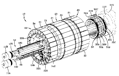
[0042] With reference to FIGS. l and 2, the radially expansible assembly drum
10 of the
present invention is illustrated. The drum 10 has a unique drum core assembly
12 which
includes a spindle 120 connected to a driving shaft 13, which controls the
drum rotation,
a first external shaft 140 which controls the radial expansion, and a second
external shaft
160 that controls the axial expansion or contraction of the drum 10. The first
external
shaft 140 and the second external shaft 160 is driven by a differential clutch
assembly
11. The first external clutch mechanism 11A controls the first external shaft
140, while
the second external clutch mechanism 11B controls the second external shaft
160A. The
drum 10 includes an outboard assembly 24, a center assembly 20 and an inboard
assembly 22. The radially outer surface of these assemblies 20, 22, 24 provide
a
receiving surface 21 upon which a tire can be built. The receiving surface 21
has ends
23, which include the inboard assembly 22 and the outboard assembly 24. The
entire
receiving surface 21 is radially expandable as well as being axially
contractible in such a
fashion that an entire first and second stage assembly of a tire can be
conducted on the
assembly drum 10 as illustrated. The entire assembly drum 10 and drum core
assembly
12 is bolted at location 110 to a tire building machine 112, which provides
rotation of the
primary shaft or spindle 120. Directly in front of the tire building machine
attachment
.. . . . ~.location..110.. is . shown. an. encoder assembly.3Ø... This three-
way encader.assembly 3 0
includes sensors 31A, 31B, 31C, an annular encoder disk 32A, 32B, 32C, each
annulax
disk having a readable surface 33A, 338, 33C, respectively. The encoder 30
provides a
way of identifying the location of the first external shaft 140 relative to
the spindle 120
utilizing one of the sensors 3 1A and one of the disks 32A. A second sensor
31B and disk
32B is used to locate the angular displacement of the second external shaft
160 relative
to the spindle 120, and the third encoder sensor 31C and annular disk 32C with
readable
surface 33C is provided to identify the absolute angular displacement of the
spindle 120.
In this way, the exact location anguiarly of each shaft 120, 140 and 160 is
known by the
combination of sensors. This relative position of the three shafts 120, 140,
160 insures
CA 02419525 2003-02-19
_9_
that the exact location of the equipment is precisely known at all times. This
enables a
computer to establish the precise location of the mechanism at any point in
time using
real time software. The reason this becomes an important feature of this type
of radially
expansible assembly drum 10 is due to the fact that through a unique way of
radial
expansion, this drum IO has the capability of providing almost an infinite
number of
diametrically expansible locations within a prescn'bed range as will be
discussed later.
This capability enables this drum 10 to build any number of tire sizes in any
number of
combination of diameters. It further enables the ends 23 to be provided with
different
diameters such that different bead diameters can be provided to build tires
having unique
bead diameters on the left side of the tire relative to the right side of the
tire. For most
applications, tires are symmetrical wherein the beads actually have the same
diameter.
In some tires, however, the beads may be of a different diameter creating an
asymmetric
construction. In such a case, it is important that the annular building drum
be provided
in such a way that it can accommodate different diameter bead cores. As will
be
discussed later, this radially expansible assembly drum 10 provides a way in
which such
tires can be easily manufactured in a precise manner.
[0043] With reference to FIG. 3, the drum core assembly 12 is shown in an
exploded
perspective view with the encoder means 30 being shown separated from the drum
core
assembly 12. The drum core assembly 12 as shown has a spindle 120, which is
attached
to the tire building machine 112 through the support mechanism 110 as
illustrated. The
spindle 120 has a cross-section, which has three concave curvatures 420 as
illustrated.
Lying within two of the concave curvatures 420 is the first external shaft 120
and the
second external shaft 160. As illustrated, guide-rails 130 are shown in each
location
adjacent the concavities 420 on the spindle 120. These guide-rails 130 provide
a
physical attachment for the outer assembly 221, center assembly 20 and inboard
assembly 22 of the radially expansible assembly drum 10, and provide for
linear
movement of the ends 23 of the outboard and inboard assemblies along these
guide-rails
130.
[0044) With further reference to the first external shaft 140, the entire
control of radial
expansion is transmitted thmugh this shaft. The shaft 140 as illustrated, has
a slot 148A
as illustrated, the slot I48A provides a key way for the spline gear
assemblies 142, which
are shown on each side of the shaft. The spline gear assembly 142 includes a
spline gear
which is keyed to the shaft slot 148A, a bearing housing 139 and a saline
sleeve 147
CA 02419525 2003-02-19
- 10-
which includes a ball spline nut 147A internal of the spline sleeve 147. The
spline sleeve
147 passes through the bearing 139 and is connected to the lock nut 141. The
combination of the pair of spline gear assemblies 142 and the shaft 140
provide radial
expansion of the assembly drum 10. At each end of the shaft 140 there is a
bearing
housing 144, including a bearing 145 as illustrated. The bearing housing 144
has
openings 465 as illustrated for attaching the shaft 140 directly to the
spindle 120 as
illustrated at the threaded holes 466
[0045] With reference to the second external shaft 160 as shown in the upper
portion of
FIG. 3, this shaft provides for the linear movement of the assembly drum ends
23
inwardly and outwardly. This movement is provided by having a threaded shaft
160
wherein the threaded shaft at one end 160A is oppositely threaded relative to
the shaft at
the other end 160B. These two shaft portions 160A and 160B are illustrated at
160A and
160B of the figure. The roller nut housing 167 includes a threaded bearing
166, called a
roller nut, that engages the threaded portion 160A or 160B of the shaft 160
and provides
linear movement for the assembly drum 10. One of these roller nuts housings
167 is
provided at each end of the shaft 160 and as previously discussed, they move
in opposite
directions when the differential clutch 11B is engaged and as the shaft 160 is
rotated, the
roller nut housings 167 move inwardly upon one rotation direction of the shaft
160 and
outwardly on an opposite rotation direction of the shaft 160. At each end of
the shaft
160 is attached a bearing housing 165 having an internal bearing 164, the
bearing
housing 165 has four openings 465 for which threaded fasteners can be provided
to
attach the shaft 160 to the spindle 120 as illustrated at the threaded holes
466.
[0046] With reference to FIGS. 4 through 18, a detailed discussion of the
outboard
assembly 24 and the inboard-assembly 22 follows. Throughout this discussion,
it is
important to note that the mechanisms of the outboard assembly 24 are
identical to those
of the inboard assembly 22, with the exception of accommodations for building
a tire
having different bead diameters. In those cases where the tire is built with
the same
diameter, the inboard and outboard assembly will be virtually identical only
facing in
opposite directions on the shaft 12 with the center assembly 20 interposed
therebetween.
In the example provided in the figures, the diameters of the outboard assembly
and the
inboard assembly, as it relates to the tire being constructed, are designed to
accommodate
tires of differem diameters relative to the inboard sidewall and the outboard
sidewall of
the tire.
CA 02419525 2003-02-19
-11-
[0047] With reference to FIG. 4, a turnup assembly 200 is illustrated on the
far left lower
corner of the figure. Adjacent to the turnup assembly 200 is shown a carrier
assembly
220. Adjacent to the carrier assembly 220 is a diameter control assembly 240.
Adjacent
the diameter control assembly 240 is a radially expandable segment set 260.
Adjacent
the segment set 260 is a seal assembly 280. The seal assembly 280 provides a
means for
covering the ends 23 of the outboard assembly 24 and the inboard assembly 22.
As
shown, the sealing assembly 280 can be a flexible membrane.
[0048] Attention is drawn to the FIG. 5 wherein the turmxp assembly 200 is
shown in
detail in an exploded view. Each turnup assembly 200 includes a plurality of
turnup
segment sets 212, a cam ring 202 on which the sets 212 rest. Each turnup
segment set
212 includes a linkage assembly 210. The linkage assembly 210 includes a
follower
block 213, an anchor block 209 and a pair of linkage arms 215. The follower
block 213
is rigidly attached to the axially outer portion of the segment set 212. At a
radially inner
location the cam follower 211 is attached to the cam follower block 213 in
such a way
that the cam follower 211 rides along the cam surface 202. As the cam follower
211
rides along the surface 202, it raises the cam follower block 213 moving the
entire
segment 212 radially outwardly as it is traversed radially inwardly. The cam
follower
block is connected to an anchor block 209 by a link arm mechanism having a
pair of link
arms 2I5, the link arms 215 are attached to both the follower block 213 and
the anchor
block 209 by a plurality of bearings sets, having bearing 219, lock washer
217, and
screws 218 holding the bearings in place. This enables the link arm 215 to
pivot
providing the necessary movement of the segment sets 212.
[0049] With further reference to FIG. 5 in the upper right-hand portion is
shown a pusher
ring 214. Attached to the pusher ring 214 are three cylinders 216: These
cylinders 216
are attached to the pusher ring 216 and as are further illustrated in FIG. 4,
the cylinders
are attached to the linear bearings 242. As illustrated in the end view of
FIG. 6, the
linear bearings 242 connect with the guide rails 130 to provide linear
movement of the
segments 212 during an operation known as a turn-up during the assembly of the
tire.
There are 24 equally spaced turn up segments 212. As shown, these segments are
dually spaced around the peripheral surface of the cam ring 202. A linear
actuation of
the cylinders 216 causes the cam follower bearing 211 to roll on a cam surface
of the
cam ring 202, which then moves the linkage assembly 210 to lift the outer
porn~n of the
CA 02419525 2003-02-19
- 12-
turn-up segment 212 to move it both radially outwardly and to move it
laterally inwardly
to effect a turn-up of the tires ply and liner.
[0050] With reference to the radially expandable assembly drum 10 as shown in
the
cross-sectional view of FIG. 7, all of the previously discussed components are
shown in
the assembly. In addition to the previously mentioned components, a drive gear
13A is
shown, which is adapted to fit in the center of the main drive shaft 120, this
gear 13A is
shown connected to the drive clutch 11 A. Along lines 8-8 of the cross-
sectional view of
FIG. 7 is shown a cam disk 245. As illustrated in FIG. 8, cut into the cam
disk 245 is a
spiral groove 243. The spiral groove 243 is cut on a constant rate increasing
angle such
that a 360° rotation of the drum creates a 40 mm diametrically outward
movement from
an initial 0° location to the 360° location. As shown, the drum
10 actually can rotate
beyond 360° relative to the axis of drum rotation in such a fashion
that the disk 245 as
shown can radially expand along the cam follower groove 243 to a diametrical
increase
of 50 mm.
[0051] FIG. 9 shows a cross-sectional view of the cam disk 245 with the cam
follower
groove 243. FIG. 10 shows a perspective view of the cam follower disk. It is
understood that both the inboard and outboard assemblies 22 and 24,
respectively, each
have a cam follower disk.
[0052] With reference to FIG. 11, the cam follower disk 245 is shown as part
of the
diameter control assembly 240. Outward of the cam follower disk 245 is shown a
bearing sleeve 249 which presses up against the cam follower disk 245 and
covers a pair
of bearings 252 illustrated at FIG. 18, the bearing sleeve 249 abuts up to the
gear 244 as
illustrated, emire assembly is then retained by the lock ring 253 shown
internal of the
gear '244.
(0053] With reference to FIG. 12, a support ring 250 is shown. Interposed
between the
support ring 250 and the cam disk 245 is shown a plurality of slide assemblies
247. In
between each slide assembly 247 is a keeper or retaining spacer 251.
[0054] With reference to FIGS. 13 and 14, two perspective views are shown of
the
diameter control assembly 240. In FIG. 13, the cam disk 245 is removed
exposing the
mechanisms that provide for radial expansion of the drum 10. The slide
assembly 247
has a cam follower bearing 248. The cam follower bearing 248 is designed to
fit in the
spiral groove 243. As shown, the cam follower bearings 248, as one traverses
counter-
clockwise around the view of FIG. 12, increases in radial displacement
outwardly. Thi c
CA 02419525 2003-02-19
-13--
radial displacement increase of the cam follower bearings 248 is designed to
the same
exact increase in the spiral cam follower groove 243. This insures that as the
drum 10
rotaxes, each cam follower 248 is moved precisely the same radially dimension
outwardly, or inwardly as the case may be. By doing this, the radially outer
surface of
the slide assemblies 24? all precisely move at the same rate; therefore, every
movemem
of the drum creates an exact and precise diameter at every location
360° around the
drum's outer surface 21. This is true upon any angular movemern of the drum,
inwardly
or outwardly. This feature provides the assembly drum 10 with an infinite
number of
preselected diameters within a prescribed range of the spiral groove 243.
[0055] With reference to FIG. 14, the backside of the assembly 240 is shown
wherein
the slide assembly is 247 are shown spaced by the retaining spacer 251. As
shown from
the backside, the retaining spacers 251 effectively are all positioned on a
radial line that
intersect the exact axis of rotation of the drum 10. The slide assemblies 247
then slide
between these retaining spacers 251 on a radial movement outwardly or
inwardly,
depending on the rotation ~f the drum 10. As shown, linear bearings 242 are on
the
radially inner surface of the assembly 240. These linear bearings 242 provide
for axial
movement or linear movement inwardly or outwardly as required.
[0056] FIGS. 15 and 16 further illustrate side and end views of the diameter
control
assembly 240, while FIG. 17 shows the opposite side of the diameter control
assembly
240 and along lines 18-18 of FIG. 17 is a cross-sectional view of FIG. 18,
showing all of
the internal mechanisms of this diameter control assembly 240. As shown, the
ca.m disk
245 has the spiral groove 243 illustrated with the cam follower bearing 248
shown
attached to the slide assembly 247 and located in a portion of the spiral
groove 243. The
bearing sleeve 249 presses against the cam disk 245 and the support ring 250,
thereby
holding in the slide assemblies 247 and the spacers 251. Directly underneath
the bearing
sleeve 249 are two roller bearings 252 that are retained by the bearing sleeve
249 and the
lock ring 253 as illustrated. Adjacent the bearing sleeve 249 is the gear 244.
Internal of
the diameter control assembly 240 is shown the linear bearings 242. These
bearings 242
are attached to the guide rails 130. These components make up the primary
features of
the assembly drum 10. When assembled, the diameter control assembly is
radially
inward of the radially expandable segment set 260, and the seal assembly 280.
[0057] As shown in Figure 19 at the center of the assembly drum 10, is a
center support
member 290. The center support member is mounted t~ the spindle 120 and
extends
CA 02419525 2003-02-19
- 14-
radially outwardly and has a cylindrically shaped outer surface having a pair
of annular
rings 292 on each side ofthe support member 290. Internal of annular rings 292
and
between the support member 290 are pairs of seals 284 and 282. Attached to the
support
rings is the flexible sealing member 280 on each side of the assembly drum 10.
Outward
of the assembly drum 10 is the center assembly 20. These features provide an
airtight
seal from which vacuum and pressure can be transferred to the components.
[0058) The sequence of drum operation for the building of a tire according to
the present
invention will now be described:
[0059) As shown in FIG. 19, an innerliner 40 is first applied to the radially
outer surface
21 of the assembly drum 10, otherwise known as the receiving surface 21.
Preferably, a
vacuum is applied to one center deck segment 262 of the drum to hold the
leading edge
of the innerliner 40 to the drum 10. The entire drum 10 rotates to apply the
innerliner 40.
One or two layers of innerliner 40 may be applied. Then a split chafer 44 is
applied on
both the left and right side of the inboard and outboard assemblies 22,24 of
the drum 10.
The exposed radial faces of the segments 262 and the inside lateral faces of
the turn-up
segments 212 form notches into which the split chafer 44 fits as illustrated.
The inside
edge of the split chafer 44 will overlap on the top of the outside edges of
the innerliner
44 as shown. The entire drum 10 rotates to apply the split chafers 44. After
application
of the split chafers 44, the outside diameter on the drum 10 along with the
turn-up
segments will present an approximately flat cylindrical surface for
application of
subsequent components.
[0060] Next, the ply stock 50 in one or two layers is applied. The ply stock
50 will
completely cover the inner liner 40 and the split chafers 44. The outer edges
of the ply
stock 50 vv~ll overlap on the top of the turn-up segments 212 at the outer
ends 23 of the
drum 10. The ply stock 50 may be preassembl~l with an outboard gumstrip and an
inboard gum strip aligned with the outboard and inboard edges of the ply.
Alternatively,
gum strips may be applied on the exposed radial faces of the turn-up segments
prior to
the applicaxion of the ply stock 50 on the drum 10. The ply stock 50 is
applied by
rotating the entire drum 10. Next, hard rubber inserts called talons 60 are
placed on top
of the ply stock 50 on both the left and right diameter control mechanisms
240. The
outside vertical faces of the talons 60 are positioned just axially inside of
the inside faces
of the turn up segments 212. The outside vertical faces on the talons 60 will
define the
CA 02419525 2003-02-19
-15-
line of folding for the ply turnups: The talons 60 are applied by rotating the
entire drum
10. After application, the joining ends of the talons 60 are stitched.
[0061] Next as illustrated in FIG. 20 a slight increase of the diameter of the
left diameter
control assembly 240, and the right diameter control assemblies 240 is
accomplished to
increase the hoop tension in the talons 60. The diameter control assemblies 20
are
operating simultaneously via common rotating ball spline shaft 140. The ball
spline
shaft 140 imports a rotation to the spiral cam disk 245 in each diameter
control section
240 relative to the overall drum. The rotation of the spiral cam disk 245
causes the radial
motion of the slide assemblies 247 supporting the individual drum segments
240. The
set of center deck segments 270 rest on the outside of the flexible sleeves
280 of the left
and right diameter control assembly 240, so the radial movement of the decks
270 will
follow the diameter of the diameter control assembly 240. This motion is
typical for all
diameter changes of the drum 10.
[0062] With reference to FIG. 21, the turn up of the ply endings over the
talons 60 is
accomplished as illustrated. The turn-up action is initiated by actuating air
cylinders 216
which move a common pusher ring 214, on each turn-up section, the motion of
the
pusher rings 214 causes the numerous turn-up segments 212 to move
simultaneously.
Due to the shape of the common cam ring 202 on each of the turn up sections
212, the
initial movement is radially outward followed by progressively more axial
motion. The
overall motion causes the ply endings to be forced up and over the talons 60
and on to
the ply stock 50. Once the tum-ups are affixed to the ply stock 50, the air
cylinders 216
are reversed causing the pusher rings 214 to move in the opposite direction
thereby
retracting the turn-up segments 212.
[0063] _ With reference to 'FIG. 22, the next sequence of the tire Building
requires the
beads 70 and 72 to be moved over the drum 10 in an axial direction. The beads
70,72 are
positioned directly above the bead pockets 2?4,275 formed in the segments 262
of the
diameter control sections 260. Once the beads 70,72 are positioned directly
over these
pockets or grooves 274,275 formed by the segments 262, then the diameter is
increased
on the left and right diameter control sections 240 until the smaller bead 70
is just
making contact with the turai up on the outside of the folded ply 50. As the
bead 70
makes contact with this ply turn up, the support mechanisms or arms 270
disengage
deflecting radially inwardly of the segments 262. These features will be
discussed later
and are as shown in FIGS. 27A, 27B, 28A, 28B and FIGS. 29A and 29B. After the
CA 02419525 2003-02-19
- 16-
smaller bead 70 makes contact, the diameter of the left and right control
sections is
increased further until the larger bead is making contact with the gum strip
on the outside
of the folded ply 50: At this point in time, the support mechanisms or arms
270 are
disengaged, deflecting to allow the larger bead diameter to fully engage into
the bead
pocket 275. At this point, this increase in diameter enables both beads 70,72
to be fully
seated in their respective bead pockets 274,275.
[0064] With reference to FIG. 23, the remaining components of the tire
carcass,
including, but not limited to an apex, a split chafer joining with the exposed
face of the
split piece of split chafer applied earlier, and sidewall material is added
and the entire
drum 10 is rotated for application of these components. This is further
illustrated in
FIGS. 24 and 24A.
[0065] With reference to FIG. 25, a previously manufactured belt 54 and tread
52 shown
in dash lines can be placed over the axial and radial center of the drum 10.
This can be
accomplishes via a tread and belt support ring on the tire building machine
112 not
shown. The tire building drum 10 is then decreased in bead width setting by
operating a
common roller screw 160 which controls the axial position of the left and
right diameter
control assemblies 240, as well as the turn up mechanisms 2U0. As the left and
right
diameter control assemblies 240 are moved axially inwardly, they slide
underneath the
outside edges of the multiple center deck segments 270. During this operation,
air is
injected into the chamber formed by the internal air seal 280 in the drum 10,
the inside of
the inner liner 40 of the tire 2, and the flexible sleeves 280 on the left and
right diameter
control assemblies 240. It is noted that the innerface of the bead sections of
the tire
carcass and the flexible sleeves 280, at this point in the tire building
assembly have been
drivewdown into thwbottom of the bead pockets 274,275 forming airtight seals.
The
combined axially inward motion of the beads 70,72 with the inflation air will
cause the
center of the tire 2 to expand diametrically to meet the inside diameter of
the tread belt
54 and tread 52. Alternatively, once the tire 2 is fully inflaxed, the tread
52 and belts 54
can be applied using a server and rotating the entire drum assembly. The tread
and belt
assembly is then stitched as required. The tire 2, once assembled, is easily
removed from
the drum 10 by decreasing the diameter of both diameter control assemblies
240. The
mounted and assembled tire 2 is shown in FIG. 26.
[0056] For a further detailed explanation of the diameter control assemblies
240 ability
to move the radially expandable segment assembly 260, attentioxi is drawn to
FIGS. 27A
CA 02419525 2003-02-19
-17-
through 29B. With reference to FIG. 27A and 27B, the segment assembly 260 is
illustrated. The segment assembly 260 has a plurality of segments 262. As
shown, each
segment 262 has a anchoring groove 264 cut on one side. When the segments
262are
aligned, the bead pocket 274,275 forms an annular groove for accepting the
beads 70 or
72. With reference to FIG. 27A a support arm 270 is shown adjacent each
segment 262
and interposed therebetween. The arm 270 in the fully upright position
provides
additional support for the tire 2 as it is being assembled. On the opposite
side of the
pocket 274 is an end face 265.
[0067] With reference to FIG. 27B, the arms 270 are shown in the retracted
position
exposing the full bead pocket 274;275 for receiving the bead 70,72. Each
segmem 262
has a slide link 269 that is attached to a linear bearing 271. The linear
bearing 271 is
captured in the segment 262 as shown. This slide link 269 and linear bearing
271
provide movement enabling the arm 270 to retract. This is accomplished by the
mid link
266, which is attached to the arm 270. The arm 270 is attached to the mid link
via. pin
273 and is further attached by a pin 273 to the segment 262 as shown. The
slide pin 268,
as shown, acts as guides to insure that the segments 262, when radially
expanded,
maintain a radial direction as the drum 10 approaches a fully expanded
position.
[0068] With reference to FIGS. 29A and 29B, the arm 270 is shown in the
upright
position for tire assembly, and is shown in the retracted position for bead
mounting. As
illustrated, the slide mechanism 269 moving along the linear bearing 271
retracts moving
the slide pin 268 approximately a distance D as illustrated. As the slide pin
268 moves
back, the mid-link arm 266 pulls the arm 270 into the retracted position
swinging the arm
270 in an angular motion approximately an angle alpha as illustraxed. This
fully exposes
the bead pocket 274. This embodiment, ~as shown, provides for support of the
tire
components as they are being mounted and prior to attaching the bead 70,72.
Once the
bead 70,72 is attached, it locks and secures the assembled tire components
into position.
[0069] Alternatively, the sealing member 280 can be simply attached over the
segments
262 and no arm mechanism may be required. In such a condition, the membrane
280
simply spans the pocket forming groove 274 and enables the tire 2 to be built.
While this
does not provide much support on applying the components, it is believed that
addition
of the bead will provide adequate stitching at that point in time where the
drum 10 is
fully expanded causing the bead to press the assembled tire components tightly
together.
CA 02419525 2003-02-19
-18-
[0070j As illustrated, the radially expandable assembly drum 10 permits the
tire 2 to be
built all the way through first and second stage tire building wherein the
tread 52 and belt
reinforcing structure 54 can be applied to this assembly drum 10 enabling the
tire 2 to be
completely finished and ready for vulcanization in a tire curing mold.
[0071j Variations in the present invention are possible in light of the
description of it
provided herein. While certain representative embodiments and details have
been shown
for the purpose of illustrating the subject invention, it will be apparent to
those skilled in
this art that various changes and modifications can be made therein without
departing
from the scope of the subject invention. It is, therefore, to be understood
that changes
can be made in the particular embodiments described which will be within the
full
intended scope of the invernion as defined by the following appended claims.