Note : Les descriptions sont présentées dans la langue officielle dans laquelle elles ont été soumises.
CA 02419604 2003-02-14
WO 02/15641 PCT/CA01/01184
TITLE SURROUND SOUND SYSTEM.
FIELD OF THE INVENTION
The present invention relates generally to musical
instruments and more particularly relates to surround
sound music systems. -
BACKGROUND OF THE INVENTION
On the production end, surround sound systems
typically include speakers, a recording console, and one
audio channel for each surround channel offered by the
recording console. The audio data from the various audio
channels is then decoded at the consumer end using a
surround compatible amplifier, a DVD player or a stand
alone decoder. In surround sound systems, the surround
compatible console can send different signals along
distinct audio channels to distinct speakers such that
different sounds will be emitted by distinct speakers.
As a result, a listener positioned so that distinct
speakers are in different directions, will hear different
sounds from these different directions, thereby creating
a three-dimensional type effect. This effect is
frequently used in movie-theaters, where the impression
of movement can be given by moving a sound, say a
helicopter sound, through a sequence of speakers spaced
throughout the sound environment.
These effects can be further enhanced through the
use of audio effector units. One example of an audio
effector unit is a electronic effect/delay unit, which
- 1 -
CA 02419604 2003-02-14
WO 02/15641 PCT/CA01/01184
can be used to create looping in which a sequence of
different notes or chords is played over and over again,
or a sustained note or group of notes sounded
simultaneously and continuously for varying lengths of
time (a drone). Optionally, this looping may be rendered
mufti-directional by moving the sequence between
different speakers. Specifically, sound can be "ping
ponged" back and forth between different speakers, or may
be circulated through different speakers. Sound may be
instantaneously switched between different speakers or
may be "panned" between different speakers where channels
to different speakers are sequentially and continuously
opened and closed to have the effect of sound dying out
at one speaker while it is being transferred to another
speaker. The electronic effect/delay unit has a mono
input linked to the surround compatible console or
directly to a miked instrument, and a mono or stereo
output through which, via the surround compatible
console, the unit can be connected to different speakers
via different output audio channels.
Other effector units include units that provide
sampling, looping, harmonizing, delays, reverberation and
infinite repeat loops. For example, harmonizers can
provide reverberation, delay and can also harmonize.
Samplers can be used to provide alternative sound sources
that are triggered by the guitar via voltage to midi
converters. For example, a guitar note received by a
sampler via a mono input could be converted by the
sampler into another musical note exclusive of a guitar,
say a piano note. These new sounds are then sent to the
- 2 -
CA 02419604 2003-02-14
WO 02/15641 PCT/CA01/01184
surround compatible recording console and from there can
be sent anywhere in the surround environment.
At their present stage of development, surround
sound systems permit the enhancement and modification of
previously created music. However, surround sound
technology has not been integrated into the initial
creation of the music, except where music is created by
re-mixing previously created music. Specifically, the
musician has not been able to play with directing
individual components of the music between different
speakers when actually creating the music. Accordingly,
a surround sound musical instrument that enables
musicians to use surround sound technology in the actual
creation of the music is desirable.
SUMMARY OF THE INVENTION
An object of an aspect of the present invention is
to provide an improved sound generation system.
In accordance with an aspect of the present
invention, there is provided a sound generation system
for providing surround sound via a plurality of spaced
speakers. The sound generation system includes a sound
generation means for operation by a user to generate
sounds. The sound generation. means has a plurality of
interface members for generating sounds. Each interface
member is operable by the user to generate an associated
sound. The sound generation system further includes a
plurality of sound channels for receiving sound from the
- 3 -
CA 02419604 2003-02-14
WO 02/15641 PCT/CA01/01184
plurality of interface members. Each interface member in
the plurality of interface member is connected to a
distinct associated channel in a plurality of sound
channels that transmit the associated sound to the
distinct associated channel. Further, the sound
generation system includes a sound-directing means for
allocating the associated subset of sounds for each sound
channel in the plurality of sound channels to at least
one speaker in the plurality of spaced speakers. The
sound-directing means is connected to the plurality of
sound channels and is connected to.: the plurality of
speakers via a plurality of speaker channels.
Preferably, the sound generation means is a musical
instrument. Conveniently, this musical instrument is a
stringed musical instrument, and the plurality of
interface members are a plurality of strings of the
musical instruments.
In accordance with a second aspect of the present
invention, there is provided a sound generation system
for providing surround sound. The sound generation
system includes a sound generation means for operation by
user to generate sounds. The sound generation means has
a plurality of interface members for generating sounds.
Each interface member is operable by the user to generate
an associated sound. A sound generation system also
includes a plurality of sound channels of receiving sound
from the plurality of interface members. Each interface"
member in the plurality of interface member is connected
to a distinct associated channel in the plurality of
- 4 -
CA 02419604 2003-02-14
WO 02/15641 PCT/CA01/01184
sound channels to transmit the associated sound to the
distinct associated channel. The sound generation system
further includes recording means for recording sound from
each channel in the plurality of sound channels.
Preferably, the recording means includes a plurality
of ports for receiving the plurality of sound channels.
Each channel in the plurality of sound channels is
connected to an associated port in the plurality of
ports. The recording means also includes a replay means
for transmitting the sound recorded from each channel in
the plurality of sound channels via a selectable port in
the plurality of ports.
BRIEF DESCRIPTION OF THE DRAi~7INGS:
Reference will now be made, by way of example, to
the accompanying drawings, which show preferred aspects
of the present invention, and in which:
Figure l, in a schematic view, illustrates an
embodiment of a musical instrument component of a
surround sound system in accordance with the preferred
embodiment of the present invention;
Figure 2, in a schematic view, illustrates an aspect
of a mult/patch bay component of the surround sound
system of Figure 1;
Figures 3 and 4, in schematic views, illustrate
audio effect aspects of a sound processing component of
- 5 -
CA 02419604 2003-02-14
WO 02/15641 PCT/CA01/01184
the surround sound system of Figure 1; and,
Figure 5, in a schematic view, illustrates an aspect
of a surround compatible console component of the
surround sound system of Figure 1.
DETAILED DESCRIPTION OF PREFERRED ASPECTS OF THE
INVENTION
When an audio engineer or a film sound mixer uses a
surround sound system it is generally to place special
audio effects into the 3-D realm or for mixing sound to
create greater ambience in pre-recorded program material.
For instance, a jazz quintet could be mixed to have the
piano emanating from one speaker, the bass from another,
the vocals from yet another and so on. This can be
referred to as 3-D mixing, and creates an atmospheric
ambience in the recording. However, none of the
individual instruments can be played or recorded three
dimensionally on their own. In contrast and in
accordance with an embodiment of the present invention,
each of the strings of an instrument can be allocated to
its own audio channel, and hence placed anywhere in a 3-D
surround spectrum.
Referring to Figure 1, there is illustrated a
Littler guitar 20 having six strings 22. The Littler
guitar is an electrical guitar invented in the late 1970s
by Allan Littler and is described in U.S. Patent No.
4,079,652, which is incorporated by reference. The
Littler guitar 20 has six linear pickups 24. Six guitar
- 6 -
CA 02419604 2003-02-14
WO 02/15641 PCT/CA01/01184
output lines 26 are linked to the Gittler guitar 20.
Each one of the guitar output lines 26 is linked to a
separate linear pickup 24. Each of the guitar output
lines 26 is linked to a pre-amplification module 28 that
brings the signal from the low impedance guitar up to an
acceptable level. This signal is then output from the
pre-amplification modules 28 via pre-amplification
outlets 30.
Referring to Figure 2, pre-amplification outlets 30
are shown connected to a mult/patch bay unit 32. The
mult/patch bay unit 32 takes the input signals from the
pre-amplification outlets 30 and creates multiple outputs
of the same signal for each of the input signals. These
multiple output signals are output via mult output lines
34, each of which can be directed to distinct processors.
In Figure 2, three distinct mult output lines 34 are
shown for each of the strings of the guitar; however, for
ease of representation, these three distinct mult output
lines 34 for each string of the guitar are eventually
reduced to one mutt output line 34 for each string of the
guitar. This total of six mult output lines 34 are then
further reduced, at the right-hand side of Figure 2, to
a single mutt output line 34, and then expanded again to
a total of three mult output lines 34. In the actual
embodiment, these mult output lines 34 would all be kept
separate - there would be eighteen (three for each of the
six strings) mutt output lines in total.
As a result of having a distinct pickup for each
string 22 of the guitar ~20, the notes from different
-
CA 02419604 2003-02-14
WO 02/15641 PCT/CA01/01184
strings can be assigned to different audio inputs on a
recording console and from thence to different speakers.
The fac-t that sound and music created by different
strings can be directed to different speakers and heard
by a listener from different directions, gives a listener
within the surround environment the impression of being
inside the instrument itself. Further, the fact that the
musician can individually and dynamically control the
direction from which the listener will hear the notes
from each individual string makes the surround
environment a part of the performance of the music. In
other words, the musician is able to redirect sounds from
different strings to different speakers to vary the
overall musical effect.
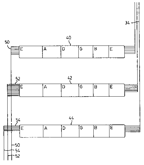
The notes from each string can be processed in
multiple ways due to the generation of multiple signals
for each string by the mult/patch bay unit 32. Referring
to Figure 3, various audio effector boxes for processing
the signal received from each of the strings are
illustrated. One of the audio effector boxes permits
sampling. Specifically, six of the mult output lines 34
lead into a midi converter 40 that converts the six
voltages into midi. Using the midi converter 40, the
guitar 20 can be used to trigger any combination of
sample sounds stored on a sampler associated with the
midi converter 40. Specifically, by playing a specific
note on a specific string, and transmitting the signal
thus generated to the midi converter 40, a sample sound
not conventionally playable by a guitar, such as a piano
sound say, can be triggered by the midi converter 40
_ g _
CA 02419604 2003-02-14
WO 02/15641 PCT/CA01/01184
sending a midi signal to the sampling unit.
Six of the mult output lines 34 lead into a
sampling/signal processor 42. This processor 42 has a
mono or stereo input for each string, and a stereo
output. Accordingly, although there are six mult outputs
leading into the processor 42, twelve processor output
lines 52 lead from the processor 42: Using the processor
42, looping can be created. Optionally, this looping may
be rendered multi-directional by moving the sequence
between different speakers. The signals generated by the
processor 42 are then output via processor output lines
52.
Six mult output lines 34 lead into harmonizer 44.
Harmonizes 44 also creates loops, and can also, for any
note received as an input, provides reverberation, delay
and harmonization. Harmonizers harmonize by playing a
note at some specific interval above the first note
received.
The midi converter 40, processor 42 and harmonizes
44 are all examples of audio effector boxes that take an
audio signal and manipulate that signal or generate new
signals based on the signal received before releasing an
output. Many different kinds of audio effector boxes can
be used. Combining these audio effector boxes with the
ability to direct different sounds generated
simultaneously from the same guitar to different guitar
output lines 26, exponentially increases the creative
freedom of the musician, in that the musician is not
- 9 -
CA 02419604 2003-02-14
WO 02/15641 PCT/CA01/01184
only able to direct different notes played to different
speakers, but is also able to process these different
notes differently before transmitting the processed notes
from each speaker.
Referring to Figure 4, a sampler 58 for the midi
converter is illustrated. Specifically, midi output
lines 50 are connected to the sampler 58 at a midi input
of the sampler 58. At the midi converter 40, notes from
the guitar 20 were converted into digital signals. These
digital signals are then transmitted to the sampler 58
via midi output lines 50. At the sampler 58, the digital
signals are then converted into musical notes that may be
exclusive of a guitar, such as, say, a piano note. These
audio signals are then output via sampler output line 60.
Referring to Figure 5, sampler output line 60, processor
output lines 52, and harmonizer output lines 54 are all
fed into a digital surround compatible console 64 that is
used to mix the 3-D sounds and to allocate these sounds
to any speaker in the surround environment. The up to
sixteen sampler signals, twelve processor signals and six
harmonizer signals are then transmitted to the speakers
via audio channels 70, 72 and 74 respectively.
It will be appreciated by those skilled in the art,
that the particular audio effector boxes used, indeed the
use of any audio effector boxes, are not essential to the
invention. They merely demonstrate some of the
advantages flowing from the implementation of the'
invention. The invention could also be implemented by
linking guitar output lines 26 directly to the surround
- 10 -
CA 02419604 2003-02-14
WO 02/15641 PCT/CA01/01184
compatible console 64, without either the speakers or the
audio effector boxes. Then, once the, music had been
recorded, the musician can interact with the recorded
music by directing different parts of the instrument to
different speakers. Alternatively, the invention could
be implemented by linking guitar output lines 26 directly
to the surround compatible console 64 and from thence to
the speakers. The musician would still be able to direct
individual notes from individual strings to different
speakers, thus enabling the musician to play with this
surround environment as an inherent part of the creative
process.
Surround compatible console 64 is a means through
which to channel the notes of an electronic instrument
(or the strings of a Littler guitar) to the various
amplifiers and speakers in the surround environment.
This allows one to take a plurality of analogue signal
sources, convert them to the digital domain, manipulate
them and direct them to the surround environment. The
signals are then reconverted to analogue signals and sent
out the auxiliary outputs (sends) to the amplifiers and
speakers.
Tn another embodiment, this process can be achieved
within a software program referred to as a recording
platform. Digital audio recording platforms may
incorporate an internal mixing console and may support
surround mixing options. To use this approach in the
present invention another piece of hardware, namely an
analogue to digital, digital to analogue converter may be
- 11 -
CA 02419604 2003-02-14
WO 02/15641 PCT/CA01/01184
used. In a preferred' embodiment, a minimum of six inputs
and six outputs are used. The number of inputs and
outputs may vary to correspond with the manner of
surround sound system used, and could include various
numbers of channels and sound sources.
In another embodiment, the invention includes
hardware such as a joystick or a programmable midi
controller as a means of manipulating the individual
channel's location in the surround environment. Such
digital audio platforms allow one to take recorded
material and mix it into the surround environment. Thus,
sounds that are being input into the recording platform
can be manipulated at will during a performance. Thus
the present invention teaches a three dimensional sound
generating device.
It will be further appreciated by those skilled in
the art, that although the foregoing description is of
aspects of the invention as implemented using a Littler
guitar, the invention might well be implemented using
other musical instruments by permitting different notes
from these musical instruments to be directed to
different speakers. For example, on a keyboard,
different notes might be allocated to different speakers.
Specifically, whenever a musician performs a distinct act
by, say, striking a particular key on a keyboard, or a
string on a guitar, the musician playing an instrument in
accordance with the present invention could also direct
the sound resulting from this act to a specific speaker.
Accordingly, other variations and modifications of the
- 12 -
CA 02419604 2003-02-14
WO 02/15641 PCT/CA01/01184
invention are possible. All such modifications or
variations are believed to be within the sphere and scope
of the invention as defined by the claims appended
hereto.
- 13 -