Note : Les descriptions sont présentées dans la langue officielle dans laquelle elles ont été soumises.
CA 02419611 2003-O1-29
IVSW-429
27.07.2000/7119
Cable, in particular underwater cable
- Description . .
The invention concerns a cable, ~in particular an
underwater cable, according to the precharacterizing
clause of Claim 1.
Underwater cables (so-called submarine cables) must be
observed during laying, for inspection purposes and for
tracing any defects. This takes place under water.with
remote-controlled cameras. The pictures taken by the
cameras under water, in particular at great depths,
often allow the underwater cable to be made out only
with difficulty, in particular whenever it has a
customary black or dark outer sheath. This makes it
difficult in particular to locate defective underwater
cables.
~ Setting out from the above.situation, the invention is
based on the object of providing a cable, in particular
an underwater cable tsubmarine cable), which can be
made out well under water, even at great depths.
A cable serving to achieve this object, in particular
an underwater cable or submarine cable, has the
features of Claim 1. At least one externally visible
marking of a different colour on the outer sheath makes
the cable more easily visible, in particular in the
underwater area. The underwater cable according to the
invention can be made out more easily. on camera
pictures, because the marking of a different colour
provides the outer sheath with greater contrast.
The marking can be formed in a wide variety of ways.
The marking preferably consists of one or more strips
or lines extending continuously in the longitudinal
direction of the outer sheath of the cable and
' CA 02419611 2003-O1-29
- 2 -
preferably extending spirally around the cable. The
marking comprising one or more spiral longitudinal
strips or longitudinal lines on the outer sheath has
the effect that the marking is always visible,
irrespective of from which side the cable is viewed.
Since submarine cables can turn about their
longitudinal axis during laying, the longitudinal
strips or longitudinal lines likewise running spirally
around the longitudinal axis of the submarine cable
'10 represent a marking that is virtually always visible.
It is alternatively also conceivable to form the
marking by transverse strips or transverse lines
running in a cross-sectional direction around the
cable. These are then im practice endless, coloured
rings around the outer sheath. They are also always
visible, irrespective of any turning of the cable. The
peripheral transverse strips or transverse lines have
the advantage that turning of the submarine cable .
during laying does not become visible and as a result
..does not disturb the viewer.
It is likewise conceivable to form the marking from
straight longitudinal strips or longitudinal lines. In
order that a straight longitudinal strip or
longitudinal line is always visible in each case, a
corresponding number of longitudinal strips or
longitudinal lines are arranged evenly distributed on
the circumference of the outer sheath. The
longitudinal strips or longitudinal lines or transverse
strips or transverse lines can also be produced from at
least one series of two-dimensional formations
following one another at intervals. The two-
dimensional formations may have any desired base areas,
and in particular be round, elliptical, square or
rectangular. Similarly, the intervals between the two-
dimensional formations may be as desired.
CA 02419611 2003-O1-29
_ 3 _
.Finally, it is also conceivable to provide the entire
outer sheath with a marking comprising dots of any
desired shape. In this case, the dots are arranged in
a uniform grid, which preferably extends over the
entire circumference of y the outer sheath. Such a grid
also has the advantage that the marking is always
visible and turns of the submarine cable during laying
do not become evident .and do not in this case detract
from the observation of laying.
Any type of marking can be formed by a dye sprayed or
printed onto the outer sheath after it has been
produced. For this purpose, a dye which is permanently
resistant to sea water is used. It is also
ZS conceivable, after applying the dye forming the
marking, to provide the entire outer sheath with a
transparent protective layer, which also covers the
coloured marking.
It is also possible to form the marking' from a plastic
of a different colour during the production of the
outer sheathf The outer sheath is.,.then made up of
differently coloured plastic materials. For example,
this can be achieved by coextrusion of the outer sheath
or by sintering the plastic of a different colour onto
the surface of the outer sheath. The types of marking
mentioned then have virtually the same sea-water
resistance as the outer sheath.
According to a preferred development of the invention,
the respective marking has a lighter colour than the
outer sheath. It is also advantageous if the lighter
colour of the marking has fluorescent properties. As a
result, the marking of the submarine cable becomes
visible even at great depths if searchlights of an
underwater camera shine on it.
In the case of submarine cables with a usually black
outer sheath, a yellow colour, in particular a
CA 02419611 2003-O1-29
' - 4 -
fluorescent yellow colour which offers easily visible
i contrast together with the black colour of the outer
sheath, is preferably chosen for the lighter colour of
the marking.
The marking may also be formed by mixing colour
particles or colour pigments in with the raw material
of the plastic for forming the outer sheath. Such an
outer sheath then has an essentially regular
distribution of coloured locations, in particular small
dots. The embedding of the colour particles or colour
pigments in the plastic material for forming the outer
sheath ensures a permanent bonding of the marking to w
the submarine cable.'
In an alternative development of the submarine cable
according to the invention, the marking is formed by a
netting applied to the outer sheath. The netting
surrounds the entire outer sheath and extends
uninterruptedly in- the longitudinal direction of the
submarine cable. The netting produces on the outside
of the outer sheath of the submarine cable peripheral
transverse strands and rectilinear longitudinal strands
with preferably a round cross section, although other
cross sections,- for example square, are also
conceivable. If the netting is of a different colour,
the crossing longitudinal and transverse strands form
the marking.
Preferred exemplary embodiments of the cable according
to the invention are explained in more detail below
with reference to the drawing, in which:
Figure 1 shows a portion of a submarine cable in a
side view,
Figure 2 shows a side view of a portion of a submarine
cable according to a second exemplary
embodiment of the invention,
CA 02419611 2003-O1-29
- 5 -
' Figure 3 shows the submarine cable of Figure 2 in a
side view turned through 90°,
Figure 4 shows a side view of a portion of a submarine
cable according to a third exemplary
embodiment of the invention,
Figure 5 shows a side view of the submarine cable of
Figure 4, turned through 90° with respect to
Figure 4,
Figure 6 shows a portion of a submarine cable
according to a fourth exemplary embodiment of
the invention, and
Figure 7 shows a portion of a submarine cable
according to a fifth exemplary embodiment of
the invention.
_The figures show cables for underwater use, namely
submarine cables of any desired construction. In
particular, the submarine cables. may have in the
interior a core of any desired construction. For
example, the core may have both electrical conductors
and optical waveguides or combinations of the two. In
addition, the core has at least one armouring or
reinforcement for protection against mechanical
influences. The core with the reinforcement or
armouring is surrounded by a closed outer sheath, which
consists essentially of plastic. The outer sheath is
usually black.
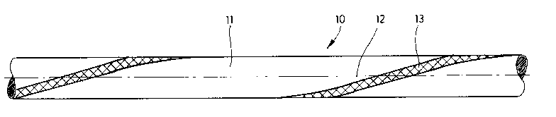
Figure 1 shows a submarine cable 10, the outer sheath
11 of which is provided with an externally visible
marking. In the exemplary embodiment shown, the
marking is formed by a longitudinal strip 13 running
spirally around the outer sheath 11 in the longitudinal
direction, in other words along the longitudinal centre
axis 12 of the submarine cable 10. The single
CA 02419611 2003-O1-29
- 6 -
longitudinal strip 13 in the exemplary embodiment of
Figure 1 has, depending on the diameter of the
submarine cable 10, a width of between 1 and 5 mm. The
longitudinal strip 13 preferably has a width which
corresponds approximately to one-quarter to one-fifth
of the diameter of the submarine cable 10. In the
exemplary embodiment shown, the pitch of the spiral
helix of the longitudinal strip 13 around the submarine
cable 10 is chosen such that, over a length of the
to submarine cable 10 which is approximately three to ten
times, preferably approximately eight times, the
diameter of the said cable, the longitudinal strip 13
has run once around the outer sheath 11 of the
submarine cable 10.
Figures 2 and 3 show a submarine cable 14 according to
a second exemplary embodiment of the invention. The
internals of the submarine cable 14 - which may be of
any desired construction - are not represented in any
more detail 'in the figures mentioned (or in any of the
other figures) . Only the outer sheath l5 with markings
according to the invention is shown. In the present
exemplary embodiment as well, the marking is formed by
longitudinal strips running in a serpentine manner
~25 around the outer sheath 15 along the longitudinal
centre axis 16, to be precise two longitudinal strips
17 and 18. For reasons of simple representation, the
longitudinal strips 17 and 18 are only indicated by
lines. In fact, they have a width which, depending on
the diameter of the submarine cable 14, may be between
1 and 5 mm. It is also conceivable to make the
individual longitudinal strips 17 and 18 of different
widths.
The two longitudinal strips 17 and 18 run in different
directions around the outer sheath 15. While the
longitudinal strip 17 snakes clockwise around the outer
sheath 15, the longitudinal strip 18 runs anti-
clockwise around the outer sheath 15. Both
CA 02419611 2003-O1-29
_ ')
.longitudinal strips 17 and 18 have the same pitch,
which is indicated in Figures 2 and 3 by the dimension
L. This means that, on a portion L of the submarine
cable 14, the longitudinal strip 17 wraps once right
around the submarine cable 14 in one direction and the
longitudinal strip 18 wraps once right around the
submarine cable 14 in the other direction. The
different wrapping directions of the longitudinal
strips 17, l8 around the submarine cable 14 lead in the
case of torsion or twisting of the submarine cable 14
to the. originally identical pitches of the two
longitudinal strips 17, 18 differing from each other.
In an extreme case, a longitudinal strip 17, 18 may
extend approximately in a straight line along the
submarine cable 14, while the other longitudinal strip
17, 18 runs around the sheath of the submarine cable 14
with a smaller pitch (in a serpentine manner). In this
way it is always ensured that one longitudinal strip 17
or 18 runs in a helical manner around the submarine
cable and, as a result, is constantly visible. In
addition, it can easily be visually established from
;:deviations in the pitches of the longitudinal strips
17, 18 to what extent the submarine cable 14 is
subjected to torsion or twisted.
The longitudinal strips 17 and 18, which follow an
identical path, cross at common nodes 19, the intervals
of which have half the dimension L of a complete
revolution of the respective longitudinal strip 17 and
18 around the outer sheath 15.
The design and arrangement described of the
longitudinal strips 17 and 18 on the submarine cable 14
have the effect that, depending on the viewing
direction towards the side of the submarine cable 14,
the two oppositely running longitudinal strips 17 and
18 have different paths. It can be seen from the
representation in Figure 2 that both longitudinal
strips 17 and 18 are simultaneously visible in the same
CA 02419611 2003-O1-29
_ g _
region of the length of the submarine cable 14.
Between two successive visible portions of the
longitudinal strips 17 and 18, both longitudinal strips
17 and 18 disappear entirely to the invisible rear side
of the submarine cable 14. The length of this
invisible region is half the length of one complete
revolution of the respective longitudinal strip 17 and
18 around the submarine cable 14. If the submarine
cable 14 represented in Figure 2 is viewed from below,
one of the two longitudinal strips 17 or 18 is alwayse_
visible. The serpentine or sinusoidal path shown in
the figure is thereby obtained. Thus, from certain
views of the submarine cable 14, the two longitudinal
strips 17 and 18 extending in opposite directions have
the effect that either only a single longitudinal strip
17 or 18 is visible or both longitudinal strips 17, 18
are only partially visible.
Figures 4 and 5 show a third exemplary embodiment of a
submarine cable 20, in which the marking has four
longitudinal strips 21 to 24. The longitudinal strips
21 and 22 correspond to the longitudinal strips 17 and.
18 of the exemplary embodiment of Figures 2 and 3. The
longitudinal strips 21 and 22 become visible in the
left-hand half of the dimension L of Figure 4. Located
invisibly behind them, with the same path, are the
longitudinal strips 23 and 24. In the right-hand half
of the dimension L in Figure 4, the longitudinal strips
21 and 22 disappear invisibly to the rear side of the
outer sheath 25 of the submarine cable 20. In this
region, the longitudinal strips 23 and 24 appear
visibly on the front side of the outer sheath 25.
Behind the dimension L in Figure 4, these strips
disappear again to the rear side of the outer sheath 25
and the longitudinal strips 21 and 22 visibly reemerge.
The longitudinal strips 21 and 22 on the one hand and
23 and 24 on the other hand are all of the same design
as one another. The longitudinal strips 21, 22, 23, 24
CA 02419611 2003-O1-29
9
wrap around the outer sheath 25 in the direction of the
longitudinal centre axis 32 of the submarine cable 20.
The only difference that, at the upper (left-hand) node
26 in Figure 4, the longitudinal strip 21 begins in one
direction and the longitudinal strip 23 begins in
another direction. Extending from the node 27 lying
below it in Figure 4 are the longitudinal strips 22 and
24, to be precise in such a way that they wrap around
the submarine cable 20 in opposite directions. As a
result, there are always two nodes 26 and 27
diametrically opposite one another on the outer sheath
25 of the submarine cable 20. The nodes 26 and 27 are
always offset by the dimension L-quarter in the
direction of the longitudinal centre axis 16 of the
submarine cable 20 and also always turned through 90°
The four longitudinal strips 21, 22, 23 and 24, which
are of the same design and are just directed
differently, or extend from different nodes 26 to 27,
achieve the effect that the marking of the outer sheath
is continuously visible from every side of the
.submarine cable .20, to be precise with the same
pattern, as clearly illustrated by Figures 4 and 5,
which show the submarine cable 20 from two viewing
25 directions respectively offset by 90°.
The longitudinal strips 21, 22, 23 and 24, again shown
only as lines in Figures 4 and 5 for reasons of
simplification, are in fact designed as wider strips,
to be precise with a width of preferably 1 to 5 mm. In
the case of relatively thick submarine cables 20, the
strips may be even wider. The same also applies to the
other exemplary embodiments of the invention. It is
conceivable to make the individual longitudinal strips
21, 22, 23 and 24 of different widths.
Figure 6 shows a fourth exemplary embodiment of a
submarine cable 28. This submarine cable 28 has on an
outer sheath 29 a marking comprising a multiplicity of
CA 02419611 2003-O1-29
1~
,round dots 30. The dots 30 are distributed uniformly
over the entire length of the submarine cable 28 along
its longitudinal centre axis 31 over the entire
circumference of the outer sheath 29. For this
purpose, in the exemplary embodiment shown, the dots 30
are arranged in a uniform grid. This is made up of a
plurality of rows of dots 30, following one another at
uniform intervals, the said rows extending parallel to
the longitudinal centre axis 16 and the dots 30 of
~10 adjacent rows being offset by half the interval between
pairs of dots 30, in other words are arranged such that
they are staggered. The interval between neighbouring
dots 30 is slightly greater than the diameter of the
same . The dots 3 0 , which are the same as one another,
have in each case a diameter of preferably 1 to 10 mm.
The interval between the dots 30 may also be greater
than their diameter; preferably, the interval between
the dots 30 is five to twenty times as great as their
diameter.
While the outer sheaths of the submarine cables shown
are black, the markings, in other words the
longitudinal strips 1.3 , 17 , 18 , 21, 22 , 23 , 24 , or the
dots 30, have a lighter colour. The longitudinal
strips 13, 17, 18, 21, 22, 23, 24 or the dots 30 are
made yellow. This may be a shade of yellow which has
fluorescent or retro-reflective properties.
It is also conceivable to provide in particular the
submarine cables 14 and 20 with a plurality of
longitudinal strips 17, 18 or 21, 22, 23 and 24,
respectively, as shown in Figures 1 to 5. The
individual longitudinal strips 17, 18, 21, 22, 23 or 24
may also be provided with different colours, which
however are to be significantly lighter than the black
colour of the outer sheaths. The dots 30 on the outer
sheath 29 of the submarine cable 28 may also be of
different colours.
CA 02419611 2003-O1-29
- 11 -
The markings are continuously applied to the outer
sheaths of the submarine cables while they are being
produced, or are made in the outer sheaths. This may
take place during or after the production of the
respective outer sheath.
After the production of the respective outer sheath,
the marking may be printed or sprayed onto the the
outside of the respective outer sheath in the form of
longitudinal strips 13, 17, 18, 21, 22, 23, 24 or dots
30. In this case, the marking is formed from a coating
of a corresponding colour or from liquid plastic. The
coating or the liquid plastic must be of such a nature
that it adheres well to the outer sheaths and is
indelible, even in salty sea water.
It is also conceivable to produce the marking by
sintering onto the respective outer sheath. This also
takes place preferably after the production of the
outer sheath. In this case, the sintering-on can be
performed while the outer sheath has not yet fully
cured.
The marking may also be produced during the production
of the respective outer sheath of the submarine cable,
by the respective outer sheath being formed from
plastics of different colours. Then the outer sheath
is formed, for example by the coextrusion process,
simultaneously from the black plastic and the
differently coloured, for example yellow, plastic for
forming the marking, in particular the longitudinal
strips 13, 17, 18, 21, 22, 23, 24.
The longitudinal strips 13, 17, 18, 21, 22, 23, 24
shown in Figures 1 to 5 extend continuously over. the
entire length of the respective submarine cable, in
other words snake constantly, that is to say repeatedly
or many times, around the outer sheath.
CA 02419611 2003-O1-29
- 12 -
. Figure 7 shows a submarine cable 33 in which the
marking is formed by a netting 34. The netting 34
surrounds the outer sheath 35 of the submarine cable
33. In the exemplary embodiment shown, the netting is
formed by longitudinal strands 36, extending in the
longitudinal direction of the submarine cable 33, and
transverse strands 37, directed transversely thereto,.
which surround the outer sheath 35 uninterruptedly. In
the present case, the interval between pairs of
10w neighbouring, parallel longitudinal strands 36 is
approximately the same size as the interval between two
neighbouring, parallel transverse strands 37. As a
result, rectangular openings 38 are created between the
longitudinal strands 36 and transverse strands 37. It
is also possible, however, to choose the intervals
between neighbouring longitudinal strands 36 to be less
or greater than the intervals between neighbouring
transverse strands 37. Similarly, the longitudinal
strands may also extend obliquely with respect to the
longitudinal axis of the submarine cable 33 or wrap'
around it in a serpentine manner. Such longitudinal
strands are also joined by transverse strands, which,
if appropriate, may extend obliquely with respect to
the longitudinal axis of the submarine cable 33 in
order that they intersect the longitudinal strips at
right angles.
The longitudinal strands 36 and transverse strands 37
intersect at nodes 39. At these nodes 39, the
longitudinal strands 36 are at the same time integrally
joined to the transverse strands 37. The longitudinal
strands 36 and the transverse strands 37 preferably
have round cross sections of the same size.
The netting 34 is applied to the outer sheath 35 after
the said sheath has been produced. For this purpose,
after extrusion of the outer sheath 35 onto the core of
the submarine cable 37, the netting 34 is extruded onto
CA 02419611 2003-O1-29
- 13 -
the outside of the outer sheath 35 in a second
extrusion step.
The netting 34 and the outer sheath 35 are preferably
formed from plastic, in particular an identical
plastic. With regard to colour, the netting 34 differs
from the outer sheath-35. . For example, the netting 34
is of a yellow colour, if appropriate with fluorescent
properties, while the outer sheath 35 is black. The
10' ' openingsv--~3 8y between the longitudinal , strands 3 6 and the
transverse strands 37 then appear black, while between
neighbouring openings 38 there is the yellow marking
formed by the . longitudinal strands 36 and the
transverse strands 37.
I5
As a departure from the exemplary embodiments shown,
the markings may take any other desired form. For
example, transverse strips, longitudinal strips which
extend in a straight line parallel to the longitudinal
20 centre axis of the submarine cable or dots with square
or non-round surface areas may be used. It is also
conceivable to form the longitudinal strips or other
strips by a row of dots following one another at short
intervals or to interrupt the continuous longitudinal
25 or transverse strips occasionally. In addition, it is
conceivable to vary the number of longitudinal strips
as desired or to combine longitudinal strips and dots
with one another.
30 An alternative development of the invention, not shown
in the figures but preferred, envisages providing the
outer circumferential surface of the submarine cable
not only with one or more spiral longitudinal strips
(fox example according to Figures 1-5? but also with at
35 least one longitudinal strip extending in a straight
line parallel to the longitudinal centre axis of the
submarine cable. The submarine cable is then provided
with both spiral and longitudinal strips. The straight
longitudinal strips allow twisting or torsion to be
CA 02419611 2003-O1-29
- 14 -
identified during the laying of the cable, in that the
straight longitudinal strip is also made to run
spirally with a relatively great pitch. When the
submarine cable has been laid, the spiral longitudinal
strip or strips then serve for allowing it to be
identified in any desired position under water.
~
CA 02419611 2003-O1-29
- 15 -
List of reference numerals
Submarine cable
11 Outer sheath a
12 Longitudinal centre axis
13 Longitudinal.. strip , .
14 Submarine cable
Outer sheath
16 Longitudinal centre axis
17 Longitudinal strip
18 Longitudinal strip
19 Node
Submarine cable
21 Longitudinal strip
22 Longitudinal strip
23 Longitudinal strip
24 Longitudinal strip
Outer sheath
26 Node
27 Node
28 Submarine cable
29 Outer sheath
Dot
31 Longitudinal centre axis
32 Longitudinal centre axis
33 Submarine cable
34 Netting
Outer sheath
36 Longitudinal strand
37 Transverse strand
38 Opening
39 Node