Note : Les descriptions sont présentées dans la langue officielle dans laquelle elles ont été soumises.
CA 02419647 2003-02-21
-1-
Walk-in refrigeration unit control and monitoring system
Field of invention
[0001 ] The invention relates to walk-in refrigeration units. More
specifically, the invention relates to the control and monitoring of various
parameters of walk-in refrigeration units.
Background of invention
[0002] The device described in US patent 6,401,466 B1 (hereby
incorporated by reference) is a good example of the present state-of-the-art
in
the field of walk-in refrigeration units. Many improvements can be made to
such existing devices to render walk-in refrigeration units more efficient.
[0003] There is therefore a need in the industry to provide such improved
systems, methods and devices.
Objects and summary of the invention
[0004] The concept is to integrate all functions related to the control, the
monitoring the food safety and the energy saving in a walk-in cooler or
freezer
(cold room) (i.e., a walk-in refrigeration unit) by using a software based
electronic controller combined with different peripheral as input signals,
output
signals, keyboard and data communication with outside sources as modem or
computer. In order to answer today's needs in food safety programs as
HACCP, it becomes essential to monitor and record the different parameters
in a walk-in cooler or freezer. This also applies to any environment
controlled
areas and may also involve other parameters such as humidity.
[0005] The intent of this invention is then to create a system that
incorporates all those features in a single unit, thus allowing interrelation
between the different elements.
[0006] The object of this invention is to provide a single module to manage
entirely the different elements/parameters of a cold room as refrigeration
CA 02419647 2003-02-21
-2-
(temperature) control, defrost control, fan control, temperatures & pressures
monitoring and data logging, energy saving features as light control, anti-
sweat heater control, door open alarm and finally safety alarms as panic
alarm and temperature alarm.
[0007] In a preferred embodiment, the present invention provides a walk-
in refrigerating unit comprising an evaporator having a coil, a fan and
defrost
elements, a condenser or compressor, a liquid solenoid valve, a light internal
said unit, an audible alarm device, a door frame having an anti-sweat heating
element, and a controller for monitoring and controlling at least one
operating
parameter of said unit, said controller being connected to at least one
peripheral monitoring said at least one operating parameter, said at least one
peripheral being selected from the list comprising:
a. a temperature probe to read air temperature inside said unit;
b. a temperature probe to read food temperature inside said unit;
c. a temperature probe to read evaporator coil temperature;
d. a temperature probe to read condenser or compressor
temperature;
e. a suction pressure probe at the inlet of the compressor;
f. a compressor pressure probe at the outlet of the compressor;
g. a backlit push button installed inside said unit;
h. a door detector switch;
i. a user interface device installed outside said unit;
j. an output to said light;
k. an output to the evaporator fan;
I. an output to control either the liquid solenoid valve or the
compressor;
m. an audible alarm device;
n. an output to control the defrost elements; and
o. an output to control the anti-sweat heater element.
CA 02419647 2003-02-21
-3-
[0008] The controller of the walk-in refrigeration unit may further comprise
an input and output means for interfacing with external data communication
devices.
[0009] In another embodiment, the present invention provides a walk-in
refrigeration unit comprising:
a. a temperature probe located inside said unit for obtaining a
temperature reading inside said unit;
b. a door frame having a heating element that reduces humidity in
the vicinity of said door frame;
c. a controller obtaining said temperature reading and sending a
control signal to said heating element to control an amount of
heat generated by said heating element.
[0010] In yet another embodiment, the present invention provides a walk-
in refrigerating unit having an alarm management capability.
[0011 ] In yet another embodiment, the present invention provides a walk-
in refrigerating unit a memory for logging data regarding operating parameters
of said unit.
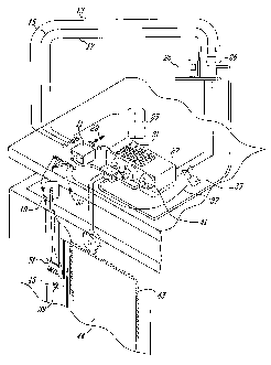
Brief description of the drawings
[0012] Figure 1 is a schematic diagram showing perspective view of an
embodiment of the invention; and
[0013] Figure 2 is a block diagram of another embodiment of the
invention.
Detailed description of the invention
[0014] In a cold room, there are different ways to control and/or monitor
the temperature either with mechanical devices or with electronic controls.
Door frames in a cold room often requires an anti-sweating heating element to
eliminate condensation in the door perimeter and it could be of a variable
CA 02419647 2003-02-21
-4-
power for energy saving. There are also devices available on the market to
manage safety and energy saving features. With the latest technologies on
the market, using electronics, there are at least 4 different devices required
to
achieve those functions;
1. An electronic refrigeration controller to control precisely the
temperature in the cold room and manage the defrost cycles
2. An alarm system to monitor and provide alarm if low or high
temperature are reached
3. A thermostat or a dimmer to control the power level of the anti-
sweating heater
4. An energy saving device to manage automatically the lighting inside
the cold room triggered by the opening of the door. It manages the
interruption of the operation for the evaporator fans and the solenoid
valve when the door is opened or if people needs to work inside the
cold room. It also provides door open alarm as well as panic alarm.
[0015] It uses a software based electronic controller with internal memory
and RTC (real time clock) for data logging and different inputs/outputs as
well
as interfaces to communicate with peripheral as modems and computers. It
includes a power failure back-up either by using battery or capacitor to
maintain the vital functions of the system as monitoring, data logging and
alarm signal during the power failures. The inputs/outputs and peripheral are
as follow:
1. A temperature probe to read air temperature inside the cold room to
allow monitoring, alarm and data logging. It also triggers the operation
of the anti-sweat heater which is not required at higher temperature.
2. A temperature probe to read food temperature inside the cold room to
allow monitoring, alarm and data logging.
3. A temperature probe to read evaporator coil temperature to control
defrost cycles.
4. A temperature probe to read condenser or compressor temperature for
equipment safety and trouble shooting purpose.
CA 02419647 2003-02-21
-5-
5. A suction pressure probe at the inlet of the compressor for equipment
safety and trouble shooting purpose.
6. A compressor pressure probe at the outlet of the compressor for
equipment safety and trouble shooting purpose.
7. A backlit push button to be installed inside the cold room, beside the
door opening and recessed flush into the door frame, with all the wiring
embedded in the insulation and leading out of the cold room for
sanitary purpose. This button controls the lighting in different modes,
to shut temporarily the evaporator fans and/or to activate a panic
alarm.
8. A door detector, beside the door opening and recessed flush into the
door frame, with all the wiring embedded in the insulation and leading
out of the cold room for sanitary purpose. The detector triggers the
automatic lighting control and/or the interruption of the evaporator fan &
solenoid while the door is left opened.
9. A keyboard to be installed outside the cold room, beside the door
opening and recessed flush into the door frame, with all the wiring
embedded in the insulation and leading out of the cold room for
sanitary purpose. The keyboard includes push buttons (or keys) with
multi-functions, data display readout and status indicators. The push
buttons allow control of different parameters manually such as lighting
control, select data to be displayed on the readout, acknowledge or
reset alarm and access the menu mode that allow to configure the
system and set the variables as timers, set points, alarm levels and
operation modes. The menu also allows viewing the data logged into
the memory. The display allows viewing temperature, pressure,
internal registers value accessed by the menu, logged data, and short
messages. The status indicators show the status of different
parameters of the systems, indicates modes of operation and alarm
status.
10. An output to control the lighting inside the cold room based on the
sequence programmed in the controller and the status of the inputs.
CA 02419647 2003-02-21
-6-
11. An output to control the evaporator fan based on the sequence
programmed in the controller and the status of the inputs.
12. An output to control either the liquid solenoid valve or the compressor
itself based on the sequence programmed in the controller and the
status of the inputs.
13. An audible alarm signal wired to either a buzzer, a horn or both.
14. An output to control the defrost elements in the evaporator based on
the sequence programmed in the controller and the status of the
inputs.
15. An output to control the anti-sweat heater wire to the proper level of
power based on the environmental requirement. This allows energy
saving with less heating requirement and prevents excess heating from
being compensated by the refrigeration system.
[0016] With the different inputs, outputs and data communication
capability all linked together on the controller, it open for a tremendous
amount of features and functionality that will increase the efficiency of the
overall operation in terms of accuracy, energy saving, safety, maintenance
and traceability. Using a single controller will lead in a cost saving as
opposed to independent controlling and monitoring devices. The following are
some features and functionalities that can be performed by the system. From
the architecture of the system, additional features and functionality may be
added simply by revising the software in the electronic controller.
1. Depending on the end-user preference, lighting could work in three
different modes (user defined in the configuration menu). In manual
mode the user presses a keyboard light key or inside button
momentarily to turn light on or off. In semi-auto mode, the light is
turned on or off by the keyboard or the inside button and it is
automatically turned off when the door is closed, after a user defined
delay (by the menu mode). Holding the keyboard or inside button for
1.5 seconds will prevent the lighting from being turned off
automatically. The auto mode allows turning on the light simply by
CA 02419647 2003-02-21
7 _
opening the door of the cold room, all the semi-auto features also
apply. A status indicator shows the mode of operation and another
status indicator shows if the light is either on, off or in a count down
cycle (blinking). In a large operation where the lighting shall stay on all
day, a fourth mode would allow to control the lighting based on the time
of the day. As an example, the lights would be automatically turned on
at 7:00 am and turned off at 6:00 pm. In this mode, the lighting could
still be controlled manually by the on/off buttons. In order to prevent the
light to shut off while there is somebody inside, the buzzer would warn
for few minutes before shutting off.
2. The anti-sweat heater wire is controlled by the electronic unit and
activated if temperature is lower than a user defined temperature. In
order to apply the proper amount of heating, the output is cycled on
and off in time, for example, at 50% the output is on half of the time.
Both activation temperature and power level are configurable by the
menu mode.
3. There are 4 types of alarms generated by the system; high or low
temperature alarm, door open alarm, panic alarm and refrigeration
system malfunction or failure alarm. Using the menu mode, each of
the alarm can be enabled or disabled and each one can be configured
to send or not an outside signal through a dry contact. When an alarm
occurs, the appropriate status indicator flashes on the keyboard and a
local buzzer is activated according to the type of alarm (1 beep to 4
beeps sequence). The buzzer can be silenced temporarily by pressing
an acknowledge button on the keyboard, the status light will still blink
and the outside signal will remain energized if selected. If the alarm is
still active after a user defined delay, the buzzer will be reactivated. It
can be permanently silenced by pressing twice the acknowledge button
on the keyboard.
The Hi/Lo temperature alarm level and the delay before activation are
defined in the menu mode by the user.
CA 02419647 2003-02-21
_ $ _
The door open alarm is activated when the door is left open after a
user defined delay. In order to avoid false alarm to the outside signal
during normal operation, the outside signal, if selected, will be activated
only after 3 times the preset delay that initiate the alarm.
The panic alarm can only be activated when the door is closed, by
holding the inside button for a couple of seconds. Since the lighting
control is also triggered by the inside button, the sequence will be that
the light will turn on permanently if not already and then the panic
alarm will be activated. The alarm is cancelled by opening the door or
by pressing the acknowledge key on the keyboard.
The refrigeration system alarm is detected by the two pressure probes
and the two temperature probes located in the evaporator coil and on
compressor/condenser temperature probe. Monitoring those
parameters will allow to detect gas leak, dirty condenser or ice build-up
in the evaporator coil.
4. The refrigeration system is completely managed by the electronic
controller and includes temperature regulation, defrost cycles and
evaporator fan interruptions. The temperature regulation is achieved
by measuring the air temperature inside the cold room (or the product
temperature probe) and, based on the user defined set point and
hysterisis, controlled by either the solenoid valve or the compressor.
The number of defrost cycles and their duration are user defined and
the controller will manage the solenoid valve, the fans and the defrost
elements based on the evaporator coil temperature or maximum
defrost time defined by the user. Through the keyboard, a manual
defrost could also be initiated.
The evaporator fan interruption that is required when the door is
opened (triggered by the door switch) or when a user is working inside
the cooler (triggered by the keyboard) is managed considering the
inside temperature as a priority. This means that if because of the fan
and solenoid valves are turned off, the temperature rises at or over the
high temperature alarm level, the fan and solenoid will resume into
CA 02419647 2003-02-21
_g_
normal operation to lower the temperature in the cold room back to its
temperature set point. If the door is left opened for longer than the
door open alarm delay, the fan and solenoid valve will also resume into
normal operation.
The system also features an option that manages the initial start-up of
the refrigeration system. In order to prevent ice build-up in the
evaporator coil that some times occurs in the first cool down, the
system lowers the temperature in incremental temperature steps and
will initiate a defrost cycle in between each steps until the final
temperature is reached. This option will be selected by the menu
mode and the range of the step will be user defined.
5. The electronic system includes a data memory as well as a Real Time
Clock (RTC) allowing data logging of different parameters of the
system related to the date and time. The configuration and the
information recorded are accessible through the menu mode. The
system logs any alarm status combined with time, period and value of
the parameter being in fault. The system is also configured to log, at
given time intervals, some variables of the system such as inside cold
room temperature, product temperature, evaporator coil temperature,
compressor/condenser temperature, suction pressure and compressor
pressure. The system also has the capability to log for a time interval
(ex. In 24 hours), different status of the system as running time of the
compressor, running time of the fans, running time for the defrost cycle,
door open time and "light on" time. The system logs the highest and
the lowest value reached of all analog inputs. The system is
programmed to also log any combination of the status or value from the
inputs and outputs of the system.
6. The system features one or few data ports that will allow
communication with other peripheral as computer, modem or any other
communication device. The link could be either by cable or infrared
port. The communication ports allows downloading logged data to a
computer, sending alarm signals on line, allowing remote monitoring of
CA 02419647 2003-02-21
-10-
any parameters of the system and allowing controlling the system or
modifying its parameters remotely. The data port also allows to link
similar system into a network (require a second data port). The
program, the configuration, any upgrade or revisions of the system
could also be loaded by the communication port.