Note : Les descriptions sont présentées dans la langue officielle dans laquelle elles ont été soumises.
CA 02420417 2008-10-24
TITLE OF THE INVENTION
COLOR-STABILIZED ELECTROCHROMIC DEVICES
BACKGROUND OF THE INVENTION
1. Field of the Invention
The present invention relates in general to electrochromic devices, and more
particularly, to normally operating, color-stabilized electrochromic devices
having an
electrochromic medium comprising one or more redox buffers,'which serve to
substantially preclude the formation of undesirable residual color within the
electrochromic medium while in its high transmission state.
2. Background Art
Electrochromic devices have been known in the art for several years. While the
utilization of electrochromic devices, such as electrochromic mirrors, has
become
increasingly popular among, for example, the automotive industry, the
development of
undesirable residual color within the electrochroniic medium of such
electrochromic
devices remains problematic.
Indeed, when a sufficient electrical potential difference is applied across
the
electrodes of a conventional electrochromic device, the electrochromic medium
becomes
intentionally colored (i.e. a low transmission state) inasmuch as one or more
of the anodic
and the cathodic materials are oxidized and reduced, respectively.
Specifically, the
anodic materials are oxidized by donating one or more electron(s) to the anode
and the
CA 02420417 2003-02-24
WO 02/19022 PCT/US01/26888
cathodic materials are reduced by accepting one or more electron(s) from the
cathode.
For most commercially available electrochromic devices, when the electrical
potential difference is removed or substantially diminished, the anodic and/or
cathodic
materials return to their zero-potential or unactivated state, and in turn,
return the
electrochromic medium to a predetermined state, which is conventionally
colorless,
nearly colorless, or intentionally tinted (i.e. a high transmission state).
The application
and removal of an electrical potential difference is conventionally known as a
single cycle
of the electrochromic device.
Scientists have observed that over a period of cycles and/or time, during
normal
operation of the electrochromic device, the electrochromic medium sometimes
does not
acceptably return to a predetermined state. In some instances, even in the
absence of an
electrical potential difference, a portion of the anodic and cathodic
materials may be
oxidized or reduced respectively, thereby forming residual color from the
oxidized and/or
reduced materials. The residual oxidized anodic materials or the residual
reduced
cathodic materials of the electrochromic mediuin can result in an undesired
residual
coloration of the electrochromic medium.
Factors that are believed to facilitate the formation of the undesired
residual
oxidized anodic and/or reduced cathodic materials include, among other things,
thermal
and/or photochemical decomposition of one or more of the medium materials,
and/or the
permeation of water and/or oxygen into the electrochromic medium.
2
CA 02420417 2003-02-24
WO 02/19022 PCT/US01/26888
It is therefore an object of the present invention to provide an
electrochromic
medium with one or more redox buffers which remedy the aforementioned
detriments
and/or complications associated with controllably maintaining a predetermined
color of
an electrochromic medium (i.e. colorless, nearly colorless, or intentionally
tinted) while
in a high transmission state relative to an electrochromic medium without the
redox
buffer.
SUMMARY OF THE INVENTION
The present invention is directed to the use of one or more redox buffers in
an
electrochroinic medium. To act as a redox buffer, a material will exhibit an
electrocheinical reaction within a range bounded by the first oxidation
potential of the
principal anodic material, typically the anodic electrochromic material, and
the first
reduction potential of the principal cathodic material, typically the cathodic
electrochromic material. The material may exhibit the electrochemical reaction
initially,
or alternatively may generate a species that exhibits the electrochemical
reaction after a
chemical reaction that follows oxidation or reduction. In this case, the redox
potential
corresponding to the oxidation or reduction process may lie outside of the
above-
identified range.
The present invention is also directed to an electrochromic device comprising:
(a)
at least one substantially transparent substrate having an electrically
conductive material
associated therewith; and (b) an electrochromic medium having a predetermined
color
while in a high transmission state, wherein the electrochromic medium
comprises: (1) an
anodic material and a cathodic material, wherein both of the anodic and
cathodic
3
CA 02420417 2003-02-24
WO 02/19022 PCT/US01/26888
materials are electroactive and at least one of the anodic and cathodic
materials is
electrochromic; (2) a redox buffer; and (3) means associated with the redox
buffer for
controllably maintaining the predetermined color of the electrochromic medium
while in
the high transmission state relative to an electrochromic medium without the
redox
51 buffer.
BRIEF DESCRIPTION OF THE DRAWINGS
The invention will now be described with reference to the drawings wherein:
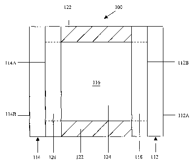
Fig. 1 of the drawings is a cross-sectional schematic representation of an
electrochromic device fabricated in accordance with the present invention;
Fig. 2 of the drawings is a two-dimensional plot showing color change as a
function of exposure time at 85 degrees centigrade for media lA and 1B of
Experiment
No. 1;
Fig. 3 of the drawings is a two-dimensional plot showing color change as a
function of exposure time at 85 degrees centigrade for media 2A and 2B of
Experiment
No. 2;
Fig. 4 of the drawings is a two-dimensional plot showing color change as a
function of exposure time at 85 degrees centigrade for media 3A and 3B of
Experiment
No. 3; and
Fig. 5 of the drawings is a two-dimensional plot showing color change as a
function of exposure time to cycling at 70 degrees centigrade for media 3A and
3B of
Experiment No. 3.
4
CA 02420417 2008-10-24
DETAILED DESCRIPTION OF THE INVENTION
Referring now to the drawings and to Fig. I in particular, a cross-sectional
schematic representation of electrochromic device 100 is shown, which
generally
comprises first substrate 112 having a front surface 112A and a rear surface
112B, second
substrate 114 having a front surface 114A and a rear surface 114B, and chamber
116 for
containing electrochromic medium 124. It will be understood that
electrochromic device
100 may comprise, for illustrative purposes only, a mirror, a window, a
display device, a
contrast enhancement filter, and the like. It will be further understood that
Fig. 1 is
merely a schematic representation of electrochromic device 100. As such, some
of the
components have been distorted from their actual scale for pictorial clarity.
Indeed,
numerous other electrochromic device configurations are contemplated for use,
including
those disclosed in U.S. Patent No. 5,818,625 entitled "Electrochromic Rearview
Mirror
Incorporating A Third Surface Metal Reflector" and U.S.
Patent No. 6,597,489 entitled "Electrode Design For Electrochromic Devices".
First substrate 112 may be fabricated from any one of a number of materials
that
are transparent or substantially transparent in the visible region of the
electromagnetic
spectrum, such as, for example, borosilicate glass, soda lime glass, float
glass, natural and
synthetic polymeric resins, plastics, and/or composites including Topas ,
which is
commercially available from Ticona of Summit, New Jersey. First substrate 112
is
preferably fabricated from a sheet of glass having a thickness ranging from
approximately
0.5 millimeters (mm) to approximately 12.7 nun. Of course, the thickness of
the
5
CA 02420417 2003-02-24
WO 02/19022 PCT/US01/26888
substrate will depend largely upon the particular application of the
electrochromic device.
While particular substrate materials have been disclosed, for illustrative
purposes only, it
will be understood that numerous other substrate materials are likewise
contemplated for
use - so lpng as the materials are at least substantially transparent and
exhibit appropriate
physical properties, such as strength to be able to operate effectively in
conditions of
intended use. Indeed, electrochromic devices in accordance with the present
invention can
be, during normal operation, exposed to extreme temperatures as well as
substantial UV
radiation, emanating primarily from the sun.
Second substrate 114 can be fabricated from similar materials as that of first
substrate 112. However, if the electrochromic device is a mirror, then the
requisite of
substantial transparency is not necessary. As such, second substrate 114 may,
alternatively, comprise polymers, metals, glass, and ceramics - to name a few.
Second
substrate 114 is preferably fabricated from a sheet of glass having a
thickness ranging
from approximately 0.5 mm to approximately 12.7 min. If first and second
substrates
112 and 114, respectively, are fabricated from sheets of glass, then the glass
can
optionally be tempered prior to or subsequent to being coated with layers of
electrically
conductive material (118 and 120).
One or more layers of electrically conductive material 118 are associated with
rear
surface 112B of first substrate 112. These layers serve as an electrode for
the
electrochromic device. Electrically conductive material 118 is desirably a
material that:
(a) is substantially transparent in the visible region of the electromagnetic
spectrum; (b)
bonds reasonably well to first substrate 112; (c) maintains this bond when
associated with
6
CA 02420417 2003-02-24
WO 02/19022 PCT/US01/26888
a sealing member; (d) is generally resistant to corrosion from materials
contained within
the electrochromic device or the atmosphere; and (e) exhibits minimal
diffusion or
specular reflectance as well as sufficient electrical conductance. It is
contemplated that
electrically conductive material 118 may be fabricated from fluorine doped tin
oxide
(FTO), for example TEC glass, which is commercially available from Libbey
Owens-
Ford-Co., of Toledo, Ohio, indium-doped tin oxide (ITO), doped zinc oxide or
other
materials known in the art.
Electrically conductive material 120 is preferably associated with front
surface
1 14A of second substrate 114, and is operatively bonded to electrically
conductive
material 118 by sealing member 122. As can be seen in Fig. 1, once bonded,
sealing
member 122 and the juxtaposed portions of electrically conductive materials
118 and 120
serve to define an inner peripheral geometry of chamber 116.
Electronically conductive material 120 may vary depending upon the intended
use
of the electrochromic device. For example, if the electrochromic device is a
mirror, then
the material may comprise a transparent conductive coating similar to
electronically
conductive material 118 (in which case a reflector is associated with rear
surface 114B of
second substrate 114). Alternatively, electrically conductive material 120 may
comprise a
layer of reflective material in accordance with the teachings of U.S. Patent
No.
5,818,625. In this case, electrically conductive material 120 is associated
with front
surface 114A of second substrate 114. Typical coatings for this type of
reflector include
chromium, rhodium, ruthenium, silver, silver alloys, and combinations thereof.
7
CA 02420417 2008-10-24
Sealing member 122 may comprise any material that is capable of being
adhesively bonded to the electronically conductive materials 118 and 120 to,
in tuxn, seal
chamber 116 so that electrochromic medium 124 does not inadvertently leak out
of the
chamber. As is shown in dashed lines in Fig. 1, it is also contemplated that
the sealing
member extend all the way to rear surface 1 12B and front surface 114A of
their
respective substrates. In such an embodiment, the layers of electrically
conductive
material 118 and 120 may be partially removed where the sealing member 122 is
positioned. If electrically conductive materials 118 and 120 are not
associated with their
respective substrates, then sealing member 122 preferably bonds well to glass.
It will be
understood that sealing member 122 can be fabricated from any one of a number
of
materials including, for example, those disclosed in U.S. Patent Nos.:
4,297,401;
4,418,102; 4,695,490; 5,596,023; 5,596,024; 4,297,401; and U.S. Patent
No. 6,157,480 entitled "Improved Seal For Electrochromic Devices".
For purposes of the present disclosure, electrochromic medium 124 includes,
among other materials, electroactive anodic and cathodic materials that upon
activation,
due to the application of an electronic voltage or potential, exhibit a change
in absorbance
at one or more wavelengths of the electromagnetic spectrum. The medium is
preferably
chosen from the following categories:
(i) Single layer-single phase:
The electrochromic medium may comprise a single layer of material which may
include small nonhomogenius regions and includes solution phase devices where
a
8
CA 02420417 2008-10-24
material contained in solution in the ionically conducting electrolyte which
remains in solution
in the electrolyte when electrochemically oxidized or reduced. Solution phase
electroactive
materials may be contained in the continuous solution phase of a free standing
rigid matrix in
accordance with the teachings of U.S. Patent No. 5,928,572 entitled "Improved
Electrochromic
Layer And Devices Comprising Same" and International Patent Publication No.
WO/1998/042796 entitled "Electrochromic Polymeric Solid Films, Manufacturing
Electrochromic Devices Using Such Solid Films, And Processes For Making Such
Solid Films
And Devices".
More than one anodic and cathodic material can be combined to give a pre-
selected
color as described in U.S. Patent No. 6,020,987 entitled "Improved
Electrochromic Medium
Capable of Producing A Pre-Selected Color".
The anodic and cathodic materials can be combined or linked by a bridging unit
as
described in International Publication No. W097/30134 entitled "Electrochromic
System".
It is also possible to link anodic materials or cathodic materials by similar
methods. The
concepts described in these applications can further be combined to yield a
variety of
electroactive materials that are linked, including linking of a redox buffer
to an anodic and/or
cathodic material.
Additionally a single layer-single phase medium may include a medium where the
anodic and cathodic materials are incorporated into a polymer matrix as is
described in
9
CA 02420417 2008-10-24
ti
International Publication No. W099/02621 entitled "Electrochromic Polymer
System" and International Patent Publication No. WO/1998/042796
"Electrochromic Polymeric Solid Films, Manufacturing Electrochromic Devices
Using
Such Solid Films, And Processes For Making Such Solid Films And Devices".
(ii) Multilayer - the medium may be made up in layers and includes a material
attached directly to an electronically conducting electrode or confined in
close proximity
thereto which remains attached or confined when electrochemically oxidized or
reduced.
Examples of this type of electrochromic medium include a W03/ionically
conducting
layer/counter layer electrochromic medium. An organic or organometallic layer
attached
to the electrode may also be included in this type.
(iii) Multiphase - one or more materials in the medium undergoes a change in
phase during the operation of the device, for example a material contained in
solution in
the ionically conducting electrolyte forms a layer on the electronically
conducting
electrode when electrochemically oxidized or reduced.
The cathodic material may include, for example, viologens, such as methyl
viologen tetrafluoroborate or octyl viologen tetrafluoroborate (El ln -300 mV
vs. the
E l I/2 peak of 5,10-dihydro-5,10-dimethylphenazine (hereinafter "DMP") at
+300 mV),
1,1',3,3'-tetramethyl-4,4'-bipyridinium tetrafluoroborate (E11/2 -700 mV vs.
DMP). It will
be understood that the preparation and/or commercial availability for each of
the above-
identified cathodic materials is well known in the art. While specific
cathodic materials
have been provided, for illustrative purposes only, numerous other
conventional cathodic
materials are likewise contemplated for use including, but by no means limited
to, those
CA 02420417 2008-10-24
disclosed in U.S. Patent No. 4,902,108.
Indeed, the only contemplated limitation relative to the cathodic material is
that it should not adversely affect the electrochromic performance of the
device 100.
Moreover, it is contemplated that the cathodic material may comprise a solid
transition
metal oxide, including, but not limited to, tungsten oxide.
The anodic material may comprise any one of a number of materials including
ferrocene (E11/2 +524 mV vs. DMP), substituted ferrocenes, substituted
ferrocenyl salts,
substituted phenazines, phenothiazine (El l/z +700 mV vs. DMP), substituted
phenothiazines, thianthrene, substituted thianthrenes. Examples of anodic
materials may
include di-tert-butyl-diethylfen:ocene, (6-(tetra-tert-
butylferrocenyl)hexyl)triethylammonium tetrafluoroborate (E11/2 +260 mV vs.
DMP), (3-
(tetra-tert-butylferrocenyl)propyl)triethylammonium tetrafluoroborate (El 1/2
+372 mV vs.
DMP), DMP (El in +300 mV as the reference), 3,7,10-trimethylphenothiazine,
2,3,7,8-
tetramethoxythianthrene (E1 1/2 + 748 vs. DMP), and 10-methylphenothiazine (EI
ln +880
mV vs. DMP). It will be understood that numerous other anodic materials are
contemplated for use including those disclosed in the previously referenced
'108 patent as well as U.S. Patent No. 6,188,505 entitled "Color-
Stabilized Electrochromic Devices" .
For illustrative purposes only, the concentration of the anodic and cathodic
materials can range from approximately I mM to approximately 500 mM and more
preferably from approximately 5 mM to approximately 50 mM. While particular
11
CA 02420417 2003-02-24
WO 02/19022 PCT/US01/26888
concentrations of the anodic as well as cathodic materials have been provided,
it will be
understood that the desired concentration may vary greatly depending upon the
geometric
configuration of the chamber containing electrochromic medium 124.
For purposes of the present disclosure, the solvent of electrochromic medium
124
may comprise any one of a number of cominon, commercially available solvents
including 3-methylsulfolane, glutaronitrile, dimethyl sulfoxide, dimethyl
formamide,
acetonitrile, tetraglyme and other polyethers, alcohols such as ethoxyethanol,
nitriles,
such as 3-hydroxypropionitrile, 2-methylglutaronitrile, ketones including 2-
acetylbutyrolactone, cyclopentanone, cyclic esters including beta-
propiolactone, gamma-
butyrolactone, gamma-valerolactone, propylene carbonate, ethylene carbonate
and
homogenous mixtures of the same. While specific solvents have been disclosed
as being
associated with the electrochromic medium, numerous other solvents that would
be
known to those having ordinary skill in the art having the present disclosure
before them
are likewise contemplated for use.
20
12
CA 02420417 2003-02-24
WO 02/19022 PCT/US01/26888
In accordance with the present invention, one or more redox buffers are
associated
with electrochromic medium 124, which controllably maintain the predetermined
color of
the electrochromic medium while in the high transmission state relative to an
electrocllromic medium witliout the redox buffer. The term "high transmission
state" is
defined as the bleached state, the zero-potential state, or the unactivated
state of the
electrochromic device.
In a first embodiment of the present invention, the redox buffer may comprise
one
or more materials represented by formulae I-A and/or I-B:
x,
3 5 R3 R1
I I Ra R2 XZ
:iiix11c
(I-A) X4 P-6 X2
(I-B)
wherein Xl-X4 are the same or different and comprise 0, C(CN)2, S, N(R7), or
N+(R7)(R8);
wherein Rl-R8 are the same or different and comprise H, a halide, a hydroxy
group, a
cyano group, or a substituted or unsubstituted alkyl, aryl, alkaryl, aralkyl,
or alkoxy group
containing approximately 1 to approximately 12 carbon atoms; and wherein Rl-
R2, R3-R4,
and/or R7-R8 may be associated with a substituted or unsubstituted benzo
group, a closed
ring, or form a partially saturated ring.
13
CA 02420417 2003-02-24
WO 02/19022 PCT/US01/26888
The redox buffer may also comprise one or more materials represented by
formulae II:
R4
R3 / X,
Rz \ X2
R1
(II)
wherein Xl-X2 are the same or different and comprise 0, C(CN)2, S, N(R7), or
N+(R7)(R8);
wherein Rl-R4 and R7-R8 are the same or different and comprise H, a halide, a
hydroxy
group, a cyano group, or a substituted or unsubstituted alkyl, aryl, alkaryl,
aralkyl, or
alkoxy group containing approximately 1 to approximately 12 carbon atoms; and
wherein
Rl-R2, R2-R3, R3-R4, and/or R7-R8 maybe associated with a substituted or
unsubstituted
benzo group, a closed ring.
More specifically, in this embodiment of the invention, the redox buffer may
comprise quinone, substituted quinones and/or mixtures of the same. For
example, the
redox buffer may be represented by at least one of the formulae:
0 cl O
::: Cl O Cl Cl
Cl Cl Cl
O (1) (2) Cl (3) 0 (4)
O O O O
CH3
I I I I 0
O (5) O (6) O O (7)
14
CA 02420417 2003-02-24
WO 02/19022 PCT/US01/26888
0 0 OH 0 OH 0
H3C CH3
/ \ / O O I I
(8)
0 (9) O (10)
0 OH 0 0 OH
~ ~ I I
0 ~
O OH (11) O OH 0 (12) (13)
0 0 0
CH2O(CHZ)ZCH3 H3C CH3
O O ~~ O O
H3C CH3
O (14) 0 (15) 0 (16).
CA 02420417 2003-02-24
WO 02/19022 PCT/US01/26888
Table 1 below provides redox potentials as well as CAS nuinbers for many of
above-identified redox buffers 1-16.
Table I
Redox Buffer E1 *(mV) CAS # Redox Buffer E1 *(mV) CAS #
1 +572 84-58-2 9 -400 117-10-2
2 +360 1518-16-7 10 -472 527-61-7
3 +284 2435-53-2 11 -472 81-64-1
4 +188 118-75-2 12 -480 N/A
-268 553-97-9 13 -528 117-12-4
6 -292 106-51-4 14 -592 N/A
7 -328 N/A 15 -640 527-17-3
8 -352 524-42-5 16 -712 84-65-1
* wherein El is the average of the anodic and cathodic peak potentials.
5 It will be understood that the above-identified quinones are merely
illustrative of
suitable quinones for use in accordance with the present invention, and that
numerous
other quinones which are compatible with the remainder of the electrochromic
device are
likewise contemplated for use.
In a second embodiment of the present invention, the redox buffer may comprise
a
material represented by forinula III-A:
R9
/
1'i Rio
Ril
(III-A)
16
CA 02420417 2003-02-24
WO 02/19022 PCT/US01/26888
wherein Yl comprises O+, N' (R1Z), or S+; wlierein Ry and Rl 1-R12 are the
same or different
and comprise H, a halide, a hydroxy group, a cyano group, a substituted or
unsubstituted
alkyl, aryl, alkaryl, aralkyl, or alkoxy group containing approximately 1 to
approximately
12 carbon atoms, or CF3; wherein Rlo comprises H, a halide, a hydroxy group, a
cyano
group, a substituted or unsubstituted alkyl, aryl, alkaryl, aralkyl, or alkoxy
group
containing approximately 1 to approximately 12 carbon atoms, CF3, or
Rt,
Z'2
R9
(III-B)
wherein Y2 coinprises O+, N'(R12), or S.
17
CA 02420417 2003-02-24
WO 02/19022 PCT/US01/26888
In this embodiment, the redox buffer may comprise pyrylium salt, substituted
pyrylium salts, bipyrylium salt, substituted bipyrylium salts, and mixtures
thereof. For
example, the redox buffer may be represented by at least one of the formulae:
0-61 / ~ 0 \ ~
[BFq]- [BF4]- I + _
(17) (18) / [BF4]
El 1/2 -592 mV vs. DMP
El 1/2 -212 mV vs. DMP (19)
CAS# 773-01-3
CAS# 448-61-3
[BF4]- +O/ \ [BF4] [BF4] +O/ + [BF4]-
C~~+
(20) (21).
It will be understood that the above-identified pyrylium salts are merely
illustrative of suitable pyrylium species for use in accordance with the
present invention,
and that numerous other pyrylium salts which are compatible with the remainder
of the
electrochromic device are likewise contemplated for use.
In a third embodiment, the redox buffer may comprise a material represented by
formula IV-A and/or IV-B:
X1M1 X3M3 R5 XIMI
R3 R1 R3 R1
4 R2
R¾ RZ
ZMZ X4M4 R6 X2M2 X
(IV-A) (IV-B)
18
CA 02420417 2003-02-24
WO 02/19022 PCT/US01/26888
wherein Xl-X4 are the same or different and comprise 0, C(CN)2, S, N(R7), or
N+(R7)(R.8);
wherein Rl-R8 are the same or different and comprise H, a halide, a hydroxy
group, a
cyano group, or a substituted or unsubstituted alkyl, aryl, alkaryl, aralkyl,
or alkoxy group
containing approximately 1 to approximately 12 carbon atoms; wherein Rl-R2, R3-
R4,
and/or R7-R8 may be associated with a substituted or unsubstituted benzo
group, a closed
ring, or form a partially saturated ring; and wherein M1-M4 are the same or
different and
comprise H+, Li+, Na+, K~, N+R4, %2Be2+, %zMg2+, %zCa2+, %2Srz+, etc.
The redox buffer may comprise one or more materials represented by formulae V:
R4
R3 \ X1Mi
I /
RZ XZMz
R1 (V)
wherein Xl-X2 are the same or different and comprise 0, C(CN)2, S, N(R7), or
N+(R7)(R$);
wherein Rl-R4 and R7-R8 are the same or different and comprise H, a halide, a
hydroxy
group, a cyano group, or a substituted or unsubstituted alkyl, aryl, alkaryl,
aralkyl, or
alkoxy group containing approximately 1 to approximately 12 carbon atoms;
wherein Rl-
RZ, R2-R3, R3-R4 and/or R7-R8 maybe associated with a substituted or
unsubstituted benzo
group, a closed ring, or form a partially saturated ring; and wherein Ml-M2
are the same
or different and comprise H+, Li+, Na+, K+, NR4+, %ZBe2+, '/zMg2+, %ZCa2+,
%Sr2+, etc.
19
CA 02420417 2003-02-24
WO 02/19022 PCT/US01/26888
More specifically, in this third embodiment the redox buffer may comprise
hydroquinone, substituted hydroquinones, and mixtures thereof. For example,
the redox
buffer may be represented by at least one of the fonnulae:
OH OH OH OH
CH3 H3C CH3
O O O
H3C O CH3
OH OH OH OH
(22) (23) (24) (25).
Table 2 below provides redox potentials as well as CAS numbers for many of
above-identified redox buffers 22-25.
Table 2
Redox Buffer EP* (mV) CAS # Redox Buffer EP * (mV) CAS #
22 N/A N/A 24 +1,064 88-58-4
23 +1,116 95-71-6 25 +984 N/A
* wherein EP is the anodic peak potential.
It will be understood that the above-identified hydroquinones are merely
illustrative of suitable hydroquinone species for use in accordance with the
present
invention, and that numerous other hydroquinones which are compatible with the
remainder of the electrochromic device are likewise contemplated for use.
CA 02420417 2003-02-24
WO 02/19022 PCT/US01/26888
In a fourth embodiment, the redox buffer may comprise a material represented
by
formula VI:
1 I
::ix::
(VI)
wherein Yl-YZ comprises O+, N(R12), or S; and wllerein Rl-R4 and R12 are the
same or
different and comprise H, a halide, a hydroxy group, a cyano group, a
substituted or
unsubstituted alkyl, aryl, alkaryl, aralkyl, or alkoxy group containing
approximately 1 to
approximately 12 carbon atoms, or CF3.
While specific redox buffers have been disclosed, for illustrative purposes
only,
numerous other redox buffers that would be known to those having ordinary
skill in the
art having the present disclosure before them are likewise contemplated for
use - so long
as the redox buffer controllably maintains the predetermined color of the
electrochromic
medium while in the high transmission state relative to an electrochromic
medium
without the redox buffer, and is otherwise compatible witli the remainder of
electrochromic device 100.
Preferably the concentration of the above-identified redox buffers range from
approximately 0.01 mM to approximately 10 mM.
In addition, electrochromic medium 124 may comprise other materials, such as
light absorbers, light stabilizers, thermal stabilizers, antioxidants, tint
providing agents,
and mixtures thereof. Suitable UV-stabilizers may include: the material ethyl-
2-cyano-
3,3-diphenyl acrylate, sold by BASF of Parsippany, NY under the trademark
Uvinul N-35
21
CA 02420417 2003-02-24
WO 02/19022 PCT/US01/26888
and by Aceto Corp., of Flushing, NY under the trademark Viosorb 910; the
material (2-
ethylliexyl)-2-cyano-3,3-diphenyl acrylate, sold by BASF under the trademark
Uvinul N-
539; the material 2-(2'-hydroxy-4'-methylphenyl)benzotriazole, sold by Ciba-
Geigy Corp.
under the trademark Tinuvin P; the material 3-[3-(2H-benzotriazole-2-yl)-5-
(l,1-
dimethylethyl)-4-hydroxyphenyl]propionic acid pentyl ester prepared from
Tinuvin 213,
sold by Ciba-Geigy Corp., via conventional hydrolysis followed by conventional
esterification (hereinafter "Tinuvin PE"); the materia12,4-
dihydroxybenzophenone sold
by, among many others, Aldrich Chemical Co.; the material 2-hydroxy-4-
methoxybezophenone sold by American Cyanamid under the trademark Cyasorb UV 9;
and the material 2-ethyl-2'-ethoxyalanilide sold by Sandoz Color & Chemicals
under the
trademark Sanduvor VSU - to name a few.
It will be understood that during normal operation, the electrochromic devices
of
the present invention are intended to be cycled between a high transmission
state and a
low transmission state numerous times while maintaining a predetermined
electrochromic
medium color (i.e. colorless, nearly colorless, or intentionally tinted)
during the high
transmission state relative to an electrochromic medium without the redox
buffer.
Electrochromic devices having as a component part a color-stabilized
electrochramic medium can be used in a wide variety of applications wherein
the
transmitted or reflected ligllt can be modulated. Such devices include rear-
view mirrors
for vehicles; windows for the exterior of a building, home or vehicle;
skylights for
buildings including tubular light filters; windows in office or room
partitions; display
devices; contrast enhancement filters for displays; light filters for
photographic devices
22
CA 02420417 2010-02-19
aild ilgiii selisors; and indicators Lor power ceil$ as well as primary and
seconQary
e:eeiroc heM::;a; :,c..s.
In support of the present invention, several experiinents were conducted
wherein
electrochromic devices were prepared which comprised one or more redox
buffer(s), the color-
~ St3bil12ed TJe?'t0T f71aJ7Ce of ,Ul?1Cl were GOITIpa_?'Zd t0 anaingqtic
~evlCes fabricated \V:tl,O it
a redo;: 'cuffer.
iii discussing colors 7t is useful to refer to the ConliillssioIl
l:nternutionale de
I'Eclairage's (ClE) 1976 CIELAB Chromaticity Diagram (coninlonly referred to
the
L*a*b ' cliart). The technology of color is relatively complex, but a fairly
comprehensive
discussion is given by F. W. Billmeyer and M. Saltzman in Principles of Color
~ ecllnology, 2"d Ed., J. Wiley and Sons Inc. (1981), and the present
disclosure, as it
relates to color techriology and terininology generally follows that
diseussion. On the
L*a*b* chart, L* defines lightness, a* denotes the red/green value and b*
denotes the
yellow/blue value. Each of the eleetrochromic media has an absorption spectra
at each
particular voltage that may be converted into a tluee number designation,
their L*a*b*
values. Color change is calculated by importing L*a*b* values into the
following
formula:
AE = SQRT((Lt*-I.*)z + (at*- ap )2 + (bt*- bo*)2)
-wherein AE is the color cha.nge;
SQRT is tlie square root operation;
Subscript "0" is an initial value (for L*,a*, or b*); and
Subscript "t" is a value after a given amount of time (foi- L*, a*, or b*).
23
CA 02420417 2003-02-24
WO 02/19022 PCT/US01/26888
Experiment No. 1
In Experiment No. 1, two different electrochromic media (lA and 1B) were
prepared by mixing the following materials together in the concentrations
provided below:
Medium 1 A
Component Material Concentration
Cathodic Oc lviolo en BF4 Z 38.0mM
Anodic 5,10-Dih dro-5,10-dimeth 1 henazine 27.0mM
Redox Buffer None -
UV-Stabilizer Tinuvin P 30.0mM
Thickener PMMA 3% b wt.
Solvent Propylene carbonate -
Medium 1 B
Component Material Concentration
Cathodic Oc lviolo en BF4 2 38.0mM
Anodic 5,10-Dih dxo-5,10-dimeth 1 henazine 27.0mM
Redox Buffer Tri hen 1 lium BF4 1.0mM
UV-Stabilizer Tinuvin P 30.0mM
Thickener PMMA 3% b wt.
Solvent Propylene carbonate -
Media 1A and 1B of Experiment No. 1 were associated with different
electrochromic mirrors for testing. Specifically a first substrate was coated
with
generally clear, conductive fluorine-doped tin oxide, and the second was
coated with
fluorine-doped tin oxide with a standard silver reflector on rear surface
(114B). The
substrates were spaced 137 microns apart for accommodating the medium. Each
one of the
mirrors containing media 1A and 1B was stored in an oven at 85 degrees
centigrade to
simulate prolonged exposure to a thermally extreme environment. For each of
media lA
and 1B, L*a*b* data were collected at predetermined intervals, which were then
converted into color change values, the results of which are provided in Fig.
2. As is
shown in Fig. 2, the medium with,the triphenylpyrylium redox buffer (Medium
1B) is
24
CA 02420417 2003-02-24
WO 02/19022 PCT/US01/26888
substantially more stable than the medium without such a redox buffer (Medium
1A). In
fact, medium lA experienced a substantial change in color as is evident by its
relatively
large slope as compared to the relatively flat slope of medium 1B. Therefore,
Experiment
No. 1 verifies that, indeed, the usage of the above-identified redox buffer
provides an
effective mechanism to minimize the adverse coloration effects associated with
prolonged
exposure to thermally extreme environments.
Experiment No. 2
In Experiment No. 2, two different electrochromic media (2A and 2B) were
prepared by mixing the following inaterials together in the concentrations
provided
below:
Medium 2A
Component Material Concentration
Cathodic Oc lviolo en BFa 2 38.0mM
Anodic 5,10-Dih dro-5,10-dimeth 1 henazine 27.0mM
Redox Buffer None -
IJV-Stabilizer Tinuvin P 30.0tnM
Thickener PMMA 3 % by wt.
Solvent Propylene carbonate -
Medium 2B
Component Material Concentration
Cathodic Oc lviolo en BF4 Z 38.0mM
Anodic 5,10-Dih dro-5,10-dimeth 1 henazine 27.0mM
Redox Buffer 1 ,2-Na htho uinone 1.0mM
UV-Stabilizer Tinuvin P 30.0mM
Thickener PMMA 3% b wt.
Solvent Propylene carbonate -
Media 2A and 2B of Experiment No. 2 were associated with different
electrochromic mirrors for testing. Specifically a first substrate was coated
with
generally clear, conductive fluorine-doped tin oxide, and the second was
coated with
fluorine-doped tin oxide with a standard silver reflector on rear surface
(114B). The
CA 02420417 2003-02-24
WO 02/19022 PCT/US01/26888
substrates were spaced 137 microns apart for accommodating the medium. Each
one of the
mirrors containing media 2A and 2B was stored in an oven at 85 degrees
centigrade to
simulate prolonged exposure to a thermally extreme environment. For each of
media 2A
and 2B, L*a*b* data were collected at predetermined intervals, which were then
converted into color change values, the results of which are provided in Fig.
3. As is
shown in Fig. 3, the medium with 1,2-naphthoquinone as the redox buffer
(Medium 2B)
is substantially more stable than the medium without such a redox buffer
(Medium 2A).
In fact, medium 2A experienced a substantial change in color as is evident by
its
relatively large slope as compared to the relatively flat slope of medium 2B.
Therefore,
Experiment No. 2 verifies that, indeed, the usage of the above-identified
redox buffer
provides an effective mechanism to minimize the adverse coloration effects
associated
with prolonged exposure to thermally extreme environments.
Experiment No. 3
In Experiment No. 3, two different electrochromic media (3A and 3B) were
prepared by mixing the following materials together in the concentrations
provided
below:
Medium 3A
Component Material Concentration
Cathodic Oc lviolo en BF4 2 38.0mM
Anodic 5,10-Dih dro-5,10-dimeth 1 henazine 27.0mM
First Redox Buffer None -
Second Redox Buffer None -
UV-Stabilizer Tinuvin P 30.0mM
Thickener PMMA 3% b wt.
Solvent Propylene carbonate -
26
CA 02420417 2003-02-24
WO 02/19022 PCT/US01/26888
Medium 3B
Component Material Concentration
Cathodic Oc lviolo en [BF4]2 38.0mM
Anodic 5,10-Dih dro-5,10-dimeth 1 henazine 27.0mM
First Redox Buffer 1 ,2-Na htho uinone 0.75mM
Second Redox Buffer Tetrameth lh dro uinone 0.75mM
UV-Stabilizer Tinuvin P 30.0mM
Thickener PMMA 3% b wt.
Solvent Propylene carbonate -
Media 3A and 3B of Experiment No. 3 were associated with two different sets of
electrochromic mirrors for testing. Specifically a first substrate was coated
with
generally clear, conductive fluorine-doped tin oxide, and the second was
coated with
fluorine-doped tin oxide with a standard silver reflector on rear surface
(114B). The
substrates were spaced 137 microns apart for accommodating the medium. The
first set
of mirrors containing media 3A and 3B was stored in an oven at 85 degrees
centigrade to
simulate prolonged exposure to a thermally extreme environment (Fig. 4). The
second
set of mirrors containing media 3A and 3B was cycled at 70 degrees centigrade
(Fig. 5).
For each of the two sets, L*a*b* data were collected at predetermined
intervals, which
were then converted into color change values, the results of which are
provided in Figs.
4-5. As is shown in Fig. 4, the medium with the redox buffers (Medium 3B) is
substantially more stable than the medium without the redox buffers (Medium
3A). In
fact, medium 3A experienced a substantial change in color as is evident by its
relatively
large slope as compared to the relatively flat slope of medium 3B. Similar
results can be
seen with the mirrors cycled at 70 degrees centigrade in Fig. 5. Therefore,
Experiment
No. 3 verifies that, indeed, the usage of the above-identified redox buffers
provide an
effective mechanism to minimize the adverse coloration effects associated with
prolonged
27
CA 02420417 2003-02-24
WO 02/19022 PCT/US01/26888
exposure to thermally extreme environments and/or device cycling.
As can be seen from the above-provided experiments, the incorporation of one
or
more of the disclosed redox buffers substantially improves the color stability
of an
electrochromic medium - even under relatively extreme elevated temperatures.
While the invention has been described in detail herein in accordance with
certain
preferred embodiments thereof, many modifications and changes therein may be
effected
by those skilled in the art. Accordingly, it is our intent to be limited only
by the scope of
the appending claims and not by way of details and instrumentalities
describing the
embodiments shown herein.
28