Sélection de la langue

Search

Sommaire du brevet 2420628 

Énoncé de désistement de responsabilité concernant l'information provenant de tiers

Une partie des informations de ce site Web a été fournie par des sources externes. Le gouvernement du Canada n'assume aucune responsabilité concernant la précision, l'actualité ou la fiabilité des informations fournies par les sources externes. Les utilisateurs qui désirent employer cette information devraient consulter directement la source des informations. Le contenu fourni par les sources externes n'est pas assujetti aux exigences sur les langues officielles, la protection des renseignements personnels et l'accessibilité.

Disponibilité de l'Abrégé et des Revendications

L'apparition de différences dans le texte et l'image des Revendications et de l'Abrégé dépend du moment auquel le document est publié. Les textes des Revendications et de l'Abrégé sont affichés :

  • lorsque la demande peut être examinée par le public;
  • lorsque le brevet est émis (délivrance).
(12) Demande de brevet: (11) CA 2420628
(54) Titre anglais: A DEVICE TO AUDIBLY EXPRESS IMPEDANCE MEASUREMENT
Statut: Réputée abandonnée et au-delà du délai pour le rétablissement - en attente de la réponse à l’avis de communication rejetée
Données bibliographiques
(51) Classification internationale des brevets (CIB):
  • G01R 27/16 (2006.01)
  • G01D 07/12 (2006.01)
(72) Inventeurs :
  • LAWRENCE, CLIFTON (Trinité-et-Tobago)
(73) Titulaires :
  • CLIFTON LAWRENCE
(71) Demandeurs :
  • CLIFTON LAWRENCE (Trinité-et-Tobago)
(74) Agent: BLAKE, CASSELS & GRAYDON LLP
(74) Co-agent:
(45) Délivré:
(86) Date de dépôt PCT: 2001-08-29
(87) Mise à la disponibilité du public: 2002-03-07
Requête d'examen: 2003-02-27
Licence disponible: S.O.
Cédé au domaine public: S.O.
(25) Langue des documents déposés: Anglais

Traité de coopération en matière de brevets (PCT): Oui
(86) Numéro de la demande PCT: PCT/TT2001/000001
(87) Numéro de publication internationale PCT: TT2001000001
(85) Entrée nationale: 2003-02-25

(30) Données de priorité de la demande:
Numéro de la demande Pays / territoire Date
TT/A/2000/00116 (Trinité-et-Tobago) 2000-08-30

Abrégés

Abrégé français

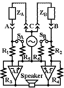
Cette invention a trait à un dispositif de comparaison d'impédance de contre-réaction audio exprimant de manière audible des différences existant entre des composants, des circuits, des matériaux, des substances, etc., faisant appel au sens de l'audition tout en soulageant la vue et diminuant l'effort cérébral et la fatigue de la nuque, ce dispositif ayant également pour objectif de réduire le temps d'investigation. On parvient à ce résultat en tenant compte de toutes les constituantes de l'utilisation de ladite sonde d'impédance, en l'occurrence, la coordination mains-oeil relative au positionnement de la sonde, la surveillance auditive de la contre-réaction, ces opérations remplaçant celles des pratiques/procédés habituels pour lesquels il est nécessaire de recentrer son regard sur des dispositifs visuels de contre-réaction. L'utilisation d'un signal alternatif permet d'effectuer une comparaison <= directe >= où plusieurs constituantes dont certaines ne réagissent pas à un signal statique, contribuent à l'établissement de l'impédance dans son ensemble. On peut utiliser ce dispositif pour injecter un signal audio dans un circuit actif et/ou pour en détecter la présence et/ou le suivre. On peut, en ayant recours à des transducteurs, utiliser ce dispositif avec d'autres formes d'énergie.


Abrégé anglais


An Audio Feedback Impedance Comparison Device to audibly express Impedance
differences between / amongst components, circuits, materials, substances
etc., to make use of the aural sense, while relieving eye, neck and mental
strain, as well as reduce probe time. This is achieved by allowing
simultaneous yet focused attention to be paid to all aspects of an impedance
probe, i.e. hand-eye coordination of probe positioning, while aurally
monitoring the feedback, instead of the common practices / methods where eyes
have to be re-focused on visual feedback devices. The use of an alternating
signal, allows "through" comparison, where multiple components some of which
are impervious to static signal, contribute to overall impedance. The device
can be used to inject and / or detect / trace the presence of an audio signal
in an active circuit. With the aid of transducers, this Device may be used
with other forms of energy.

Revendications

Note : Les revendications sont présentées dans la langue officielle dans laquelle elles ont été soumises.


7.
CLAIMS
What is claimed is:
1. A device that audibly expresses by magnitude of sound, the magnitude of the
Dynamic Impedance Difference between two or more
circuits/components/substances/
materials to various forms of energy such as
electricity/light/sound/vibration/motion using
the appropriate transducers in the comparison of various properties such as
electrical-/electronic-impedance/transparency/reflectivity/structural
soundness/mass/shape.
2. A device that audibly expresses by magnitude of sound, the magnitude of the
electrical Dynamic Impedance Difference between/among two or more electronic
components/ circuits.
3. A device that audibly expresses by magnitude of sound, the magnitude of the
electrical Dynamic Impedance Difference between/among two or more electrical
components/circuits.
4. A device that audibly expresses by magnitude of sound, the magnitude of the
Dynamic Impedance Difference to sound energy in between two or more physical
structures
through the use of sound and audio transducers, to compare distances or sound
conductive
substances/materials.
5. A device that audibly expresses by magnitude of sound, the magnitude of the
Dynamic Impedance Difference to vibration energy between two or more physical
structures
through the use of vibration and vibration transducers, to compare structural
soundness.
6. A device that audibly expresses by magnitude of sound, the magnitude of the
Dynamic Impedance Difference to vibration/motion energy between two or more
physical

-8-
structures through the use of vibration and motion transducers to compare
structural
soundness.
7. A device that audibly expresses by magnitude of sound, the magnitude of the
Dynamic Impedance Difference to light energy between two or more transparent
or reflective
masses through the use of light and light transducers, to compare transparency
and
reflectivity.
8. A device that audibly expresses by magnitude of sound, the magnitude of the
Dynamic Impedance Difference to various forms of energy of complex/compound
configurations by permitting 'through' comparison of varied and multiple
impedances in
conjunction, providing a more wholistic comparison of properties such as
electrical-
/electronic-impedance/transparency/reflectivity/structural
soundness/mass/shape.
9. A device that audibly expresses by magnitude of sound the magnitude of the
Dynamic Impedance Difference to various forms of energy of a
circuit/component/substance/material/structure under test, to a simulated
feedback of what is
expected.
10. A device that audibly expresses by magnitude of sound, the magnitude of
the
Dynamic Impedance Difference to various forms of energy of substance/material
structure
under test, to a recording of what it should actually be.
11. A device that with the use of transducers can in single unit mode by
either not
applying or by bypassing the energy on one channel, can audibly express
whether the
Dynamic Impedance of a circuit/substance/material/structure attached to the
other channel
completely impedes, or completely drains the energy applied, to ascertain that
the
circuit/substance/material/structure, indicates 'Open-Circuit' or 'Short-
Circuit' Conditions
respectively.

9.
12. A device that in single unit mode, by either not applying or by bypassing
the current
in one channel, can audibly express by magnitude whether the Dynamic Impedance
of a
circuit attached to the other channel completely impedes, or completely drains
the power
applied, to ascertain that the circuit, indicates an 'Open-Circuit' or 'Short-
Circuit' condition
respectively.
13. A device that with the use of an appropriate transducer in single unit
mode, by either
not applying or by bypassing the energy in one channel can audibly express by
magnitude of
sound whether the Dynamic Impedance of a substance under test on the other
channel
completely impedes or completely drains the energy applied, to ascertain that
the circuit,
indicates an 'Open-Circuit'/absence or 'Short-Circuit' presence condition
respectively.
14. A device that with the use of an appropriate transducer in single unit
mode, by either
not applying or by bypassing the energy in one channel, can audibly express by
magnitude
whether the Dynamic Impedance of a material under test on the other channel
completely
impedes, or completely drains the energy applied, to ascertain that the
circuit, indicates an
'Open-Circuit'/detachment or 'Short-Circuit'/attachment respectively.
15. A device that with the use of an appropriate transducer in single unit
mode, by either
not applying or by bypassing the energy in one channel, can audibly express by
magnitude
whether the Dynamic Impedance of a structure under test on the other channel
completely
impedes, or completely drains the energy applied, to ascertain that the
circuit, indicates an
'Open-Circuit'/isolated or 'Short-Circuit'/secured respectively.
16. A device that with little familiarity can produce intelligible by
magnitude, audible
feedback that can be used for basic checks on individual
circuits/components/substances/materials.

10.
I7. A device that with the use of appropriate transducers and without the
application of the
'AC', can be used to audibly express the presence of energy in an active
device or circuit.
18. A device that without the application of the 'AC' and with appropriate
amplification/attenuation, audibly expresses the presence of audio signal in
an active device or
circuit.
19. A device that with the use of a microphone and without the application of
the 'AC' and
with appropriate amplification/attenuation, audibly expresses the presence of
sound in a medium.
20. A device that with the use of a light transducer and without the
application of the 'AC'
and with appropriate amplification/attenuation, audibly expresses the audio
frequency
modulation of light.
21. A device that with the use of a vibration transducer and without the
application of the
'AC' and with appropriate amplification/attenuation, audibly expresses the
audio frequency
vibration of materials/substances.
22. A device that with the use of appropriate transducers, can be used to
audibly trace the
flow of energy from another source, through an active device or Circuit.
23. A device that with the use of appropriate transducers and the
reintroduction of the 'AC'
reference 'Ground', can be used in an active circuit to inject and trace the
process/processing of
the signal.
24. A device that with the reintroduction of the 'AC' reference 'Ground', can
be used in
an active electronic circuit to and trace the process/processing of an audio
frequency signal.

11.
25. A device that with the use of appropriate transducers and the
reintroduction of the 'AC'
reference 'Ground', can be used in an active circuit to inject and trace the
process/processing of
signals in multiple devices/circuits to match performances.
26. A device that with the use of appropriate transducers can be used to
audibly pre-match
components for assembly.

Description

Note : Les descriptions sont présentées dans la langue officielle dans laquelle elles ont été soumises.


CA 02420628 2003-02-25
WO 02/18957 PCT/TTO1/00001
DYNAMIC IMPEDANCE COMPARATOR
BACKGROUND OF THE INVENTION
This Invention is as a result of a quest to find a cheap, simple and effective
way to
troubleshoot malfunctions due to Impedance change, since component failure is
usually
reflected as such.
DESCRIPTION OF PRIOR ART
In Electronics, the current method of troubleshooting is generally to verify
that
individual components within a circuit retain their rated manufactured
properties. The various
properties usually require different methods and sometimes full or partial
removal/isolation,
to obtain accurate measurements. The Test Equipment most commonly used to
verify
component properties is the mufti-meter, and since most mufti-meters operate
with a D.C. test
Signal, they are unable to check Reactive Impedances. The main feedback from
Multi-
meters is visual, therefore using a Mufti-meter requires firstly, visual
attention in the
positioning of the probes, then, refocusing on a display to read a value.
Comparison between
two circuits requires either two mufti-meters, or checking and recording each
reading.
Testing is sometimes also done using a signal generator and oscilloscope. This
method,
though very effective, requires two pieces of equipment, still uses visual
feed back and is
relatively expensive. These current methods are not primarily geared for
comparison.
Comparisons are usually done as a choice of method by the investigator.
SUMMARY OF THE INVENTION
The Invention uses analog components in this digital era, to quickly isolate
faults
even in these modern digitised pieces of equipment.

CA 02420628 2003-02-25
WO 02/18957 PCT/TTO1/00001
2.
DESCRIPTION OF THE INVENTION
The Operation of the Dynamic Impedance Comparator is explained using the
following thirteen (13) diagrams.
Figure 1. An Audio Frequency Voltage Generator called 'AC', whose Output is
applied to
the points labeled'In', in Figure two (2,) through Figure six (6).
Figure 2. (The Fundamental Circuit). A Resistive Bridge where 'R1' equals
'R2', and 'RA'
and 'RB' are of unknown value. 'R1' and 'R2' also act as current limners in
the
Circuit. Any difference in the Resistances of 'RA' and 'RB', causes a Voltage
to
be present across the points labeled 'Out'. The Circuit can be said to consist
of
two halves. One consisting of 'RA' and 'R1', and the other consisting of 'RB'
and
'R2'.
NB. If any Measuring Device were to be connected across the terminals
labeled'Out',
the power drawn by this Device, would change the Voltage across these
terminals, hence the following configuration.
Figure 3. Operational Amplifiers (Op-Amps) 'Al' and 'A2', and Resistors 'R3'
and 'R4' with
resistances equal to 'R1' and 'R2', are now added to Figure 2. The Op-Amps are
configured as Unity-Gain Inverting Amplifiers, with the positive (+) inputs
grounded, and 'R1' and 'R2' used as the Inputs. The physically grounded points
of 'R1' and 'R2' in Figure 2., are now virtually grounded at the union of the
Negative (-) Tnput of 'Al' and 'R3', and the union of the Negative (-) Input
of 'A2'
and 'R4' respectively. The Output at the terminals labeled 'Out2' between the
union of 'R4' and the Output of Op-Amp 'A2', and the union of 'R3' and the
output of Op-Amp 'A1', is equal in phase and magnitude to output at the
terminals labeled 'Out2' between the union of 'RA' and 'R1', and the union of
'RB'
and 'R2' respectively.

CA 02420628 2003-02-25
WO 02/18957 PCT/TTO1/00001
3.
Figure 4. The Outputs of the Op-Amps labeled'Out2' in Figure 3. is now
connected to a
Sound Reproduction Device labeled'Speaker'. Any Difference in the Resistance
between'R1' and'R2' can now be "heard".
Figure 5. When Resistances 'RA' and 'RB' in Figure 3. are replaced with
Impedances 'ZA'
and'ZB', which may comprise of Resistive, Capacitive, Inductive or Semi-
Conductive properties of Electronic or Electrical Circuits or Components, or
reflections of the electrical properties such as resistance dielectricity,
magnetic
permeability of substances or materials, Impedance Differences are made
audible.
Figure 6. The addition of equal resistances 'R5' and 'R6' to Figure 5., allows
for increased
currents through the Impedances 'ZA' and 'ZB' respectively, without increasing
the currents through the Op-Amps, yet still producing a voltage across the
speaker, equal to that across the 'separate' terminals of 'ZA' and 'ZB'.
Figure 7. The Unknown Impedances 'ZA' and 'ZB' in Figure 6. have now been
separated
from the rest of the circuit. The Point of union (labeled 'In' in Figure 6) of
the
Unknown Impedances, and the free ends of the Unknown Impedances provide
three (3) terminals. Figure 1. is now integrated into the rest of the circuit
eliminating the need for Ground, which was being used as a reference to unite
Figure 1., to Figure 2. through Figure 6. 'R5' and 'R6' have been made
selectable
by adding Ganged Switch 'SA', 'SB'. The connector labeled 'C' (Common),
previously called 'AC', together with connectors labeled 'A' and 'B' at the
free
ends of 'R1' and 'R2' respectively also provide three (3) terminals. These are
the
Terminals of this (Basic Version) Test Device called the Dynamic Impedance
Comparator.

CA 02420628 2003-02-25
WO 02/18957 PCT/TTO1/00001
4..
NB. The ratio of the values of the Resistors 'Rl' to 'R4', though introduced
as
equal, along with the Values of 'R5 and R6', can be varied or even replaced
with
complex Impedances or an Impedance network to
1. accommodate proportional impedances, or
2. vary the gain of the amplifiers to increase or decrease sensitivity.
The Op-Amps may also be replaced with High Voltage/Power Frequency
Amplifiers 'Amps', functioning in the same manner, and retaining the labels
'A1'
and 'A2', for Industrial Applications. The 'Speaker' may also be isolated from
the
Circuit as necessary. This concept is only demonstrated using electricity and
electrical impedance. However, impedances to other forms of energy e.g. sound,
motion, light etc., can be monitored and compared by energy
conversions/adaptations some of which are stated below. When the Energy
produced by 'AC' is in the form of sound, motion, light etc., appropriate
transducers may be used to convert the energy flow, or reaction to this
energy, to
Sound.
Figures 8 through 13 illustrate modifications to accommodate various Unknown
Impedance and/or Configurations.
Figure 8. Connector 'C' is split to two terminals, to provide for comparison
of Separate
Impedances.
Figure 9. Resistors 'R1' through 'R6' have been replaced with Impedances 'Z1'
through 'Z6'
to enhance specific characteristic differences of Compound Impedances.
Figure 10. Impedances 'Z1', 'Z2', 'Z5' and 'Z6' have been removed from the
Circuit in Figure
9 and the Unknown Impedances are connected directly to a variation of the
Dynamic Impedance Comparator. This configuration makes the Unknown
Impedances the sole Current (inversely proportional to the Impedance)

CA 02420628 2003-02-25
WO 02/18957 PCT/TTO1/00001
5.
determining factors in each half of the circuit, which in turn, is responsible
for
the Voltage across the Speaker.
Figure 11. NB. Impedances 'Z3' and 'Z4' are removed for simplicity. In this
configuration,
Impedances 'Z1' and 'Z2' form the Inputs to the Inverting Amplifiers. This
configuration regulates the Currents to the Impedances 'ZA' and 'ZB' in
another
variation of the Dynamic Impedance Comparator. If 'Z1' and 'Z2' then the
Currents will be equal causing the Voltage (directly related to current)
across the
Speaker, to be based solely on the Tmpedance difference between 'ZA' and 'ZB'.
Figure 12. Due to the numerous possible configurations, the Circuit is
represented as an
Impedance Network where the Unknown Irnpedances, are attached as
components of the Network.
Figure 13. For checks on Single Impedances, comparison may be made with
Simulated or
Pre-Recorded Signals.
Summary of Modifications
Input Modifications include transducers to detect non electrical properties
such
as motion, light, sound, pressure.
AC Modifications include higher or lower power with variable, sweep, pulsed,
intermittent, customised, higher than audible frequencies etc. Pre-Recorded
'AC'
and Output Signal to be used as a reference for stand-alone checking.
Circuit modifications higher or lower power/frequency handling amplifiers with
customised Impedances.

CA 02420628 2003-02-25
WO 02/18957 PCT/TTO1/00001
6.
Output Modifications include the replacement of the Speaker with amplifiers;
attenuators, transducers, isolators, recorders, meters rectifiers,
oscilloscopes,
computers.
Configuration An inverting amplifier was only used to demonstrate the circuit,
however, non-inverting or other configurations may also be used.
15
25

Dessin représentatif
Une figure unique qui représente un dessin illustrant l'invention.
États administratifs

2024-08-01 : Dans le cadre de la transition vers les Brevets de nouvelle génération (BNG), la base de données sur les brevets canadiens (BDBC) contient désormais un Historique d'événement plus détaillé, qui reproduit le Journal des événements de notre nouvelle solution interne.

Veuillez noter que les événements débutant par « Inactive : » se réfèrent à des événements qui ne sont plus utilisés dans notre nouvelle solution interne.

Pour une meilleure compréhension de l'état de la demande ou brevet qui figure sur cette page, la rubrique Mise en garde , et les descriptions de Brevet , Historique d'événement , Taxes périodiques et Historique des paiements devraient être consultées.

Historique d'événement

Description Date
Lettre envoyée 2012-08-20
Inactive : Correspondance - Poursuite 2012-07-27
Demande non rétablie avant l'échéance 2011-08-29
Le délai pour l'annulation est expiré 2011-08-29
Inactive : Taxe finale reçue 2011-07-27
Requête en rétablissement reçue 2011-07-27
Préoctroi 2011-07-27
Retirer de l'acceptation 2011-07-27
Taxe finale payée et demande rétablie 2011-07-27
Réputée abandonnée - omission de répondre à un avis sur les taxes pour le maintien en état 2010-08-30
Réputée abandonnée - les conditions pour l'octroi - jugée non conforme 2010-07-27
Inactive : Lettre officielle 2010-01-29
Un avis d'acceptation est envoyé 2010-01-27
Lettre envoyée 2010-01-27
Un avis d'acceptation est envoyé 2010-01-27
Inactive : Approuvée aux fins d'acceptation (AFA) 2010-01-19
Modification reçue - modification volontaire 2008-10-02
Inactive : Dem. de l'examinateur par.30(2) Règles 2008-04-02
Modification reçue - modification volontaire 2007-06-15
Inactive : Correction à la modification 2007-06-05
Modification reçue - modification volontaire 2007-05-09
Inactive : Dem. de l'examinateur art.29 Règles 2006-11-09
Inactive : Dem. de l'examinateur par.30(2) Règles 2006-11-09
Lettre envoyée 2003-05-08
Inactive : Page couverture publiée 2003-04-28
Inactive : Inventeur supprimé 2003-04-24
Inactive : Notice - Entrée phase nat. - Pas de RE 2003-04-24
Demande reçue - PCT 2003-03-27
Requête d'examen reçue 2003-02-27
Exigences pour une requête d'examen - jugée conforme 2003-02-27
Toutes les exigences pour l'examen - jugée conforme 2003-02-27
Modification reçue - modification volontaire 2003-02-26
Exigences pour l'entrée dans la phase nationale - jugée conforme 2003-02-25
Demande publiée (accessible au public) 2002-03-07

Historique d'abandonnement

Date d'abandonnement Raison Date de rétablissement
2011-07-27
2010-08-30
2010-07-27

Taxes périodiques

Le dernier paiement a été reçu le 2009-08-28

Avis : Si le paiement en totalité n'a pas été reçu au plus tard à la date indiquée, une taxe supplémentaire peut être imposée, soit une des taxes suivantes :

  • taxe de rétablissement ;
  • taxe pour paiement en souffrance ; ou
  • taxe additionnelle pour le renversement d'une péremption réputée.

Les taxes sur les brevets sont ajustées au 1er janvier de chaque année. Les montants ci-dessus sont les montants actuels s'ils sont reçus au plus tard le 31 décembre de l'année en cours.
Veuillez vous référer à la page web des taxes sur les brevets de l'OPIC pour voir tous les montants actuels des taxes.

Historique des taxes

Type de taxes Anniversaire Échéance Date payée
Taxe nationale de base - générale 2003-02-25
TM (demande, 2e anniv.) - générale 02 2003-08-29 2003-02-25
Requête d'examen - générale 2003-02-27
TM (demande, 3e anniv.) - générale 03 2004-08-30 2004-08-27
TM (demande, 4e anniv.) - générale 04 2005-08-29 2005-08-29
TM (demande, 5e anniv.) - générale 05 2006-08-29 2006-08-24
TM (demande, 6e anniv.) - générale 06 2007-08-29 2007-08-29
TM (demande, 7e anniv.) - générale 07 2008-08-29 2008-08-29
TM (demande, 8e anniv.) - générale 08 2009-08-31 2009-08-28
Rétablissement 2011-07-27
Taxe finale - générale 2011-07-27
Titulaires au dossier

Les titulaires actuels et antérieures au dossier sont affichés en ordre alphabétique.

Titulaires actuels au dossier
CLIFTON LAWRENCE
Titulaires antérieures au dossier
S.O.
Les propriétaires antérieurs qui ne figurent pas dans la liste des « Propriétaires au dossier » apparaîtront dans d'autres documents au dossier.
Documents

Pour visionner les fichiers sélectionnés, entrer le code reCAPTCHA :


Pour visualiser une image, cliquer sur un lien dans la colonne description du document (Temporairement non-disponible). Pour télécharger l'image (les images), cliquer l'une ou plusieurs cases à cocher dans la première colonne et ensuite cliquer sur le bouton "Télécharger sélection en format PDF (archive Zip)" ou le bouton "Télécharger sélection (en un fichier PDF fusionné)".

Liste des documents de brevet publiés et non publiés sur la BDBC .

Si vous avez des difficultés à accéder au contenu, veuillez communiquer avec le Centre de services à la clientèle au 1-866-997-1936, ou envoyer un courriel au Centre de service à la clientèle de l'OPIC.

({010=Tous les documents, 020=Au moment du dépôt, 030=Au moment de la mise à la disponibilité du public, 040=À la délivrance, 050=Examen, 060=Correspondance reçue, 070=Divers, 080=Correspondance envoyée, 090=Paiement})


Description du
Document 
Date
(aaaa-mm-jj) 
Nombre de pages   Taille de l'image (Ko) 
Description 2003-02-24 6 220
Dessin représentatif 2003-02-24 1 11
Revendications 2003-02-24 5 183
Dessins 2003-02-24 13 133
Abrégé 2003-02-24 2 62
Description 2003-02-25 6 375
Revendications 2003-02-25 4 199
Revendications 2007-05-08 2 74
Description 2007-06-14 8 417
Revendications 2008-10-01 2 75
Dessin représentatif 2010-01-25 1 7
Accusé de réception de la requête d'examen 2003-05-07 1 174
Avis d'entree dans la phase nationale 2003-04-23 1 189
Avis du commissaire - Demande jugée acceptable 2010-01-26 1 163
Courtoisie - Lettre d'abandon (taxe de maintien en état) 2010-10-24 1 175
Courtoisie - Lettre d'abandon (AA) 2010-10-18 1 165
PCT 2003-02-24 6 193
PCT 2003-02-25 7 294
Taxes 2004-08-26 1 34
Taxes 2005-08-28 1 24
Taxes 2006-08-23 1 31
Taxes 2007-08-28 1 29
Taxes 2008-08-28 1 26
Taxes 2009-08-27 1 201
Correspondance 2010-01-26 1 31
Correspondance 2011-07-26 5 165
Correspondance 2012-08-19 1 16