Note : Les descriptions sont présentées dans la langue officielle dans laquelle elles ont été soumises.
CA 02422039 2006-06-12
1
ARRANGEMENT AT A PISTON ENGINE AND METHOD OF CONTROLLING THE
PISTONS
The invention regards an arrangement at a piston engine in
the form of a piston pump/engine of the type in which two or
s more co-operating piston cylinders, the reciprocating pistons
of which have piston rods that at any time will project more
or less outside the respective cylinders and be influenced by
a rotatable body for control of each piston, to impart to
this a predetermined displacement in the respective cylinder,
io which displacement is matched to the corresponding
displacement of the co-operating pistons, and where the
controlled reciprocating pistons - in the case of the pump
embodiment of the piston engine - contributes to impelling a
fluid stream or - in the case of the engine embodiment of the
is piston engine - is driven by a fluid stream.
The invention also regards a method of controlling
controllable reciprocating pistons that, numbering two or
more, form part of the piston engine (piston pump/engine), in
CA 02422039 2006-06-12
2
which rotatable means have been provided for the mutual
control of the piston movement, which means influence the
pistons via their projecting piston rods.
As the use of e.g. hydraulic piston engines as both pumps and
engines (motors) is well known, the invention will in the
following essentially be explained only in connection with a
piston pump, in which pistons arranged to be reciprocating in
io one common or in.separate cylinders are designed to establish
and then maintain the flow of a liquid.
As mentioned, the device according to the invention may still
be used in connection with a hydraulic_piston engine driven
by a stream of liquid. For the sake of simplicity, the
is following will essentially only refer to a piston pump or
just a pump, although the engine in question may also in a
known manner be used as an engine (motor).
A disadvantage of known piston pumps is the fact that they
produce a fluid flow that fluctuates in time with the piston
20 stroke. The fluctuations are undesirable, as they cause
pressure variations, vibrations and acoustic noise. A known
solution for reducing pressure variations consists in
coupling the delivery side of the pump to an accumulator.
By letting two pistons act reciprocally on the same fluid
25 flow, there will always be one piston executing a power
stroke and impelling the liquid, while the other piston
executes the return stroke. This achieves a more even flow of
fluid. It is common to drive to pistons with a rotating
CA 02422039 2003-03-11
WO 02/23040 PCT/N001/00374
3
crank, where the pistons, through their piston rods, are
linked to the crank on the diametrically opposite sides of
the rotational axis of the crank. Thus the pistons are
arranged to work out of phase by the equivalent of 180
angular degrees rotation of the crank. A similar effect may
be achieved by using a double acting piston, where fluid is
impelled alternately by one or the other side of the piston.
Even with two pistons, or with one double-acting piston,
considerable fluctuations (variations) occur in the fluid
flow. This is caused by the piston speed varying and being
equal to zero at the dead point where the pistons switch
between power stroke and return stroke. For each piston
stroke, the fluid flow tends to zero every time the piston
switches from power stroke to return stroke, and increases
from zero as the piston switches from return stroke to power
stroke. In the case of two pistons alternating in the manner
explained, the fluid flow will be zero simultaneously for
both pistons for every half crank rotation, i.e. for every
180 degrees.
It is known to use three pistons operated by a common crank
and mutually out of phase by 120 angular degrees. By so
doing, there is always one piston executing a power stroke..
Thus the fluid flow never stops completely. Such so-called
triplex pumps are considerably better than pumps with one or
two pistons, with regard to fluctuations in the fluid flow.
Further improvement may be achieved by using even more co-
operating pistons. More pistons will however lead to an
increase in complexity and costs.
CA 02422039 2003-03-11
WO 02/23040 PCT/N001/00374
4
Combining a triplex pump with a pressure accumulator is
considered to be an acceptable compromise.
It is known to control pistons in cylinder bores in a barrel-
like rotor by means of an inclined guide plate that acts on
piston rods that are each connected to a piston. The guide
plate forms a bevel angle with the axis of the rotor, so that
each piston is driven by a length of stroke determined by the
bevel angle of the guide plate when the rotor turns. This
solution is mostly used for small hydraulic pumps where the
pumping rate can be changed by changing said angle of the
guide plate.
Said known piston pump devices have a disadvantage in that
the incoming fluid flow also fluctuates in a similar manner
to the outgoing fluid flow. The fluctuations indicated may be
quite considerable. As an example, the volume flow may - in
the case of a piston rod length five times greater than the
radius of the crank, and with incompressible fluid/low
pressure and perfect valves - vary between 81.5 and 106.8% of
the mean volume flow.
With large pumps, the fluctuation conditions indicated may
cause detrimental vibrations and unnecessary noise, even with
the use of a pressure accumulator on the delivery side of the
pump.
It is common to represent the piston speed, and consequently
the volume flow for each piston, graphically as a pure sine
function of the crank angle, and in such a way that the
maximum piston speed occurs at crank angles of 90 and 270
degrees. Strictly speaking, this is only correct for an
CA 02422039 2003-03-11
WO 02/23040 PCT/N001/00374
infinitely long piston rod. In practise, the maximum piston
speed, and consequently the maximum volume flow, occurs as
the crank arm and the piston rod form a right angle, and this
happens at a crank angle of less than 90 degrees and more
5 than 270 degrees, respectively.
Thus with a graphical representation, a distorted sine curve
will emerge when the piston speed'is plotted as a function of
the crank angle. This further contributes to a theoretically
favourable displacement of phase of 120 degrees in practice
giving a poorer equalisation of pressure fluctuations and
more noise than that which might be expected, as an
asymmetrical third harmonic component arises.
Another factor is that the greatest occurring piston speed
has proven to be decisive in terms of the wear conditions in
is piston pumps, as the wear increases with increasing speed and
increasing operating pressure. A pump that is to operate at a
high pressure, must normally be run at a lower piston speed,
and consequently a lower volumetric rate, than if the same
pump were to operate with the same fluid at a lower pressure.
It is an object of the invention to provide an arrangement at
piston engines where the conditions may be arranged in a
manner that allows work with a more steady volume flow, i.e.
without any substantial fluctuations, and where the basis is
a piston engine in which two or more pistons work mutually
out of phase.
Further, it is an object to reduce the greatest occurring
piston speed in relation to known piston pumps/engines with
similar dimensions and at a similar volume flow and pressure,
CA 02422039 2006-06-12
6
in order to achieve a reduction in wear, or alternatively be
able to increase to volume flow at the corresponding greatest
piston speed and wear as for similarly dimensioned known
piston pumps/engines.
In accordance with the invention, each piston in a piston.
pump (engine) is driven at a constant speed over part of a
power stroke; this as opposed to known pumps (engines) of the
same or a similar type in which the piston speed varies
continuously as a sine function. At each end of a stroke, the
piston speed is gradually changed to or from zero. As a
working piston is decelerated to zero speed, the co-operating
is piston accelerates and begins a power stroke from zero speed,
so that the overall outgoing volume flow is unchanged.
The effect is easily understood if one imagines each piston
decelerating and accelerating linearly at the end and
beginning, respectively, of each stroke. Naturally, the same
effect may be achieved even if said speed variation is not
linear. The point is that the sum of the speeds of the two
pistons during the switching phase is constant and equal to
the normal speed of a piston during the power stroke.
By maintaining a constant, greatest possible piston speed
zs. through part of the stroke, a significantly higher volume
flow is achieved pr. power stroke than in the case of a known
pump in which the same piston speed only occurs as the
CA 02422039 2003-03-11
WO 02/23040 7 PCT/NO01/00374
maximum speed at a particular point in the stroke, and in
which the piston speed is otherwise lower.
From the point of view of wear, it is conceivable that a
continued high speed will cause a longer part of the cylinder
wall to become worn, but the equivalent wear in a more
limited area will still result in the pump having to be
overhauled. A pump in accordance with the invention may
however be run at a considerably reduced greatest piston
speed and still give the same volume flow as a known pump.
By a pump in accordance with the invention, a steady outgoing
volume flow may be achieved by means of two co-operating
pistons only. By letting each power stroke cover a little
more than 180 degrees rotation of the pump drive shaft, an
overlap is achieved for the part that exceeds 180 degrees,
1s both pistons executing part of a power stroke at the same
time. The overlapping part of a rotation may as an example be
30 degrees, where one piston decelerates steadily towards
zero speed and ends its power stroke while the other piston
commences its power stroke and accelerates steadily towards
working speed. The return stroke must be executed at a higher
speed than the power stroke, as the length of the piston
stroke is to be covered in the course of a rotational angle
of less than 180 degrees. This higher return speed is
undesirable per se with regard to wear, but as the pressure
against the piston is considerably lower during the return
stroke than during the power stroke, the increased speed does
not result in increased wear. Besides, the return speed of
the piston is not higher than the maximum piston speed for a
corresponding known piston pump:
CA 02422039 2003-03-11
WO 02/23040 PCT/N001/00374
8
A disadvantage of the dual piston solution described may
however be that the incoming volume flow is not constant even
though the outgoing volume flow is. The variations in the
incoming fluid flow are comparable to similar variations in a
known triplex pump.
A pump that operates in accordance with the invention, and
which includes three pistons with a mutual displacement of
phase of 120 degrees, may, in contrast to a corresponding
known triplex pump, deliver a constant volume flow, where the
magnitude of the volume flow at any time corresponds to the
working speed for one piston. Two by two, the pistons then
alternate with a linear speed variation and give an overall
constant volume flow. By using three pistons, the behaviour
of the piston speed may be the same for the power stroke and
the return stroke, as distinct from the asymmetrical
behaviour explained above for a two-piston pump.
In addition, a three-piston pump would have a constant
incoming volume flow. The same may be achieved by more
pistons, e.g. five pistons working with a mutual displacement
of phase of 72 degrees.
A favourable piston pump may be realised with six pistons
working at a 60 degree phase displacement and with different
piston speeds for the power stroke and the return stroke
(asymmetrical). The maximum, and constant, piston speed
between the change-over regions at each end of a power stroke
will be lower than the maximum piston speed for a similar,
known pump by a factor of 1.6, in which known pump the piston
speed shows a sinusoidal behaviour.
CA 02422039 2003-03-11
WO 02/23040 9 PCT/N001/00374
Alternatively, a piston pump working in accordance with the
invention may be run at a higher rotational speed and
corresponding greater volume flow than a similar, known pump,
without exceeding the maximum piston speed of the known pump.
In the following, the invention will be described in greater
detail by means of a first simplified embodiment of a pump
with two pistons. Moreover, the behaviour of the speed and
the change-over phases are explained further for pumps with
more pistons, and finally, a more detailed example of a
preferred embodiment of a drilling mud pump is referred to.
Reference is made to the enclosed drawings, in which:
Figure 1 schematically shows a simplified representation of a
pump having two pistons driven by a cam in the form of a
rotating eccentric disk/roller;
Figure 2 shows a diagram with a curve illustrating the cam
profile and piston speed for the cam and one of the pistons
of figure 1;
Figure 3 shows a diagram corresponding to figure 2, but in
which the piston speed for the other piston of figure 1 is
also shown;
Figure 4 shows a diagram of piston speed for a three-cylinder
pump;
Figure 5 shows a diagram of piston speed for a five-cylinder
pump;
CA 02422039 2003-03-11
WO 02/23040 PCT/N001/00374
Figure 6 shows a diagram of piston speed for a six-cylinder
pump;
Figure 7 is a schematic side view of a rotating drum with an
outside annular cam; and
5 Figure 8 shows a partial, corresponding view (cropped
relative to figure 7) in which a counter roller is mounted on
an extension of the bifurcated roller bearing support, which
counter roller rolls on the back of the annular cam, i.e. on
the opposite side relative to the actual cam surface;
10 Figure 9 shows a partial view of the counter roller
embodiment corresponding to figure 8, in which the roller
bias is based on the use of a so-called pneumatic spring, and
where the roller at the end of the piston rod is pressed
against the cam when the cylinder is pressurised, e.g.
pneumatically;
Figure 10 shows, on a considerably larger scale than figure 7
and in considerably greater detail than figure 8, the
embodiment according to figure 8 with a "counter roller", and
illustrates how the freely rotatable roller at the end of the
piston rod end in a resilient manner abuts the cam surface of
the annular cam on the rotating drum, the opposite side of
which cam the counter roller rotatably abuts; and
Figure 11 is a perspective view of a three-cylinder piston
pump that exhibits common features with the embodiment
according to figure 7, 8, 9 and 10, but where the counter
roller principle is maintained in combination with the use of
a pneumatic spring.
CA 02422039 2006-06-12
11
The following will explain the invention with reference to the drawings.
In figure 1, reference number 10 denotes a drive shaft that rotates in the
counter-clockwise direction as indicated by an arrow. The drive shaft 10 is
associated with a cam 12, the radius of which, when measured from the
centre of the drive shaft 10 to the periphery of the cam 12, increases from
a minimum value to a maximum value counted with an increasing
rotational angle towards the right (clockwise), in order to then decrease to
the minimum radius of the cam 12 upon full rotation. The maximum radius
of the cam 12 is positioned such that the rotational angle (clockwise)
between the minimum and maximum radii of the cam 12 constitutes 210
degrees, as shows by radius lines in figure 1.
A first cylinder 14 with a first piston 16, which cylinder is oriented in the
radial direction relative to the drive shaft 10, is arranged on the
diametrically opposite side of the drive shaft 10 from a second, radially
oriented cylinder 14a with a second piston 16a.
The first piston 16 is associated with a first piston rod 18, which at its
free
end is provided with a first roller 20 designed to follow the periphery of the
cam 12. The second piston 16a is correspondingly associated with a second
piston rod 18a, which at its free end is provided with a second roller 20a,
which is likewise designed to follow the circumference of the cam 12.
In figure 2, the curve 22 shows the radius of the cam 12 as
a function of the rotational angle of the cam 12. Thus the
CA 02422039 2003-03-11
WO 02/23040 PCT/N001/00374
12
curve 22 shows the profile of the cam 12. The curve 24 shows
the speed of the first piston 16 as a function of the
rotational angle of the cam 12 at a constant rotational speed
for the drive shaft 10 and the cam 12.
The horizontal scale gives the rotational angle for the cam
12 from 0 to 360 degrees. The vertical scale gives the radius
of the cam 12, normalised so as to give the maximum radius,
which occurs at 210 degrees, a positive value of 1.0, and so
as to normalise the speed of the piston 16 during a power
io. stroke to a value of 1Ø
As appears from the curve 24, the maximum speed of the piston
16 during the return stroke is equal to 1.5 or 50 percent
higher than during the power stroke. What piston speed these
normalised values correspond to, will obviously be dependent
on the rotational speed of the drive shaft 10 and the cam 12,
and what the normalised radius equal to 1.0 corresponds to in
real dimensions.
The dotted curve 26 in figure 3 shows how the speed of the
second piston 16a behaves when the cam 12 is rotated to the
left relative to the initial position of figure 1. At an
early stage, more specifically between 0 and 30 degrees, the
first piston 16 is at the beginning of a power stroke and
runs at a linearly increasing speed, while the second piston
16a is at the end of a power stroke and runs at a linearly
as decreasing'speed. The sum of the two positive piston speeds
is constant and equal to 1Ø From 30 to 180 degrees, the
first piston 16 executes the main part of the power stroke at
a constant speed equal to 1.0, while the second piston 16a
CA 02422039 2003-03-11
WO 02/23040 PCT/N001/00374
13
executes its return stroke and sucks fluid into the second
cylinder 14a.
Figure 4 shows speed curves for a pump in which three pistons
work 120 degrees out of phase. A sinusoidal speed curve 28
for a normal crank-operated piston is shown as a reference.
The curves 30, 32 and 34 apply to the first, second and third
pistons respectively. As appears from the curves 30, 32 and
34, there is always one piston working at a constant speed,
or two working pistons that alternate so as to make the sum
of their speeds equal to the working speed of one piston.
Figure 5 shows a speed curve 36 for a piston in a pump in
which five pistons work 72 degrees out of phase. A sinusoidal
speed curve 28 for a normal crank-operated piston is shown as
a reference. The curves for the remaining four pistons are
not shown. As appears from figure 5, the working speed of the
piston is constant through a significantly greater part of
the first 180 angular degrees than for the reference curve
28, while at the same time, the working speed of the piston
is also significantly lower than for a crank-operated piston
represented by reference curve 28.
Figure 6 shows a speed curve 38 for a piston in a pump in
which six pistons work 60 degrees out of phase. A sinusoidal
speed curve 28 for a normal crank-operated piston is shown as
a reference. The curves for the remaining five pistons are
not shown. As appears from figure 6, the working speed of the
piston is constant through a significantly greater part of
the first 180 angular degrees than for the reference curve
28, while at the same time, the working speed of the piston
is also significantly lower than for a crank-operated piston
CA 02422039 2003-03-11
WO 02/23040 PCT/N001/00374
14
represented by reference curve 28. The speed curve 38 is
asymmetrical, so that the return stroke covers a smaller
rotational angle than the power stroke, thus taking place at
a greater piston speed.
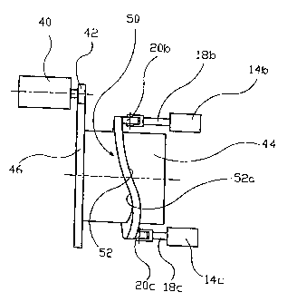
In an example of an embodiment of a piston pump shown
schematically in figures 7, 8 and 10, a motor 40, the
discharge shaft of which is provided with a cogwheel 42, is
designed to drive a rotatable drum 44 by the cogwheel meshing
with an outside rim 46 on the drum 44.
The outside of the drum 44 is further provided with an
encircling annular cam 50, one side of which is formed as a
profiled cam surface 52.
Outside of and in parallel with the drum 44 is provided at
least one piston cylinder 14b, 14c, where a piston (not
shown) is associated with a piston rod 18b, 18c, the free end
of which is designed to follow the cam surface 52 when the
drum 44 rotates, and thereby drive said piston (not shown) in
the cylinder 14b, 14c as explained previously.
In a preferred embodiment, six piston cylinders 14b, 14c,......
distributed equidistant around the drum 44 in a practical
embodiment of the invention will be connected to a common
manifold system. Each piston cylinder 14b, 14c, ...... is in a
known manner provided with the valves and couplings that are
required for the cylinder to be able to function as a pump
cylinder.
By such a six-cylinder piston pump, the drum is run by two
motors, one on either side of the drum 44.J
CA 02422039 2003-03-11
WO 02/23040 PCT/N001/00374
Figure 10 illustrates how the free outer end of the piston
rod 18, which end is actually constituted by that point on a
rotatable abutment roller 20b which is most remote from the
cylinder 14b, is brought to maintain resilient abutment
5 against the cam surface 52 of the annular cam 50. The
elastic/resilient abutment of the abutment roller 20b against
the cam surface 52 ensures that the peripheral area of the
roller at follows the non-circular course of the cam surface
52 360 degrees around the rotational axis of the drum 44 all
10 the time.
In order to achieve this possibility of resilient motion for
the roller 20b (and naturally also for the remaining abutment
rollers 20a, 20c, ......) in the axial direction of the
respective piston cylinders/piston rods, a bifurcated head
is 18b' for the rotatable support of the roller 20b is, by means
of a transverse bolt 54, formed at the end portion of the
actual piston rod in the constructive sense (the actual
piston rod end in the functional sense being formed by the
roller 20b, or more specifically the point of this which at
any time is the outermost of the periphery in the axial
direction of the piston rod 18b), one branch of which
bifurcated head 18b', via a holder 55, supports spring loaded
abutment means in the form of a small rotatable roller/wheel
56, the axis of which is parallel to the rotational axis of
the abutment roller 20b.
The peripheral surface of this smaller roller/wheel 56
resiliently supports and abuts the back 52a of the peripheral
surface of the cam 50, which surface, unlike the actual cam
surface 52, can follow a circular ring surface.
CA 02422039 2003-03-11
WO 02/23040 PCT/N001/00374
16
The spring 58 for this small roller/wheel may for instance be
constructed from several joined disk springs that are kept in
place inside a lying-down cup shaped part of a bearing part
60 that, among other things, supports a bifurcated end piece
62 for the support of the roller/wheel 56.
64 denotes an adjusting screw for adjusting the small
roller/wheel 56 relative to the cam 50 (the circular rear
side 52a of the cam) in the axial direction of the piston rod
18b, while 63 indicates a slide guide associated with the cam
a.o roller arrangement 50-20b.
As mentioned, said preferred embodiment includes six piston
cylinders spaced evenly (with the same angular distance)
around the drum, and these piston cylinders will in this
preferred embodiment with advantage be coupled to a common
manifold system.
The bifurcated head 18b', 18c' may in some embodiments be of
the same size as the cylinder 14a-14c...... at the other end of
the piston rod 18a-18c.......
The means of ensuring that the rollers 20 maintain their
contact with the opposite cam surface 52 at all times, take
various forms. In general, they must be capable of ensuring
that the pressure on the suction side is always high enough
to balance the frictional, gravitational and inertial forces
that seek to lift the roller off the cam and thereby
terminate the guiding co-operation between them. Figures 8
and 10 propose the use of a counter roller positioned to run
on the back of the cam 50. Alternatively, biasing may be
used, for instance pneumatic as indicated in figure 9, in
CA 02422039 2003-03-11
WO 02/23040 PCT/N001/00374
17
which an annular piston 16A wedged on an intermediate part on
the piston rod 18b, thus following its 18b movements, forces
the roller 20b against the cam 50 when the cylinder 14B is
pressurised upon supply of compressed air. Instead of this
pneumatic spring biasing embodiment, the biasing could have
been provided via a mechanical route.
By the embodiment according to figure 11, pneumatic springs
may be used, and the normally bifurcated holder 18b', 18c' at
the end of the piston rods 18a-18c of the respective
pneumatic cylinders 14a-14c may be formed so as to allow both
the abutment and counter roller 20b, 20c, in pairs 56
respectively, to be supported in each holder. Moreover, the
embodiment of figure 11 has the same driving and transmission
mechanism 40, 42, 46 as that of figure 7, the gearing 42, 46,
the drum 44 with a 360 degree encircling cam ring part 50 and
the three equidistantly (with an angular spacing of 120
degrees) positioned piston cylinders 14a-14c being supported
in two spaced apart, parallel side walls 82, 84 of a frame
structure, where a mounting plate 80 connects the two side
walls 82, 84. Reference number 44a denotes one of the axle
journals of the drum 44.