Sélection de la langue

Search

Sommaire du brevet 2422104 

Énoncé de désistement de responsabilité concernant l'information provenant de tiers

Une partie des informations de ce site Web a été fournie par des sources externes. Le gouvernement du Canada n'assume aucune responsabilité concernant la précision, l'actualité ou la fiabilité des informations fournies par les sources externes. Les utilisateurs qui désirent employer cette information devraient consulter directement la source des informations. Le contenu fourni par les sources externes n'est pas assujetti aux exigences sur les langues officielles, la protection des renseignements personnels et l'accessibilité.

Disponibilité de l'Abrégé et des Revendications

L'apparition de différences dans le texte et l'image des Revendications et de l'Abrégé dépend du moment auquel le document est publié. Les textes des Revendications et de l'Abrégé sont affichés :

  • lorsque la demande peut être examinée par le public;
  • lorsque le brevet est émis (délivrance).
(12) Demande de brevet: (11) CA 2422104
(54) Titre français: SYSTEME DE BLOCAGE D'UN ALIMENTATEUR VIBRANT D'UNE UNITE MOBILE DE CONCASSAGE PENDANT LE TRANSPORT
(54) Titre anglais: TRANSPORT LOCKING FOR A VIBRATING FEEDER OF A MOBILE CRUSHING UNIT
Statut: Réputée abandonnée et au-delà du délai pour le rétablissement - en attente de la réponse à l’avis de communication rejetée
Données bibliographiques
(51) Classification internationale des brevets (CIB):
  • B02C 21/02 (2006.01)
  • B02C 23/02 (2006.01)
  • E01C 19/05 (2006.01)
(72) Inventeurs :
  • NUORA, MARKO JUHANI (Finlande)
  • HYTTINEN, ESKO ARMAS (Finlande)
  • KOSKENKORVA, SEPPO JUHANI (Finlande)
  • KANKAANPAA, REIJO KALEVI (Finlande)
  • AALTONEN, JOONAS OSKARI (Finlande)
  • KOIVUMAKI, JOUNI MIKAEL (Finlande)
  • HULTTINEN, JOUNI JOUKO ELIAS (Finlande)
(73) Titulaires :
  • METSO MINERALS (TAMPERE) OY
(71) Demandeurs :
  • METSO MINERALS (TAMPERE) OY (Finlande)
(74) Agent: OSLER, HOSKIN & HARCOURT LLP
(74) Co-agent:
(45) Délivré:
(86) Date de dépôt PCT: 2002-08-26
(87) Mise à la disponibilité du public: 2003-03-06
Requête d'examen: 2003-09-15
Licence disponible: S.O.
Cédé au domaine public: S.O.
(25) Langue des documents déposés: Anglais

Traité de coopération en matière de brevets (PCT): Oui
(86) Numéro de la demande PCT: PCT/FI2002/000690
(87) Numéro de publication internationale PCT: WO 2003018206
(85) Entrée nationale: 2003-03-11

(30) Données de priorité de la demande:
Numéro de la demande Pays / territoire Date
20011740 (Finlande) 2001-08-31

Abrégés

Abrégé français

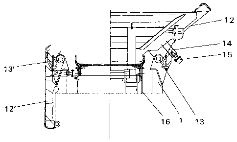
L'invention porte sur un système de blocage d'un alimentateur vibrant d'une unité mobile de concassage pendant le transport. Ce système de blocage utilise les parois latérales à rotation vers le bas de la trémie de l'alimentateur vibrant qui sont montées pivotantes sur l'ossature de l'unité de concassage. Les parois latérales, en position inférieure, sont adaptées pour bloquer l'alimentateur vibrant de manière rigide contre l'ossature de l'unité de concassage. Cette invention propose une technique rapide et simple pour bloquer un alimentateur vibrant pendant le transport.


Abrégé anglais


A transport locking arrangement is disclosed for a vibrating feeder of a
mobile crushing unit, the transport locking arrangement utilizing the downward
rotatable sidewalls of the feeder hopper of the vibrating feeder that are
hingedly mounted on the framework of said crushing unit, whereby the sidewalls
in their lower position are adapted to lock the vibrating feeder substantially
rigidly to the framework of the crushing unit. The invention offers a rapid
and easy technique of transport locking for a vibrating feeder.

Revendications

Note : Les revendications sont présentées dans la langue officielle dans laquelle elles ont été soumises.


7
claims
1. A transport locking arrangement for a vibrating feeder of a mobile crushing
unit,
the crushing unit including a feeder hopper (3) formed by downward rotatable
sidewalls (12, 12') hingedly mounted on the framework of said crushing unit,
characterized in that at least one of said downward rotatable sidewalls of the
feeder
hopper in its lower position is capable of locking the vibrating feeder (2)
substantially rigidly to the framework (1) of the crushing unit.
2. The transport locking arrangement of claim 1, characterized in that the
locking
arrangement is frictionally secured.
3. The transport locking arrangement of claim 1, characterized in that the
locking
arrangement is secured by elements having compatibly mating shapes.
4. The transport locking arrangement of any one of claims 1-3, characterized
in that
the exterior surface of at least one of said downward-rotatable sidewalls (12,
12') of
the feeder hopper (3) has mounted thereon at least one element (14) capable of
locking the vibrating feeder in the lower position of said sidewall to the
framework
(1) of the mobile crushing unit.
5. The transport locking arrangement of any one of claims 1-3, characterized
in that
at least one of the exterior surfaces of the feed chute (16) of the vibrating
feeder has
mounted thereon at least one element that with the feeder hopper (3) of the
vibrating
feeder having at least one of its downward-rotatable sidewalk (12, 12')
rotated in its
lower position locks the vibrating feeder to the framework (1) of the mobile
crushing
unit.
6. The transport locking arrangement of any one of claims 1-3, characterized
in that
on the framework (1) of the crushing unit is mounted at least one locking
element
that with the feeder hopper (3) of the vibrating feeder having at least one of
its
downward-rotatable sidewalls (12, 12') rotated in its lower position locks the

8
vibrating feeder to the framework of the mobile crushing unit.
7. The transport locking arrangement of any one of claims 1-3, characterized
in that
the elements implementing the transport locking arrangement are mounted on
both
the downward-rotatable sidewall (12, 12') of the feeder hopper and the feed
chute
(16) of the vibrating feeder.
8. The transport locking arrangement of any one of claims 4-7, characterized
in that
the downward-rotatable sidewalk of the vibrating feeder used for implementing
the
transport locking arrangement are the longitudinal sidewalls of the feeder
hopper.
9. The transport locking arrangement of any one of foregoing claims,
characterized
in that the locking member is a rod-shaped element adapted to connect for
transporta-
tion at least one of the downward-rotatable sidewalls (12, 12') of said feeder
hopper
(3) and said feed chute (16) of the vibrating feeder with each other.

Description

Note : Les descriptions sont présentées dans la langue officielle dans laquelle elles ont été soumises.


CA 02422104 2003-03-11
a
Transport locking for a vibrating feeder of a mobile crushing unit
The present invention relates to mobile crushing units. More specifically, the
invention relates to a transport locking arrangement for the vibrating feeder
of such a
mobile crushing unit.
Conventionally, a mobile crushing unit comprises a framework having connected
thereto a feeder device, a feed hopper, a crusher, a power unit and a
discharge
conveyor of crushed material.
The feeder device most generally used in mobile crushing units is a vibrating
feeder
that in its simplest form comprises a feeder hopper, a vibrator and springs on
which
the vibratory feeder rests on the crushing unit framework. During the
operation of the
crushing unit, material to be crushed is fed onto the vibrating feeder that by
vibration
1 s conveys the material as a uniform flow into the crusher. Generally, a
portion of the
feed hopper bottom is provided with a grate that removes from the infeed
material
flow the fine aggregate fraction that might disturb the operation of the
crusher. The
small-sized aggregate falls through the classifier trough grate away from the
feed
hopper before the aggregate proceeds to the crusher proper. Generally, the
free
aggregate removed via the grate is passed onto the crushed material discharge
conveyor or onto a separate fine aggregate discharge conveyor that transports
the
fme aggregate away from crushing unit. The coarse aggregate to be crushed
proceeds
in the vibrating feeder to the crusher for comminution therein and then
further onto
the crushed aggregate discharge conveyor that removes the processed material
form
the crushing unit.
For easy infeed of material, the crushing unit framework generally carries an
infeed
hopper that directs the infeed material flow onto the vibrating feeder.
Conventional-
1y, the transportability of the crushing unit is enhanced by constructing the
infeed
3o hopper such that its walls are downward foldable for the duration of the
crushing unit
hauling by having the walls mounted on hinges that join the infeed hopper
walls to
the crushing unit framework.

CA 02422104 2003-03-11
2
15
Generally, the reciprocating motion of the vibrating feeder can be adjusted by
con-
trolling the operating frequency of feeder actuator and the weight and
location of the
eccentric masses of the vibrator. However, the movements of the vibrating
feeder
during crushing unit transportation are difficult to control. The major
factors
generating these random motions are the irregular contour of the road surface
and the
hauling speed of the crushing unit. Herein, there is a risk of the vibrating
feeder
jumping off from its support springs during transportation. This may cause
damage
to the feeder or even to the entire crushing unit.
To prevent damage during hauling, it is customary to secure the vibrating
feeder to
the crushing unit framework by different kinds of transport locking means such
as
wedges, cables, turnbuckle screws and the like securing devices. These methods
are,
however, clumsy and tedious in practical use.
The novel transport locking method disclosed herein offers a rapid and
uncomplicat-
ed way of securing a vibrating feeder during transportation. The transport
locking
arrangement according to the invention advantageously utilizes the downward
hingedly rotatable sidewalls of the crushing unit feeder hopper that in their
lowered
position secure the vibrating feeder'to the framework of the mobile crushing
unit
with the help of locking means. In the.present context, the term locking must
be
understood to comprise a securing facility capable locking the vibrating
feeder to the
crushing unit framework in a substantially rigid fashion. The securing
facility may be
implemented using means capable of engaging frictionally or by compatibly
mating
surfaces of the locking elements.
More specifically, the transport locking arrangement according to the
invention is
characterized by what is stated in the characterizing part of claim 1.
3o Next, the invention will be examined in greater detail by making reference
to the
attached figures wherein

CA 02422104 2003-03-11
3
FIG. 1 shows a mobile crushing unit in elevational side view with the feeder
and
crusher parts illustrated in sectional views;
FIG. 2 shows an exemplifying embodiment of a conventional transport locking
assembly of a vibrating feeder;
FIG. 3 shows a fractionally engaging transport locking assembly according to
the
invention;
1o FIG. 4 shows a mating-element-engaging transport locking assembly according
to
the invention; and
FIG. 5 shows a sladable-element-engaging assembly for the transport locking
arrangement according to the invention.
Referring to FIG. 1, an exemplary embodiment of a mobile crushing unit
comprises a
framework 1, a vibrating feeder 2, a feeder hopper 3, a classification trough
4, a jaw
crusher 5, a power unit 6, a crushed material discharge conveyor 7 and a fine
aggregate discharge conveyor 8.
During the operation of the crushing unit, material to be crushed in fed onto
the
vibrating feeder 2 by means of a bucket loader or conveyor, for instance. To
make
the loading of the material easier, a feeder hopper 3 is used having its walls
hingedly
mounted on the crushing unit framework and, for the duration of the crushing
operation, rotated into an upper position as a chute. The vibrating feeder
sets the
material to be crushed into a vibratory motion in order to separate away from
the
material flow the fine aggregate fraction such as sand and small stones that
disturb
the function of the crusher. The fine aggregate falls down through the grate
of the
vibrating feeder and is directed by means of a classifying trough 4 either
onto a fine
3o aggregate discharge conveyor 8 running at right angles to the classifier
or, as shown
in the diagram to a crushed materaat discharge conveyor 7 that removes the
crushed
material from the crushing unit. The rest of the material flow to be crushed
proceeds

CA 02422104 2003-03-11
4
along the vibrating feeder into the crusher S, wherein the material is crushed
into
desired aggregate size. The actuating power of the crusher, feeder and
conveyors is
delivered by a power unit 6. After cnzshing, the stone aggregate falls onto
the
crushed material discharge conveyor 7 adapted to run below the crusher so as
to
remove the crushed material from the crushing unit.
Now referring to FIG. 2, the exemplifying embodiment of a conventional
transport
locking arrangement shown therein fox a vibrating feeder of a crushing unit is
imple-
mented with the help of locking means 9, 10 located at both ends of the
vibrating
feeder 2 and on both sides of the vibrating feeder. The locking means comprise
two
parts of which the lower part 9 is mounted on the framework I of the crushing
unit.
The upper part 10 of the locking means is pivotally connected to the lower
part 9 by
a pivot pin screw.
~ 5 In its operating position, the vibrating feeder 2 rests supported by its
springs 1 I on
the crushing unit framework 1. To engage the transport locking of the
vibrating
feeder, the screw of the pivotal joint between the upper part 10 and the lower
part 9
of the locking means is slightly loosened and the upper part is rotated until
its notch
engages a bolt mounted on the frame of the vibrating feeder 2. Next, the
screws are
2o tightened to lock the pivotal joints between the upper and lower parts and
to secure
the end of the upper part of the locking means to the frame of the vibrating
feeder.
This kind of transport locking arrangement involves tedious and slow worksteps
to
engage and disengage the locking.
25 . In FIG. 3 is shown a frictionally engaging transport locking arrangement
according
to the invention wherein the main elements are the sidewalk 12, 12' of the
feeder
hopper, hinges 13, 13' of the sidewalls, a peg 14 serving as the locking
member, an
elastic pad I S mounted on the end of the locking member, a framework 1 of the
crushing unit and a feed chute 16 of the vibrating feeder.
The pegs 14 serving as the locking members are rigidly mounted on the exterior
sur-
faces 12, 12' of the feeder hopper sidewalls. When rotated into their lower
position

CA 02422104 2003-03-11
about the hinges 13, 13' mounted on the crushing unit framework 1, the weight
of the
feeder hopper sidewall pushes the elastic pad 15 mounted on the end of the peg
acting as the locking member tightly against the wall of the feed chute 16.
Having
both feeder hopper sidewalls rotated into their lower positions, the vibrating
feeder is
5 frictionally secured to the crushing unit framework 1 ready for
transportation.
In FIG. 4 is illustrated an embodiment of the transport locking arrangement
accord-
ing to the invention based on locking by mating elements, whereby the walls of
the
feed chute of the vibrating feeder is provided with a hole 17. In compatible
position
therewith is mounted a peg 14 on the sidewalls 12, 12' of feeder hopper.
Resultingly,
lowering the feeder hopper sidewaIl into the transport position causes the peg
to
engage with the hole made on the feed chute wall, whereby the compatible
shapes of
the peg and the hole lock the vibrating feeder to the crushing unit framework.
~5 In FIG. 5 is shown an embodiment of the locking arrangement according to
the
invention based on nonrigid mounting of the locking members, whereby the
locking
member 18 is connected to the crushing unit framework 1 by a springed mount
19.
Then, having the feeder hopper sidewalls 12, 12' rotated into their lower
positions
makes the peg 20 mounted on the sidewall to push the locking member 18 against
the
2o wall of the feed chute 16 of the vibrating feeder. Resultingly, the locking
member 18
clamped between the peg 20 and the wall of the feed chute 16 imposes
sufficient
friction to secure the feed chute in a rigid fashion against the feeder hopper
sidewall
and, via the hinge of the hopper sidewall, to the crushing unit framework.
25 In a similar fashion, the springed mounting 19 of the locking member 18 to
the
crushing unit framework 1 may be replaced by a slidable mount that permits
lateral
movement of the locking member at right angles to the crushing unit framework.
Furthermore, the slidable engaging assembly shown in FIG. 5 may be implemented
3o using securing elements of compatible shapes or frictional engaging similar
to those
of FIGS. 3 and 4.

CA 02422104 2003-03-11
6
The invention is not limited as to the number of locking members adapted
between
the vibrating feeder and the crushing unit framework to secure locking
therebetween
but rather, the number of locking members may be one or more on each one of
the
downward-rotatable sidewalls of the feeder hopper. Furthermore, there is no
need to
use discrete locking members provided that the feed chute walls of the
vibrating
feeder and the framework of the crushing unit can be shaped compatibly locking
with
each other in a rigid fashion when the sidewalls are rotated into the lower
position.
Moreover, the invention is not limited as to the fashion the sidewalls of the
feeder
hopper are adapted movable. Instead, the feeder hopper sidewalls may
alternatively
be elevated by a separate lifting means and lowered gravitationally.
Nevertheless, the
sidewalls must be adapted lockable in their lower positions. Advantageous
applica-
tion of the invention are found in crushing units having the sidewalls of the
feeder
hopper made movable by hydraulic cylinders, whereby no separate lifting means
is
~ 5 needed for elevating the sidewalls into their operating position and no
locking
members are needed for securing the sidewalls in their transport position.

Dessin représentatif
Une figure unique qui représente un dessin illustrant l'invention.
États administratifs

2024-08-01 : Dans le cadre de la transition vers les Brevets de nouvelle génération (BNG), la base de données sur les brevets canadiens (BDBC) contient désormais un Historique d'événement plus détaillé, qui reproduit le Journal des événements de notre nouvelle solution interne.

Veuillez noter que les événements débutant par « Inactive : » se réfèrent à des événements qui ne sont plus utilisés dans notre nouvelle solution interne.

Pour une meilleure compréhension de l'état de la demande ou brevet qui figure sur cette page, la rubrique Mise en garde , et les descriptions de Brevet , Historique d'événement , Taxes périodiques et Historique des paiements devraient être consultées.

Historique d'événement

Description Date
Inactive : Regroupement d'agents 2013-10-24
Demande non rétablie avant l'échéance 2006-08-28
Le délai pour l'annulation est expiré 2006-08-28
Inactive : CIB de MCD 2006-03-12
Réputée abandonnée - omission de répondre à un avis sur les taxes pour le maintien en état 2005-08-26
Lettre envoyée 2003-10-07
Toutes les exigences pour l'examen - jugée conforme 2003-09-15
Exigences pour une requête d'examen - jugée conforme 2003-09-15
Requête d'examen reçue 2003-09-15
Lettre envoyée 2003-07-07
Inactive : Transfert individuel 2003-06-03
Inactive : Correspondance - Formalités 2003-06-03
Inactive : Page couverture publiée 2003-05-13
Inactive : Lettre de courtoisie - Preuve 2003-05-13
Inactive : Notice - Entrée phase nat. - Pas de RE 2003-05-12
Inactive : Notice - Entrée phase nat. - Pas de RE 2003-05-08
Demande reçue - PCT 2003-04-09
Exigences pour l'entrée dans la phase nationale - jugée conforme 2003-03-11
Demande publiée (accessible au public) 2003-03-06

Historique d'abandonnement

Date d'abandonnement Raison Date de rétablissement
2005-08-26

Taxes périodiques

Le dernier paiement a été reçu le 2004-08-24

Avis : Si le paiement en totalité n'a pas été reçu au plus tard à la date indiquée, une taxe supplémentaire peut être imposée, soit une des taxes suivantes :

  • taxe de rétablissement ;
  • taxe pour paiement en souffrance ; ou
  • taxe additionnelle pour le renversement d'une péremption réputée.

Veuillez vous référer à la page web des taxes sur les brevets de l'OPIC pour voir tous les montants actuels des taxes.

Historique des taxes

Type de taxes Anniversaire Échéance Date payée
Taxe nationale de base - générale 2003-03-11
Enregistrement d'un document 2003-06-03
Requête d'examen - générale 2003-09-15
TM (demande, 2e anniv.) - générale 02 2004-08-26 2004-08-24
Titulaires au dossier

Les titulaires actuels et antérieures au dossier sont affichés en ordre alphabétique.

Titulaires actuels au dossier
METSO MINERALS (TAMPERE) OY
Titulaires antérieures au dossier
ESKO ARMAS HYTTINEN
JOONAS OSKARI AALTONEN
JOUNI JOUKO ELIAS HULTTINEN
JOUNI MIKAEL KOIVUMAKI
MARKO JUHANI NUORA
REIJO KALEVI KANKAANPAA
SEPPO JUHANI KOSKENKORVA
Les propriétaires antérieurs qui ne figurent pas dans la liste des « Propriétaires au dossier » apparaîtront dans d'autres documents au dossier.
Documents

Pour visionner les fichiers sélectionnés, entrer le code reCAPTCHA :


Pour visualiser une image, cliquer sur un lien dans la colonne description du document. Pour télécharger l'image (les images), cliquer l'une ou plusieurs cases à cocher dans la première colonne et ensuite cliquer sur le bouton "Télécharger sélection en format PDF (archive Zip)" ou le bouton "Télécharger sélection (en un fichier PDF fusionné)".

Liste des documents de brevet publiés et non publiés sur la BDBC .

Si vous avez des difficultés à accéder au contenu, veuillez communiquer avec le Centre de services à la clientèle au 1-866-997-1936, ou envoyer un courriel au Centre de service à la clientèle de l'OPIC.


Description du
Document 
Date
(aaaa-mm-jj) 
Nombre de pages   Taille de l'image (Ko) 
Description 2003-03-11 6 290
Revendications 2003-03-11 2 71
Dessins 2003-03-11 5 131
Abrégé 2003-03-11 1 14
Dessin représentatif 2003-05-13 1 12
Page couverture 2003-05-13 1 46
Avis d'entree dans la phase nationale 2003-05-12 1 189
Courtoisie - Certificat d'enregistrement (document(s) connexe(s)) 2003-07-07 1 105
Accusé de réception de la requête d'examen 2003-10-07 1 173
Rappel de taxe de maintien due 2004-04-27 1 110
Courtoisie - Lettre d'abandon (taxe de maintien en état) 2005-10-24 1 176
PCT 2003-03-11 3 121
Correspondance 2003-05-12 1 25
Correspondance 2003-06-03 1 58
Taxes 2004-08-24 1 42