Note : Les descriptions sont présentées dans la langue officielle dans laquelle elles ont été soumises.
CA 02422318 2003-03-17
POWER TOOL WITH PORTABLE POWER SOURCE
FIELD OF THE INVENTION
This invention relates generally to a power tool having a removable, portable
power source and, more particularly to a hand held polisher having a
removable, portable
power source in association with its housing.
BACKGROUND OF THE INVENTION
The tool industry offers a variety of cordless power tools for perfonming work
on
various types of workpieces. Each of these tools offer the advantage of being
operated
without a cord and/or remote from a generator or a hard wired power source,
such as a
conventional outlet. For example, cordless power tools allow the tool operator
to use the
tool without regard for both the proximity to a power outlet or to the length
of available
power. Battery-powered tools also allow the tool operator to operate the tool
without
interference and distracting concerns associated with an attached power cord.
Known power tools commonly locate the battery at the handle of the tool. This
often tends to make the tool unbalanced and cumbersome to operate due to the
unbalanced and oversized weight distribution. For example, a 14.4-volt or 18-
volt
battery located at the end of a power tool handle increases the weight
distribution such
that the tool becomes difficult to hold and operate steady for appropriate
periods of time
due to operator fatigue. This is of particular concern when working with
generally
vertical workpieces, such as a car door, as opposed to generally horizontal
workpieces,
such as a board laying flat on a workbench.
Experience also has revealed that an unbalanced tool renders it difficult to
work
evenlyon a workpiece. For example, in the case ofpolishers, it is important to
apply wax
evenly over the workpiece and to polish and buff the workpiece evenly
thereafter. If the
power tool is unbalanced, the task of working the tool evenly about the
workpiece
becomes more difficult for the operator and has the tendency to make the tool
work
heavier on the side nearest the battery (the heavier portion of the tool).
CA 02422318 2003-03-17
Another shortcoming associated with handle located batteries is the tendency
to
require the handle to be larger than necessary. This compounds the difficulty
and
discomfort in holding the tool. For example, the size of a conventional
battery pack often
increases the handle size by at least 30 percent. The enlarged handle
configuration tends
to render the power tool more difficult and uncomfortable to handle.
An even further shortcoming with handle-mounted batteries is the limitation on
the ability to provide a variety of gripping locations. For example, the
addition of a
battery pack to the handle often shortens the length of the portion of the
handle on which
one can grip. This results in reducing the number of different gripping
positions on the
handle.
Since a wide variety of individuals will be using the power tool, the
shortcomings
from having the battery pack in the handle make it difficult to meet the
variety of
demands each operator may have for the power tool.
Thus, there is a need for a power tool having a portable power source to
enable
the tool to be used in a variety of locations for a variety of different
applications and in
a convenient, efficient and effective manner.
SUMMARY OF THE INVENT10N
A power tool in accordance with the invention includes a housing having an
internal compartment with a motor therein, a handle connected to the housing
for
maneuvering the power tool, a working element connected to and driven by the
motor to
work on a workpiece, and a removable portable power source having a first
position
wherein the power source is located primarily in the internal compartment of
the housing
and being electrically connected to the motor to provide power to the motor
for driving
the working element and a second position wherein the power source is located
remotely
from the housing and detached electrically from the motor. A preferred
embodiment of
the tool also includes a battery release mechanism or lock associated with the
housing
and the removable portable power source. The lock has a lock position that
prevents the
-2-
CA 02422318 2003-03-17
removable portable power source from unintentionally becoming separated from
the
power tool, and an unlock position that enables the removable portable power
source to
be removed from the internal compartment of the housing and separated from the
power
tool. , The lock may be connected to the housing and configured such that it
remains
connected to the housing when the removable portable power source is removed
from the
internal compartment, or may be connected to the removable portable power
source and
configured such that it remains connected to the removable portable power
source when
the removable portable power source is removed from the internal compartment
of the
housing.
The housing may also include a detachable portion that detaches at least in
part
from the housing to enable the removable portable power source to be
selectively
removed from the internal compartment of the housing. In a preferred
embodiment, the
detachable portion of the housing is attached to the removable portable power
source and
detaches entirely from the housing when the removable portable power source is
removed
from the internal compartment of the housing.
Ideally, the power tool will use a rechargeable removable portable power
source
so that the removable portable power source may be reused with the power tool.
As such,
the power tool may be configured with an electrical connector which is
electrically
connected to the motor for enabling the motor to be powered by an alternate
power
source located externally of the power tool when the removable portable power
source
is dissipated, or when the operator so desires to operate the power tool from
an alternate
power source. For example, the power tool may be connected via a power cord to
an
alternate power source located externally of the power tool. The alternate
power source
may be rechargeable and/or may require the use of a converter to convert the
power
output of the alternate power source from a first type of power to a second
type of power
for powering the motor.
The power tool may also include an outer elastomer surface, such as an
elastomer
injected overmolding, to facilitate enhanced gripping for control over the
power tool.
-3-
CA 02422318 2003-03-17
The handle may also be generally U-shaped to allow an operator a range of
locations
about the housing to facilitate an effective two-handed grip to maintain
control over the
power tool. In one embodiment, the handle may be designed with first and
second end
portions that are enlarged with respect to the remainder of the handle in
order to provide
the operator with a variety of grip sizes to choose from.
The power tool may also include an actuator electrically connected to the
motor
for activating and deactivating the power tool. The actuator may be positioned
in a
bridging member which connects the handle and the housing of the power tool,
or may
be recessed in the bridging member connecting the handle and the housing of
the power
tool in order to prevent accidental actuating thereof.
BRIEF DESCRIPTION OF THE DRAWINGS
FIG. 1 is a perspective view of a power tool embodying the features of
invention;
FIG. 2 is a front elevational view of the power tool of FIG. 1;
FIG. 3 is a leR-side elevational view of the power tool of FIG. 1;
FIG. 4 is a right side elevational view of the power tool of FIG. 1;
FIG. 5 is a plan view of the power tool of FIG. 1;
FIG. 6 is an exploded view of the power tool of FIG. 1;
FIG. 7 is a cross sectional view of the power tool of FIG. 1 taken along line
7-7
in FIG. 3;
FIG. 8 is a cross sectional view of the operated power tool of FIG. 1 taken
along
line 8-8 in F1G. 2;
FIG. 9 is an enlarged view of a portion of FIG. 8 to illustrate a power source
release mechanism;
FIG. 10 is a cross-sectional view of the power tool of FIG. 1 taken along line
10-
10 in FIG. 2;
FIG. 11 is a perspective view of an alternate power tool embodying features of
the present invention;
-4-
CA 02422318 2003-03-17
FIG. 12 is a front elevational view of the power tool of FIG. 11;
FIG. 13 is a right-side elevational view of the power tool of FIG. 11;
FIG. 14 is a plan view of the power tool of FIG. 11;
FIG. 15 is an exploded view of the power tool of FIG. 11;
~ FIG. 16 is a cross-sectional view of the power tool of FIG. 11 taken along
line 16-
16 in FIG. 12;
FIGS.17A-D are perspective views of alternate power source release mechanisms
embodying feature of the present invention;
FIG. 18 is a perspective view of an alternate power tool in accordance with
the
invention showing a modular power cord; and
FIG. 19 is a bottom view of the power tool of FIG. 1.
DETAILED DESCRIPTION OF THE PREFERRED EMBODIMENTS
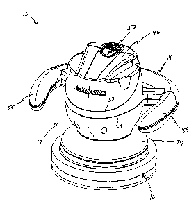
In FIGS. 1-10, there is illustrated a power tool 10 with a portable power
source
for working on a workpiece (e.g., waxing, buffing, polishing, etc.) in
accordance with the
present invention. The power tool 10 includes a housing 12, a generally U-
shaped handle
14 connected to the housing 12, and a work element, such as a pad 16, for
working on a
desired workpiece, such as the body of a automobile or hull of a boat. The
power tool
10 includes a symmetrical design about a vertical reference plane (not shown)
extending
centrally from a forward end 18a to a rearward end 18b (see FIGS. 3 and 4).
The cross
section illustrated in FIG. 8 is taken along the vertical reference plane.
The housing 12 includes an upper housing shell 20 and a lower housing shell 22
which, when connected to each other, interface along a part line 24. The upper
housing
shell 20 and lower housing shell 22 can be made of any suitably lightweight
material and
are preferably molded plastic parts. The upper housing shell 20 and the lower
housing
shell 22 are secured together by a number of screws recessed in the lower
surface of the
handle 14. Collectively the upper and lower housing shells 20 and 22 define an
internal
cavity 26. A motor 28 is disposed in the cavity 26 and is connected to a motor
or gear
-5-
CA 02422318 2003-03-17
mounting plate 30 also located within cavity 26. The mounting plate 30 is
preferably
secured to the inside of the lower housing shell 22.
The motor 28 is mechanically connected to the pad 16 and is capable of driving
the pad 16 in an orbital path below the housing 12. More particularly, a motor
output
shaft ~28a drives a first gear or pinion gear 32, which, in turn, drives a
second gear or
driven gear 34. The gears 32 and 34 are at least partially covered by gear
casing or cover
42 in order to protect the gears from contaminants, such as dust or other
residual panicles
from materials, such as wax, which are used on the workpiece in conjunction
with the
tool 10. A gear shaft 36 has a first end connected to the driven gear 34 and a
second end
to a counterweight 38. Rotation of the gear shaft 36 results in rotation of
the
counterweight 38 about the shaft 36. Moreover, rotation of counterweight 38
causes a
corresponding rotation about the z-axis of the work element such as pad 16,
which is
connected to the counterweight 38. Bearings 40a-d are used to reduce the
friction of the
rotating members and allow the motor to operate more efficiently.
The housing 12 further defines a power source compartment 44 for holding a
removable power source such as battery or battery pack 46. For example, as
illustrated
in FIG. 6, the removable power source 46 includes a lower battery pack housing
46a,
multiple battery celis 46b, and an upper battery pack cover 46c. The battery
pack housing
46a is complimentary shaped to fit within the housing 12, and includes a lower
protruding member 46d extending downward from and below the lower housing 46a.
When assembled, the battery cells 46b are inserted into the lower housing 46a,
which is
attached to the cover 46c via fasteners, such as screws 46e. The battery pack
lower
housing 46a is generally U-shaped or V-shaped with the protruding member
extending
downward below the general apex region ofthe U or V-shaped portion. The
battery-style
power source 46 is preferably designed to hold ten 1.2-volt cells and two
dummy cells
to produce a 12-volt power source, or twelve 1.2-volt cells to produce a 14.4-
volt power
source. In each instance, two cells are stored side-by-side in the lower
protruding
member 46d. This configuration allows for two separate models of the tool 10
to be
-6-
CA 02422318 2003-03-17
provided from the same platform, thereby reducing the costs associated with
offering
multiple models.
The contacts or terminals 55 forthe power source 46 are located on the bottom
and/or lower side surfaces of the protruding member 46d, and are positioned to
engage
conresponding electrical contacts, such as spring contacts 56. The contacts
56, for
example, are mounted on a printed circuit board (PCB) 58, which is connected
to the
inside of the power source compartment. Thi s configuration allows
conventional battery
pack-type terminal configurations to be used, thereby further reducing the
cost associated
with manufacturing the apparatus 10.
The inside surface of the battery compartment 44 is separated from the
internal
cavity by a plastic lining wall or liner 48, which is configured to closely
correspond to
the shape of the power source pack 46. The shape of the liner 48 aids to
properly guide
the power source in and out of the compartment 44. For example, with reference
to the
embodiment illustrated in FIG. 6, the battery pack 46 can only be inserted
into the
compartment 44 with one orientation, i.e., with the protruding member of the
housing 46a
extending downward and the U or V-shape of the bariery pack housing 46a
matching the
corresponding curved shape of the liner 48. Such configuration eliminates
operator
confusion with respect to installing the battery pack 46 and inadvertent or
accidental
electrical issues due to handling and installation of the battery pack 46.
The upper housing shell 20 includes an inner surface 20a which extends inward
to combine with at least a portion of liner 48 to define a generally oval
shaped recess to
receive the protrusion 46d ofbatterypack 46. The electrical contacts or
terminals 56 are
located near the bottom of the recess 46f, where the PCB S8 is connected to a
lower
tongue portion of the liner 48. The remote location of the terminals 56
renders it even
more difficult to improperly install and connect the bariery 46 to the tool
10.
The power source 46 and the upper housing shell 20 interface at a parting line
50
when the power source 46 is properly associated with the tool 10. The parting
line 50
runs about the periphery of the opening to the power source compartment 44. In
other
CA 02422318 2003-03-17
words, the parting line 50 defines the outer periphery of the cover 46c when
the power
source 46 is installed. The power source 46 is released by operating the
release
mechanism or Lock 52 located on the tolr of the housing 12 adjacent the
parting line 50.
By actuating the release mechanism 52, a lock member is removed from
engagement with
a lock engaging surface so that the power sowce 46 can be removed from housing
12.
As illustrated in FIGS. 6, 8 and 9, the power sowce 46 is removed by sliding a
button portion 52a of the release mechanism 52 toward the rear 18b of the
housing 12.
This sliding action causes a shoulder or hook portion 52b to disengage the
lock engaging
surface or lip 52c of power sowce 46. The shoulder portion 52b is normally
biased to a
lock position by a spring member 53 positioned between a vertical wall 48a of
the liner
48 and a vertical wall 52d extending downward from the button portion 52a of
the release
mechanism 52. The length of travel of the button portion 52a in the locking
direction is
limited by an end stop 48b which also extends upward from the liner 48. This
action
maintains the spring 53 under a minimal amount of compression so that it
remains in
position between the vertical walls 48a and 52d, including when the power
source 46 has
been removed from the tool 10. Thus, when the release mechanism 52 is actuated
the
button portion 52a, shoulder 52b and vertical wall 52d are moved in the
direction of the
reference arrow 57. As a result, the spring 53 is compressed, and the shoulder
52b
disengages the lip portion 52c so that the power source 46 can be removed from
the tool
10. A guide member 52e extends out from the front of the button portion 52a
and travels
between the top end of the vertical wall 48a and another surface on the inside
of the
upper housing shell 20 to guide the movement made by the release mechanism 52
in a
generally linear fashion.
Once the release mechanism 52 has been actuated, the operator may remove the
power source 46 by grasping the shoulder or gripping grooves 54 (FIG. 2) of
the power
source 46, which are formed along the sides of the raised portion 60 of cover
46c. The
gripping grooves 54 form an ergonomic handle which the operator may use to
pull the
power source 46 from the tool 10. In a preferred fotTn, the spacing between
the gripping
_g_
CA 02422318 2003-03-17
grooves 54 tapers toward one another as they extend from the rear 1 Sb ofthe
housing 12
to the front 18b of the housing. This provides a grip of varying widths to
accommodate
operators with differing hand sizes. The raised portion 60 also tapers
downward as it
approaches the front of the housing 18a so as to become generally flush with
the top edge
of the housing 12 at the front of the tool 10. To assist in the removal of the
power source
46, the button portion 52a defines an inclined recessed area 52r which
facilitates an
operator's ability to efficiently and effectively actuate the release
mechanism 52a. Thus,
the power source 46 can be removed with a single hand. For example, an
operator may
press or slide the release switch 52 with his or her index finger and gasp the
gripping
grooves 54 with the thumb and remaining fingers. Alternatively, the operator
may
remove the power source 46 by grasping or palming the outer surfaces of the
power
source with his or her hand and actuating the release mechanism 52 with either
the index
finger on the same hand or with a finger or thumb from the other hand. In
addition, the
power source 46 may further include indentation or grooves 84 which provide
enhanced
engagement surfaces for the operator to position his or her fingers on the
battery cover
46c to facilitate effective removal and installation of the power source 46.
When the power source 46 is installed, the spring action ofthe release
mechanism
52 allows the power source 46 to snap into its secure position in the housing
12. More
specifically, the shoulder 52b and the lip portion 52c of the release
mechanism 52 have
cooperating cam surfaces so that when the shoulder 52b is moved a sufficient
amount,
the lip portion 52c passes below the shoulder when the power sowce 46 is
installed into
the housing 12. Once the lip 52c has cleared the shoulder 52b, the spring 53
biases the
shoulder 52b into engagement with the lip 52c so that the power source 46 is
secwed in
the housing 12. The power source 46 also has at least one tongue member or
post 86 for
inserting into a mating recess located on the housing 12 to help secure and
align the
battery pack 46 in the housing 12. As illustrated in FIGS. 6 and 8, a
preferred form of
tongue member 86 has a rectangular cross-section and a tapered tip for sliding
in and out
of a cooperating aperture 86a defined by the housing shell 20. The tapered tip
enables
-9-
CA 02422318 2003-03-17
effective insertion of the tongue member 86 into the recess 86a. Other tongue
members
or alignment tabs may be positioned about the power source 46 in order to help
align
and/or secure the power source 46 in the-housing 12. For example in FIG. 6,
additional
tabs appear on the side of the power source 46 to assist the tongue 86. In
alternate
embodiments, the tongue and/or tabs may extend from the housing 12 and the
recesses
maybe defined by the power source 46. In even other embodiments, a combination
of
tongue andlor tab members and recesses may appear on both the power source 46
and the
housing 12.
As illustrated in FIGS. 1-10, the remainder of the upper housing portion 20 is
contoured to coordinate with the cover 46c of power source 46. For example,
the
sidewalls of the upper housing shell 20, which define the battery compartment
44
opening and form part of mating line 50, are arcuately shaped to match the
corresponding
sidewalls of cover 46c. Furthermore, the rear sidewall of the upper housing
shell 20
contains recesses or shoulder portions which correspond to the gripping
portions 54 of
the cover 46c.
The lower housing shell 22 is generally bowl-shaped with a planar bottom wall
22a. An arcuate shield or skirt 74 is attached to the bottom wall 22a by
screws 75. As
illustrated in FIG. 7, the upper and lower housing shells 20 and 22 are
connected in a
tongue and groove fashion along the parting line 24 and, when mated together,
define the
internal cavity 26 to house the motor and gearing. The lower wall 22a (FIG.
19) of the
lower housing shell 22 and the shield member 74 each define an opening 22b,
74a,
respectively, which are aligned and through which at least a portion of the
gear/motor
mount 30 passes.
As illustrated in FIGS. 6 and 8, the gear/motor mount 30 has a lower planar
ZS portion 68 with a frusto-conical portion 70 extending downward therefrom,
and an
annular wall portion 72 extending upward therefrom. The frusto-conical portion
70
defines a hollow inner region in which bearings 40a and 40b are disposed, and
a
passageway for the gear shaft 36. Due to an internal shoulder portion 77 in
the frusto-
- 10-
CA 02422318 2003-03-17
conical portion 70, and the counterweight 38, the bearings 40a-b are retained
in the
hollow region and the shaft 36 is allowed to pass through the portion 70. The
planar
portion 68 of the mount 30 is ariached to~the lower housing shell 22 such that
the fiusto-
conical shaped portion 70 and the gear shaft 36 extend through the opening 22b
defined
by the lower wall 22a of the lower housing shell 22 and the opening 74a
defined by the
shield member 74. The gear/motor mount 30 and shield member 74 are fastened to
the
lower wall of the lower housing shell 22 by fasteners, such as the screws 75.
The annular wall portion 72 of the gear/motor mount 30 defines a main cup
portion to hold the driven gear 34 and defines a smaller secondary cup
portion, adjacent
the main cup portion, to hold the pinion gear 32 such that their teeth are
intermeshed with
one another. As an example, the tool 10 has a 4.56:1 gear ratio in order to
step down the
roughly 18,000 revolutions per minute (RPM) capable of being generated by
motor 28
to approximately 2,400 - 4,000 RPM. This results in a significantly higher
torque output
than is currently available in the marketplace.
As mentioned above, the gear shaft 36 is connected to the driven gear 34. More
particularly, the upper end of the gear shaft 36 is polygonal in shape and
extends through
a central opening in the driven gear 34, which is of a complementary polygonal
shape so
that rotation of gear 34 also rotates the shaft 36. For example, the upper end
of the gear
shaft 36 preferably has a generally rectangular cross-section, and the opening
in the gear
34 is of a complementary sized, generally rectangular cross-section. Thus,
rotation of the
gear 34 results in a corresponding rotation of the gear shaft 36.
A stop 76, such as a ring, clip or pin, is fitted on the upper end of the gear
shaft
36 extending beyond the gear 34 in order to prevent the gear shaft 36 from
sliding out of
engagement with the gear 34. For example, if a ring orclip is employed, such
as a C-clip
or E-clip, the gear shaft 36 has an annular groove about the end portion of
the shaft that
extends above the gear 34 so that the ring or clip 76 can be connected to the
shaft 36.
Below the driven gear 34, the gear shaft 36 takes on a larger, circular cross-
section creating a shoulder to support the gear 34 from below. This
configuration limits
_11_
CA 02422318 2003-03-17
the amount the shaft 36 can be inserted into the central opening of the gear
34, allows the
shaft 36 to better fit the circular openings of the bearings 40a-b, and
reduces friction
caused by the rotation of the shaft 36. The lower end of the gear shaft 36 is
threaded to
enable a threaded engagement with the counterweight 38, as discussed in
further detail
below in connection with the work element 16.
The gear cover or casing 42 is connected to the gear/motor mount 30 and is
positioned over a majority of the annular wall 72 like a sleeve in order to
aid in sealing
the gears 32 and 34 and associated grease from contaminants. More
particularly, the
casing 42 forms a generally cylindrical sleeve over the driven gear 34 and has
a raised
center portion to accommodate the portion of the gear shaft 36 which extends
slightly
above the driven gear 34 and the associated stop 76. The casing 42 also has a
semi-
circular notch 42a formed in the side adjacent the smaller secondary cup
portion of the
annular wall 72 to provide clearance for the motor shaft 28a and pinion gear
32. The
notch 42a has a sidewall 42b extending upward therefrom which further serves
to support
I 5 and space the motor 28 with respect to the casing 42 and the gear/motor
mount 30. The
casing 42 is secwed to the gear/motor mount 30 via fasteners, such as screws
31, which
are thread into threaded columns or bores 33 attached to the outer sidewalls
of the casing
42.
A plurality of support gussets 79 and hollow posts 81 also extend from the
planar
portion 68 of gear/motor mount 30. The hollow posts 81 are internally threaded
and are
used to mount the gear/motor mount 30 to the housing 22 and secure the motor
28 on the
support gussets 79. With this configuration, the internal mechanisms of the
tool 10, such
as the motor 28, the gears 32 and 34 and the gear shaft 36, are held in
operating position
and reduce the occurrence of undesirable vibration when the tool is operated.
The handle 14 has a generally round cross-section and is generally U-shaped in
order to provide the operator with a plurality of locations to facilitate an
effective two-
handed grip to maintain control over the tool 10. More particularly, upper and
lower
handle portions 14a and 14b connect along the part line 24 in a tongue and
groove
-12-
CA 02422318 2003-03-17
fashion and are secured together by screws 23 or other fasteners which are
inserted into
recessed bores located in the lower portion 14b of the handle 14. The handle
14 is
preferably bowed, as best seen in FIG. 3, s~o that the ends 14c of the handle
14 dip slightly
downward to form a more comfortable gripping region for the operator. In
addition, the
ends ~ 4c of the handle 14 are enlarged with respect to the remainder of the
handle 14 and
have an outer elastomer surface or grip 88 to facilitate enhanced gripping for
control over
the tool 10. For example, as shown in FIG. 3, the lower surface of the handle
end 14c is
curved in a convex manner to provide an enlarged gripping surface or enlarged
handle
portion.
Both the enlarging of the handle ends 14c and the bowing of the handle 14
provide the operator with a multi-dimensional handle which offers greater
control over
the tool than traditional handles in the market place. For example, the
enlarged ends 14c
offer the operator greater control over the tool 10 by increasing the surface
area of the
handle thereby allowing the operator to use more of his or her hand to grip
the tool and
to maintain a stronger grip thereon. The enlarged ends 14c also allow the
operator to
maintain a forward grip on the end of the handle which may assist the operator
in
drawing the tool 10 back towards the operator. 1n addition, the enlarged ends
14c allow
the operator to "feel" the ends of the handle without the need to visually
locate them.
This allows the operator to frequently focus on the workpiece while grasping
the tool
rather than requiring the operator to break visual contact with the workpiece
to determine
where the ends of the handle 14 are. The enlarged ends 14c also provide the
operator
with a physical and visual end stop about which the operator knows he or she
can not
move beyond. Furthermore, the enlarged ends 14c position the operators hands
when
grasped in locations which are generally centrally balanced with respect to
the tool 10 and
generallybalanced about the tools center of gravity. Thus, this provides the
operator with
a more comfortable, secure and strong grip of the tool 10.
The elastomer grip 88 is provided on both the upper and lower portions 14a and
14b ofthe handle 14 and is preferably added via an injection overmolding
process. More
-13-
CA 02422318 2003-03-17
particularly, the handle 14 is preferably formed by a plastic injection
molding process,
which is later followed by injection of a grip layer material to foam grip 88.
A preferred
material for the elastomer grip is an eiastomer/plastic blend, such as, for
example,
SANTOPRENE, which is a product of Advanced Elastomer Systems, L.P. of Akron,
Ohio: The overmolded grip may be formed with a smooth outer surface or with a
textured outer surface and provides a non-slip rubber (or rubber-like)
gripping surface for
the operator's hand to grasp. Preferably, the operator will grip the ends 14c
of the handle
14 with his or her palm covering the grip 88 on the upper handle portion 14a
and his or
her fingers and thumb wrapping around the handle to grasp the grip 88 on the
lower
handle portion 14b. Alternatively, however, the operator may grasp the handle
along any
of the plurality of locations about the U-shaped handle. Furthermore, in
alternate
embodiments of the invention, additional portions of the handle 14 (or the
entire handle)
may be covered with an elastamer overmolding. For example, an overmolded grip
portion may be included in the rear of the unit near the actuator switch.
It should be understood that other materials may be used for the overmolded
gripping portions 88. For example, other thermal plastic elastomers or
elastomer/plastic
blends, such as rubber, nylon, butyl, EPDM, poly-traps-pentenarmer, natural
rubber,
butadiene rubber, SBR, ethylene-vinyl acetate rubber, acrylate rubber,
chlorinated
polyethylene, neoprene and nifile rubber, may also be used for the overmolded
grip 88.
Another material which may be used for the overmolded grip 88 is HERCUPRENE,
which is manufactwed by the J-Von company of Leominster, Massachusetts.
It should also be understood that alternate embodiments of the apparatus may
be
provided with no elastomer overmolding whatsoever. For example, the tool 10
may be
provided with a simple smooth or textwed plastic handle created from a
traditional
plastic injection molding process. More particularly, in a preferred
embodiment, the
overmolded grip surfaces 88 of handle 14 are replaced with a textwed surface
such as
Rawal #MT-11605, a mold texturization process provided byMold-Tech/Rawal of
Carol
-14-
CA 02422318 2003-03-17
Stream, Illinois. Similarly, other mold texturization processes may be used to
create a
variety oftextured surfaces.
The handle 14 is connected to the upper and lower housing shells 20 and 22 of
the housing 12 by three spoke-like members 62a, b and c. The spokes 62a-c are
generally
rectangular in cross-section and have a generally hollow interior to conserve
on material
cost and reduce the overall weight of the tool 10. The preferred spokes 62a-c
extend
integrally from the upper and lower housing shells 20 and 22 of the housing 12
and, thus,
are separated into upper and lower portions 64a-c and 66a-c separated by
parting line 24.
The upper spoke portions 64a-c are integrally connected to upper housing shell
20 and
upper handle portion 14a, and the lower spoke portions 66a-c are integrally
connected to
lower housing shell 22 and lower handle portion 14b. Furthermore, as with the
upper and
lower housing shells ZO and 22 and the upper and lower handle portions 14a and
14b, the
upper and lower spokes 64a-c and 66a-c, respectively, are preferably mated
with a tongue
and groove configuration along the part line 24.
1 S As illustrated in FIGS. 5, 6, 8 and 10, an actuator, such as a rocker
switch 90, is
positioned at the top of the middle spoke 62b, which is centrally located in
the rear of the
tool 10 adjacent the handle 14. A switch cover 92 is positioned over the top
of the switch
90 and encloses the switch 90 in order to prevent dust or other residual
particles from
interfering with the switch's operation. The switch cover is preferably a
rubber cover.
The switch 90 snaps into a mounting plate 91, which, in turn, is fastened to
the
tool 10 by screws 93 or other similar fasteners. More particularly, the switch
cover 92
is sandwiched between the switch 90, the mounting plate 91 and the inner
surface of the
bridging member 62b. In order to reduce accidental or inadvertent operation of
the tool
10, the switch 90 is bounded on two sides by wall-like structures 96, which
extend
upward from the rear portion of the spoke (behind the switch 90) and to the
sidewalls of
the housing 12 (in front of the switch 90). The wall-like structures 96
preferably are
formed integral with the spoke portion 62b and the housing 12. In alternate
embodiments, the same function would be achieved by extending the side walls
or wall-
-15-
CA 02422318 2003-03-17
like structures 96 from the handle 14 to the sidewalls of the housing 12, or
by recessing
the switch 90 further into the spoke 62b.
As illustrated in FIGS. 6, 8 and 19-, the rear spoke 62b includes a power
connector
94, such as a jack, for supplying an alternate means of power to the tool 10,
(i.e., for
supplying power to the apparatus from a power supply external to the power
tool). The
rear spoke 62b also includes a strain relief 95 comprised of two tab members
95a and 95b
partially covering a recess 95c and defining an S-shaped opening into the
recess 95c. A
power cord can be fed into the recess 95c through the S-shaped opening and
held in the
recess 95c by the tabs 95a and 95b to prevent the power cord from accidentally
being
disconnected from the connector 94. C?ne end of the power cord includes a plug
that fits
complementarily into the connector 94 so that the tool 10 may continue to be
used even
when the power source 46 is dissipated. The various alternate power supplies
and ways
in which the apparatus can be connected thereto will be discussed further
below with
respect to FIG. 18; however, regardless of which power supply is used, the
switch 90 will
be electrically connected between the motor 28 and the power supply of choice.
Thus,
when the switch 90 is placed into the "on" position, power will be supplied to
the motor
28 in order to drive the work element 16 connected to the tool 10. When the
switch 90
is placed into the "off' position, no power will be supplied to the motor 28,
and the
apparatus will remain in an inoperative state.
The hollow configuration of the body 12, spokes 62a-c and handle 14 allow for
a variety of alternate embodiments to be made. For example, in one alternate
embodiment, the actuator 90 may be located in either of the other spokes 62a
and 62c or
in a portion of the handle 14. In another embodiment, the connector 94 for the
external
power supply may be located on the housing 12 or handle 14 of the tool 10.
The lower end of the gear shaft 36 extends into the shield member 74 and is
threaded into a first threaded bore 38a defined by the counterweight 38. The
counterweight 38 is connected to the pad assembly 78 by a bolt 80, which
threads into
a second bore 38b in the counterweight 38. The second counterweight bore 38b
is
- 16-
CA 02422318 2003-03-17
parallel to, and located generally adjacent to, the first counterweight bore
38a. Thus,
rotation of the gear shaft 36 results in a corresponding rotation in the
counterweight 38
and the pad assembly 78 connected thereEo. The pad assembly 78 preferably
consists of
a pad support 78a, a first pad 78b, a second pad 78c and a third pad 78d. The
pads 78b-d
S ane overlaid and connected to one another and to the pad support 78a by an
adhesive and,
preferably, include a closed polyethylene pad, an ether foam pad, and a closed
micro-cell
polyethylene pad, respectively.
The pad support 78a has a generally planar disc portion 78e supporting a
frusto
conical portion 78f extending upward from the middle and an annular wall 78g
extending
upward from the disc portion 78e, about the frusto-conical portion 78f. The
annular wall
78g is positioned intermediate of the outer periphery of the disc 78e and the
frusto-
conical portion 78f and, preferably, about two-thirds ofthe radial distance
from the center
of the disc 78e toward the periphery of the disc 78e. Thus, the counterweight
38 will
rotate within the annular wall 78g of the pad support 78a, and the annular
wall 78g
I S remains under cover of the shield 74. The skirt member ?4 and the annular
wall 78g of
the pad support 78a combine to prevent direct access to the counterweight 38.
The frusto-conical portion 78f of pad support 78a has a hollow center region
that
houses the bearings 40c and 40d and a spacer 98. The bolt 80 passes through
the central
openings in the bearings 40c and 40d and the spacer 98 and is threaded into
the second
bore 38b of the counterweight 38. The first pad 78b, the second pad 78c and
the third
pad 78d also have central openings or passageways through which the bolt 80
passes in
order to be threaded into the counterweight 38. The end of bolt 80 includes an
enlarged
head to secure the pad assembly 78, including bearings 40a and 40b and spacer
98, to the
tool 10. During operation, the pad 14 will be orbitally rotated about the z-
axis of the tool
2S (defined by gear shaft 36) when the motor drives the shaft 36 and the
counterweight 38.
For maintenance purposes, for example, at least one small opening or notch 78h
is defined by the annular wall 78g of the pad support 78a so that a hand tool
or other
instrument can be inserted into the interior region between the pad support
78a and the
-17-
CA 02422318 2003-03-17
skirt member 74 to prevent the counterweight 38 from rotating while the bolt
84 is being
unscrewed and removed fi-om the counterweight 38. This enables the pad
assembly 78
to be removed from the tool 10 for access to the counterweight 38, the screws
and bolts
connecting the skirt member 74 and the other internal components (e.g., the
gear/motor
mount 30) in the housing I2. Such access may be required to repair or replace
parts,
including the pad assembly 78 or those parts internal to the housing 12, the
spokes 62a-c
and the handle 14.
Turning now to FIGS. 11-17, there is illustrated an alternate embodiment of
tool
embodying features in accordance with the present invention. The release
mechanism
10 for the power source may be incorporated as part of the power source as
opposed to the
housing 12 as illustrated in FIGS. 1-10. For convenience, features of the
alternate
embodiment illustrated in FIGS.11-16 that correspond to features
alreadydiscussed with
respect to the embodiment of FIGS.1-10 are identified using the same reference
numeral
in combination with an apostrophe (') merely to distinguish one embodiment
from the
other, but otherwise such features are equivalent.
More specifically, the power source 46c' includes the release mechanism 100.
The release mechanism 100 is located on the top of the power source 46'
adjacent the
battery pack cover 46c' and the power source compartment parting line 50'. The
mechanism 100 is a depressable button or paddle portion 100a, which, when
pressed,
causes a leg of a resilient release member 100b to bow a sufficient amount to
release a
clip I OOc attached to the leg from engagement with a lock surface or lip I
OOd formed on
the housing 12'. The power source 46' is secured to the housing 12' using an
alternate
tongue member or post 86' (FIG. 16) consisting of a hook or clip portion which
is
inserted into a mating recess on the housing 12'. The post 86' serves the same
function
as its corresponding part in FIGS. 1-10, which is to help secure and/or align
the power
source 46' with the housing 12'. The clip is tapered and the recess is beveled
in order to
make insertion and removal of the post 86' easier to accomplish.
- 18-
CA 02422318 2003-03-17
To assist in removing the power source 46', the mechanism 100 has a recessed
area 100r located at the paddle portion 1 OOa to allow the operator to more
easily grip and
actuate the release mechanism 100. For example, an operator may palm the cover
of the
power sowce 46', or grasp the lip portions 54' with his or her thumb and pinky
finger and
grip and actuate the release mechanism 100 via the recessed portion I OOr with
his or her
index finger, middle finger and/or ring finger. Thus, the operator is able to
"feel" when
his or her fingers are in the correct position by locating the recessed
portion 100r.
Alternatively, the operator may remove the battery pack 46' by using two
hands. This
configwation also allows the operator to actuate the release mechanism in the
same
direction the power source 46' is to be removed. Thus, the power source 46'
can be
removed in one general motion of pressing down and pulling the power source
46'
toward the front of the tool 10.
With reference to FIGS. 17A-D, alternate release mechanisms may be used
instead of the sliding switch or push button release mechanisms discussed
above. For
example, the release mechanism may consist of an alternate sliding switch
102a, a
compressible clip 102b, locking clips 102c, latch 102d or other like
structures. Thus, it
should be understood that a variety of different release mechanisms may be
used in order
to release the power source from the housing.
In other alternate embodiments, the housing cover may be separate and distinct
from the removable power sowce so that removal of the power sowce does not
remove
a portion of the housing 12. For example, a portion of the housing located
about the
power source may operate like a hinged door giving an operator access to the
power
sowce and its compartment. Alternatively, a portion of the housing may operate
as a
removable panel, which can be temporarily separated from the housing to
provide access
to the power source and its compartment. With either of these configwations,
the portion
of housing 12 that is moved to gain access to the power sowce compartment may
be
replaced on the tool with or without the power source installed.
-19-
CA 02422318 2003-03-17
Referring now more specifically to the wiring of the apparatus 10, it will be
noted
that the embodiments illustrated use a direct current (DC) configuration for
supplying
power to the power tool. For example, the battery pack 46 is electrically
connected to
one terminal of the motor 28 and electrically connected to one terminal of the
switch
actuator 90. Another terminal of the switch actuator 90 is electrically
connected to the
motor 28 so that DC power will be supplied to the motor 28 by turning on the
actuator
90. The apparatus 10 is further wired to include DC jack 94 which allows the
apparatus
to be operated using an alternate power supply which is electrically connected
to jack
94. The alternate power supply may be another DC power supply (e.g., a 3-25V
power
10 supply) such as a 12V car battery or generator, or may be an alternating
current (AC)
power supply (e.g., a 85-265V power supply), which is connected to a AC - DC
converter
(or adapter) for converting the AC power into DC power. For example, as
illustrated in
FIG. 18, a power cord 150 may be connected between the DC jack 94 wia plug 152
and
a DC or AC supply via plug 154. More particularly, plug 154 may be connected
to a
cigarette lighter adapter (CLA) 156 which, in turn, is connected to a DC power
supply
such as a 12V battery. Alternatively, plug 154 may be connected to an AC
adapter 158
which is connected to an AC power supply, such as a conventional wall outlet
in a
residence, and converts the AC power to DC power via a AC-DC adapter.
Preferably, the apparatus 10 is wired such that the power source 46 can be
charged in the housing 12 while the tool is connected to an alternate power
supply via
power cord 150. In addition, a charger (not shown) and extra power sowce can
be
supplied with the tool 10, so that one portable power sowce can be re-charged
while the
other portable power source is installed in the housing 12. Thus, when the
installed
power source becomes dissipated, the operator may continue to use the tool in
a cordless
fashion by inserting the second power source in the housing and placing the
dissipated
battery in the charger. The charger may be a separate component or may be
connected
to one of the power cord 150, CLA 156, and AC adapter 158.
-20-
CA 02422318 2003-03-17
Alternatively, the tool 10 may use an AC configuration in which an AC socket
or terminal is located on the tool in place of the DC jack so that a power or
extension
cord can be connected between the apparatus 10 and an alternate AC power
supply. The
AC terminal located in the housing is electrically connected to a AC-DC
converter
located within the housing 1 Z in order to convert the AC power input into DC
power
which is supplied to the motor 28 to drive a working element, such as the pad
16. Similar
to the configuration discussed above, the tool may be setup to charge the
power source
in the housing while the tool is plugged into the AC power supply, or charge
the power
source in an external charger while operating the apparatus using an alternate
power
supply.
Thus, it is apparent that there has been provided, in accordance with the
invention, a portable power tool having a removable power source associated
with the
housing of the tool that fully satisfies the objects, aims, and advantages set
forth above.
While the invention has been described in conjunction with specific
embodiments
thereof, it is evident that many alternatives, modifications, and variations
will be apparent
to those skilled in the art in light of the foregoing description.
Accordingly, it is intended
to embrace all such alternatives, modifications, and variations as fall within
the spirit and
broad scope of the appended claims.
-21 -