Note : Les descriptions sont présentées dans la langue officielle dans laquelle elles ont été soumises.
CA 02424071 2003-03-31
Transfer Device
Technical Field
The invention relates to a transfer device.
It is particularly in fabrication plants, especially when involved in the
production of
sheet metal parts, that a movement of parts in two different directions is
regularly
required, typically perpendicular to each other. For example, sheet metal
blanks in
sheet metal presses and punchers need to be picked from a stack of blanks
vertically
before being subsequently fed to the press horizontally. In the press the
blank is
usually lowered in place vertically. The feeder or generally speaking the
transfer
device then returns to the stack of blanks in a reversal of the movements
described.
Removing the fabricated parts is implemented correspondingly by suitable
transfer
devices. In particular, the device lifts the finished part on the press, picks
it up and
transfers it horizontally to the next workstation or a means for intermediate
storage
where it is deposited. Finally, a typical application of such transfer devices
is in a
multiple press in which a plurality of workpieces each located in a
workstation of the
multiple press is gripped by a lateral movement of gripper rails and is
thereafter lifted
by a vertical movement. A forwarder usually provided separately forwards the
parts
in the machining direction. In this case too, the transfer device is required
to achieve
two movements in different directions to move the so-called gripper rails.
Prior Art
Known from DE 34 01 703 Al is a forwarding device for the stepwise transport
especially in presses, comprising two gripper rails fixedly coupled to a
forwarding
slide in the forwarding direction and permitting transverse movement. A
forwarder
drive permits joint movement of the gripper rails in the forwarding direction.
Transversely to the forwarding direction, the gripper rails are driven
opposingly by
means of a transverse drive. By a suitable guiding means, for example a cogged
belt,
the opposing transverse movement is achievable by a single drive. However,
this
drive needs to be moved with the forwarder slide so that the drive for the
forwarder
slide needs to be dimensioned to a comparative size. Furthermore, those cables
CA 02424071 2008-01-24
2
leading to the transverse drive must always be on the move in operation which
poses
a risk to them becoming damaged or makes complicated means of protection
necessary.
DE 43 09 642 Al describes a transfer device in which the gripper means are
driven
by separate motors in the axes. The motion is translated by cogged belts in
constant
engagement. In this case too, the drive motors need to be co-moved the motion
at
least in part which again poses the problems as described above.
Known from DE 25 34 820 Al is a transfer device in which a slide is driven by
a
fixed motor via an endless belt fixedly attached to the slide. The up and down
movement of a plunger in the slide is provided by a likewise fixed
reciprocating drive
guided by a further belt via the slide and more particularly via the plunger
thereof.
Summary of the Invention
The invention is based on the object of providing a transfer device of simple
design
which is simple to operate, in which two movements in different directions are
achievable each independent of the other by fixed and compactly dimensioned
motors.
According to the present invention there is provided a transfer device
including a
guiding means, a slide moving on the guiding means and a plunger moving on the
slide. First, second and third drive wheel sections are provided to rotate in
common
and non-rotatably relative to each other on the slide. The first and second
drive wheel
sections each engage with traction means at opposite sides with the drive
wheel
sections and are driven by first and second motors fixedly located relative to
the slide.
The third drive wheel section is connected to drive the plunger.
In accordance therewith, the transfer device in accordance with the invention
comprises a guiding means on which a slide (carriage) is movable. Usually the
guiding means for moving the slide is configured to be fixed. It is just as
conceivable, however, that the guiding means is movable relative to a fixed
frame to
achieve by means of the moving guide means a movement in a third direction, in
addition to the two directions achieved by means of the transfer device in
accordance
with the invention. A plunger (slider) is movable on the slide in a direction
which
differs from the direction of movement of the slide. In this case the term
"plunger"
CA 02424071 2008-01-24
. 2a
indicates that it is usually moved vertically relative to the slide whilst the
slide is
usually moved horizontally. It is, however, to be noted that using these terms
is
intended in no way to restrict application of the transfer device in
accordance with the
invention to such a case. For instance, the device could be configured so that
the slide
is shifted horizontally and the plunger substantially perpendicularly to the
shift of the
slide, but likewise horizontal. The advantages afforded by the device also
materialize
_ .__ ~
CA 02424071 2003-03-31
3
device such that two horizontal movements are achieved each independent of the
other. Furthermore, the so-called slide could be vertically movable and the
plunger in
any direction horizontally.
The transfer device in accordance with the invention now makes it possible to
achieve
two movements by a particularly simple and reliable means in that two motors
are
provided fixed at least relative to the slide. The two motors drive a first
and second
drive wheel section rotatable together in common with a third drive wheel
section, but
provided relative to each other non-rotatablely on the slide. Preferably the
drive
wheel sections are fixedly provided on a common shaft or rotatable together on
a
spindle. In other words, the three drive wheel sections are not movable
relative to
eachi other. In accordance with the invention, it is conceivable to combine
all three
drive wheel sections in a single, comparatively wide drive wheel. However, it
is
preferred, as subsequently described, that the three drive wheel sections are
provided
as separate drive wheels. With the first and second drive wheel section
traction
means, more particularly a belt or a chain, engage at opposing sides. More
particularly, the first or second drive wheel section is driven at its upper
side whilst
the other drive wheel section is driven at its lower side. This permits a
joint rotation
of all drive wheels by operating the two drive motors opposingly. It is
basically
conceivable that both traction means engage each drive wheel section at
opposite
sides and are maintained engaged by suitable ways and means. It is preferred,
however, that the traction means are wrapped at least section-wise around the
respective drive wheel section. For example, suitable guide rollers may be
provided
upstream and downstream of each drive wheel for wrapping the traction means,
for
example a cogged belt, half the circumference of a drive wheel section. The
other
traction means is wrapped correspondingly about part of the drive wheel
section on
the opposite side. As regards the traction means, it is furthermore to be
noted that for
this purpose flexible means, such as cogged belts or chains are suitable. It
is,
however, just as conceivable to shift a gear rack by a suitable drive which
engages
each drive wheel section on a suitable side.
Due to the opposing engagement of each traction means via the first and second
drive
wheel, respectively, the first motor needs to be driven especially in the
direction
opposite to that of the second motor to achieve rotation of the shaft in the
slide by
means of the engagement between each traction means and the drive wheel. In
this
arrangement it is basically conceivable to provide a single motor with two
drive
wheels driven by a suitable reversible gear for motion in the same direction
and in
CA 02424071 2003-03-31
4
opposite directions as required. Providing such an arrangement achieves the
drive
movements with the transfer device in accordance with the invention by a
single
motor. Such an arrangement is likewise in keeping with the basic idea of the
invention even when the following description makes reference to two separate
motors.
As detailed further on, it is the common rotation described above of the first
and
second drive wheel sections that also drives the third drive wheel section
drivingly
connected to the plunger so that rotation of the third drive wheel permits
movement
of the plunger relative to the slide. For example, the drive wheel is
preferably
configured as a gearwheel engaging a gear rack or cogged belt fixed in or on
the
plunger. It is in this way as described that in accordance with the invention
movement of the plunger relative to the slide is achieved by suitably
operating the
two motors.
When the slide is to now be moved, the two drive motors are not driven in
opposite
directions, but instead such that the two traction means guided opposingly
around the
two drive wheels now have traction in the same direction on the two drive
wheels.
Since the traction means, as mentioned, are guided on opposite sides via the
drive
wheels, the one traction means has so-to-speak traction "upwards" at the
corresponding drive wheel whilst the other traction means has traction
"downwards"
at the drive wheel in the same direction. This does not result in rotation of
the
common shaft, however, instead, the slide is driven by the cooperation of the
two
drive motors.
The aspect as last described is a particular advantage of the transfer device
in
accordance with the invention apart from the fact that the two motors can be
configured to be fixed. Namely both motors cooperate in achieving all
movements.
As last described, traction is provided by both motors via the corresponding
traction
means at each drive wheel and thus in all on the slide to shift it jointly.
Furthermore,
as described above, rotation of the third drive wheel and thus the movements
of the
plunger relative to the slide is achieved by the cooperation of the two
motors. The
motors can be rendered particularly compact therefore since no single motor of
the
two is provided "alone" for moving the slide or plunger. Furthermore, as
mentioned,
both motors may be attached fixed at least relative to the slide so that none
of the two
motors needs to be designed to move the other motor together with the element
actually needing to be moved, in other words, the slide. Furthermore, the
transfer
CA 02424071 2008-01-24
5'
device in accordance with the invention requires no cables needing to be
connected to
a moved motor. Thus, this ensures no risk of damage with the elimination of
complicated means of protecting the cables subject to constant movement and in
particular bending.
Preferred further embodiments of the transfer device in accordance with the
invention
are disclosed herein.
As mentioned above, the drive wheel sections are preferably provided as
separate
drive wheels which has the advantage that each traction means engages the
respective
drive wheel at locations spaced from each other and can thus not come into
conflict
with each other.
For moving the cited components and more particularly for an especially
precise and
accurate control of the movements, a contour control system for the two drive
motors
has proven to be of advantage. Accordingly, in the transfer device in
accordance with
the invention a means for contour control of the motor is assigned to each of
the two
drive motors. The person skilled in the art knows that contour control of the
respective motor defines the precise point in time at which the means driven
by the
motor is to assume a particular location by means of a precise assignment on a
very
fine matrix. This system permits controlling the movements of the two motors
with so
little difference in effect that no unwanted movements need to be feared. In
other
words, in the transfer device in accordance with the invention it is to be
noted that
both motors are required to provide traction by simultaneous movements
precisely
adapted for driving the slide. Should the movement of one of the two motors
differ
from that of the other, this would result in at least a slight rotation of the
spindle
mounting all the drive wheels, as explained above. Such a rotation would
trigger at
least a slight movement of the plunger relative to the slide which is
undesirable and
more particularly hazardous. This is prevented by the contour control system
as
preferably provided and the precise control of movements of the two drive
motors as
achieved can prevent this and ensure a reliable operation of the transfer
device in
accordance with the invention.
As mentioned above, the use of cogged belts as the traction means has proven
to be
particularly of advantage. It must, however, be noted that, of course, chains
or any
other comparable means are just as conceivable. Cogged belts can be designed,
CA 02424071 2003-03-31
6
however, for the purpose in accordance with the invention so that their
stretch under
loading remains within acceptable limits.
In the transfer device in accordance with the invention the traction means,
i.e. more
particularly the cogged belts, need to be guided over comparatively long
distances,
namely over the distance traveled by the slide and back to the fixed location
of the
motors. To advantageously prevent the traction means tending to oscillate over
relatively long free lengths between the guide roller locations, it is
preferred in
accordance with the invention to provide a guiding means for the tension
means.
This guiding means extends parallel to the direction of movement of the slide
to a
certain extent laterally from each guiding means and guides at least one
specific
location of the traction means. Preferably the guiding means is configured so
that a
clincher is provided in the endless traction means, i.e. preferably in the
endless
cogged belt. One result of this is that the clincher, which is relatively
bulky as
compared to the belt and tends to oscillate, cannot move in a direction
perpendicular
to the guiding means. It is in this way that oscillations to the risk of
detrimenting the
sequence of movements are prevented. It is to be noted that, of course, it is
just as
conceivable to provide a guiding means in which an edge section of a traction
means
is guided over the full length of free sections.
For the driven connection between the third drive wheel and the plunger, a
variety of
alternatives is conceivable. In the scope of the invention it has proven to be
particularly of advantage to configure the third drive wheel as a drive wheel
cooperating with a gear rack fixedly connected to the plunger or with a cogged
belt
attached at one end fixedly to the plunger and guided around the third drive
wheel.
Brief Description of the Drawinp-s
Example embodiments of the invention will now be detailed with reference to
the
drawings in which:
Fig. 1 is a side view of the transfer device in accordance with the invention;
Fig. 2 is a side view of a section of the transfer device in accordance with
the
invention;
CA 02424071 2003-03-31
7
Fig. 3 is a side view of part of a transfer device in accordance with the
invention in a first embodiment; and
Fig. 4 is a plan view of part of the transfer device in accordance with the
invention in a second embodiment.
Detailed Description of Preferred Embodiments of the Invention
Referring now to Fig. 1, there is illustrated an embodiment of the transfer
device 10
in accordance with the invention configured as a blank feeding device or so-
called
feeder. In more detail, the transfer device 10 picks single blanks from a
stack 12
thereof firstly vertical before then shifting them horizontally to the left,
as shown in
Fig. 1, for placement in the insertion zone, for example, of a hydraulic press
by a
movement in the vertical direction. Gripping each blank is substantially
achieved by a
suction means. Following placement of a blank in the insertion zone of a press
or
punch, the gripper with the suction means is lifted at least in part, by a
horizontal
movement, as shown in Fig. 1 to the right, returned above the stack of blanks
and the
next blank is gripped by the gripper by being lowered in the vertical
direction.
These movements are achieved in the transfer device 10 in accordance with the
invention by, for one thing, a slide 14 shiftable in the horizontal direction
and, for
another, by a plunger 16 guided in the slide 14 in the vertical direction,
with the
gripper being mounted at the bottom end of plunger 16. The slide 14 is moved
horizontally over several rollers 18 which may be configured in a tapered form
and
may run in a guide rail shaped complementary thereto. Similar rollers are
identified
by the reference number 20 for the movement of the plunger 16 in the slide 14.
Evident furthermore in Fig. 1 are the two drive motors 22 driving via suitable
gear
units a drive wheel, moving a belt in each case which is guided via drive
wheels as
described in more detail later on as provided in the slide. As regards Fig. 1
it is
furthermore to be noted that three different positions of the slide 14 and of
the means
provided therein are shown. It will be understood, however, that only a single
such
slide 14 is provided at the section of the transfer device 10 as shown in Fig.
1. In
conclusion, the complete guiding means of the drive belts as detailed in the
following
is shown. The belts run substantially in the form of a 90 "U" open to the
left. On
three sides, namely as shown in Fig. 1, at the top, bottom and on the right
each of the
two belts is guided so-to-speak at the outer side one after the other. At the
bottom
CA 02424071 2003-03-31
8
corner on the left the two belts are guided at different levels to achieve the
engagement with each of the drive wheel sections at opposing sides, as
detailed
below. By means of two guide rollers in the right-hand portion of the belt
guiding
means, the two belts are returned to the same level, more particularly up to
their run
to the roller in the left-hand top corner.
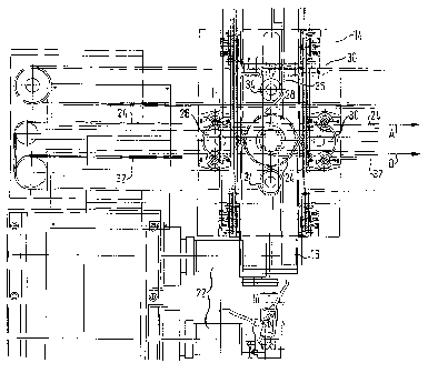
Referring now to Fig. 2 there is illustrated the slide 14 in section showing
how the
belts are guided in conjunction with the transfer device in accordance with
the
invention. A first belt 24 is guided via a first guide roller 26 and
furthermore on the
underside of a first drive wheel 28. At the right-hand side of the drive wheel
28 there
is provided a further guide roller 30 so that the belt is reliably guided
passed the
underside of the first drive wheel 28 whilst reliably engaging the teeth of
this wheel.
To the right of the guide roller 30 is the first belt 24 which is at the same
level as on
the left of the first guide roller 26, namely at an "upper" level.
By contrast, a second belt 32 is provided at a "lower" level and is guided
from the
underside of a further guide roller, which is shown in Fig. 2 as located
"downstream"
of the guide roller 26 as shown, to the upper side of a second drive wheel
which is
likewise located "downstream" of the drive wheel 28 as shown. At this upper
side the
second belt 32 engages the second drive wheel by means of the teeth. A further
guide
roller on the right ensures that the second belt 32 is guided in turn by the
upper side of
the second drive wheel to the "lower" level. It is, of course, just as
conceivable that
each of the traction means is not guided by the corresponding drive wheel, as
provided for in the preferred embodiment, but simply by engaging each drive
wheel
at opposite sides and being maintained engaged by suitable means at this
location.
It is this opposing wrap of two drive wheels as described that achieves
horizontal
shifting of the slide 14. As regards the belts 24 and 32 it is to be noted
that these are
configured endless so that they can be driven in both directions by the drive
motor 22
assigned in each case. When the belt 24 is driven such that at the location as
indicated
by the arrow A in Fig. 2 it is moved in the direction of the arrow A and the
belt 32 is
driven at the location as indicated by the arrow B in Fig. 2 is likewise moved
in this
direction, then the two drive wheels mounted on a common shaft or spindle will
not
move since the two movements of the belts 24, 32 cancel each other out in this
respect. Instead, the slide 14 is moved as a whole in the direction of the
arrows A, B,
with each of the two drive motors 22 needs to furnish half of the drive moment
which
is a major advantage in dimensioning the two motors.
= CA 02424071 2003-03-31
9
When, instead, the plunger 16 is to be moved in the vertical direction
relative to the
slide 14, the two belts are driven in different directions such that the two
drive wheels
rotate relative to the slide 14, and a third drive wheel provided on a common
shaft
with the other two drive wheels, is likewise rotated so that the plunger can
be moved.
When, for example, the "lower" belt 32 wrapped at the top is moved such that
it is
moved at the observed location in the direction of the arrow B whilst the
upper belt
24 wrapped "at the bottom" is moved opposite to the direction of the arrow A,
then
the two drive wheels rotate in all clockwise. In this case, it is to be noted
that it is
particularly when employing contour control that each of the drive motors 22
can be
driven so that the movement of the two belts is exactly opposing each other so
that
the slide 14 is stationary and only the shaft with the three drive wheels in
the slide 14
rotates. As indicated in Fig. 2 a further cogged belt 36 is guided by two
guide rollers
34 laterally via the third drive wheel (not shown) such that the cogged belt
36 is
shifted by a rotation of the drive wheel and since the ends of the cogged belt
are
fixedly attached to the plunger 16 the plunger is moved correspondingly. More
particularly, the plunger is moved upwards on clockwise rotation of the drive
wheel,
it being moved downwards when the drive wheel is driven counter-clockwise by
the
first belt 24 being moved in the direction of the arrow A and the second belt
32
opposite to the arrow B.
Regarding Fig. 2, it must be noted that a clincher 38 of a belt is shown by
which the
two ends of the belt are joined together to make for an endless cogged belt.
Since this
clincher is relatively bulky and thus tends to oscillate especially on longish
free
sections, it is preferred that a guiding means is provided in which at least
one section
of the clincher is guided such that it has no movement in the vertical
direction and
thus prevents oscillations. It is furthermore to be noted that the movements
of the two
belts between the modes of operation as described above, shifting the slide,
on the
one hand, and moving the plunger, on the other, can be suitably combined. When
the
two belts are driven up to a point at which the plunger is to be lowered, in
the
direction of the arrow A and B respectively, and subsequently the two belts
are driven
opposingly to move the plunger, the gripper provided on the plunger is moved
to a
certain extent forming a right angle, namely firstly horizontally and after
halting
thereof, vertically. It is basically possible that the vertical movement can
be
commenced earlier, as long as no obstacle stands in the way with which the
gripper
could collide, so that the right angle as described is shorted or rounded to
some
extent. There is no problem in attaining this by suitably controlling the two
motors in
CA 02424071 2003-03-31
combining the movements needed for downwards motion with those for shifting
section-wise.
Referring now to Fig. 3 there is illustrated how the three drive wheels 28, 40
and 42
are fixedly attached to a common shaft 44 mounted rotatably in the slide 14.
Evident
on the sides of the slide 14 are the trapezoidal guiding means 46 at which the
slide is
guided in the embodiment as shown via suitably configured rollers 48. It is
clearly
evident from Fig. 3 that the three drive wheels 28, 40 and 42 are arranged
juxtaposed
so that the opposing guidance of the belts 24 and 32 as indicated in Fig. 3
results in
no mutual effect. Provided between the two drive wheels 28, 42 in the
embodiment as
shown is the third drive wheel 40 which rotates with the shaft 44 which is
then driven
to rotate when the two drive wheels 28, 42 are actuated opposingly. On
rotation, the
third drive wheel 40 imparts a vertical movement to the plunger 16 via a belt
36
guided to some extent laterally (cf. Fig. 2).
Referring now to Fig. 4, there is illustrated an alternative embodiment for
imparting
the movement to the plunger 16. The two drive wheels 28, 42 are provided
juxtaposed to a certain extent within the slide 14. The common shaft 44
rotatively
mounted in the slide 14 protrudes from the slide where the third drive wheel
40 is
provided. This third drive wheel 40 engages a gear rack 50 fixedly provided on
the
plunger 16 which is guided via suitable trapezoidal guiding means in rollers
52
provided rotatably on the plunger 16. In this embodiment too, the transfer
device can
be configured simply and compactly to achieve movement of the plunger 16 and
more particularly the gripper provided thereon in two directions perpendicular
to each
other. It is furthermore to be noted that as evident from the illustration in
Fig. 4 the
plunger 16 is moved perpendicular to the plane of the drawing and the slide 14
is
shifted on the associated guiding means as shown in Fig. 4 from top to bottom.