Note : Les descriptions sont présentées dans la langue officielle dans laquelle elles ont été soumises.
CA 02424412 2003-04-02
9325-62 (159391) PHIP'323105
FLEXTBLE POUCH HAVING SYSTEM
FOR M1XING TWO COMPONENTS
Field of the Invention
[ 0001 ] The present invention relates to flexible pouches and, more
particularly, the present
invention relates to flexible pouches that provide chambers for separate
storage of liquid
components or liquid and dry components
Background of the Invention
[0002] Flexible pouches are used for packaging a wide variety of consumer
products.
Many consumer products, such as hair coloring, cleaning and pharmaceutical
products, for
example, include components that reduire separate storage for mixing by the
consumer prior
to use. The use of individual packaging for the separate components, however,
requires that a
third container be used to package the product for handling and sale of the
product to the
ultimate consumer of the product. The additional packaging is used only for
containing the
individual packages and becomes disposable following removal of the individual
component
packages. The use of individual packaging for the separate components further
necessitates
that a vessel, such as a bowl, be used to nux the components. The use of a
separate vessel for
mixing, however, creates the potential for spillage and requires that the
vessel be cleaned
following use of the product.
[0003] Flexible pouches having multiple chambers for separate storage of
product
components are known. The inclusion of multiple chambers in the single package
allows for
handling of the product and delivery to an end user without the need for
additional packaging.
The reduction in the packaging required, therefore, serves to linut waste
generated by the
product. For use of the product, however, it is still required that the
components be removed
from the package into a separate vessel for mixing prior to use.
CA 02424412 2003-04-02
9325-62 (159391) PHIP'323105
-2-
[0004] U.S. Pat. No. 4,608,043 to Larkin discloses a multiple chambered
flexible package
in which a separating barrier between two chambers includes a weakened
section. Upon
application of sufficient pressure to the contained substance of one the
chambers, the
weakened portion is designed to rupture to provide for mixing communication
between the
two chambers. Following mixing of the components, the product is delivered
from the
package through an access port provided at an end of the package. The weakened
portion of
the barrier wall, however, may be pressurized inadvertently during shipping
and handling of
the flexible package for example. Such premature rupturing of the barrier
would likely result
in waste of a product having components that require separation until
immediately prior to use
of the product.
Summary of the Invention
[0005] The present invention provides a flexible pouch having first and second
panels that
are secured together along opposite sides of the pouch. The panels define a
plurality of
chambers for separate storage of multiple components by the pouch.
[0006] The pouch further includes a titment secured to the panels at an end of
the pouch.
The fitment includes a bore having upper and lower portions. The fitment
further includes a
plurality of passages each extending from the lower portion of the bore to the
chambers.
[0007] The pouch also includes a closure having a first portion sized and
dimensioned for
close interfit with the lower portion of the plug to prevent fluid transfer
between the chambers.
The first and second closure portions being connected by a frangible
connection.
X0008] The frangible connection between the first and second closure portions
providing
for disengagement of the first closure portion from the bore for separation of
the first closure
portion from the second closure portion Engagement of the second closure
portion with the
upper portion of the bore providing for nuxing of the components within the
pouch.
CA 02424412 2003-04-02
9325-62 (19391) PHIP~323105
_3-
Brief Description of the Drawings
[0009] For the purpose of illustrating the invention, there is shown in the
drawings a form
that is presently preferred; it being understood, however, that this invention
is not limited to
the precise arrangements and instrumentalities shown.
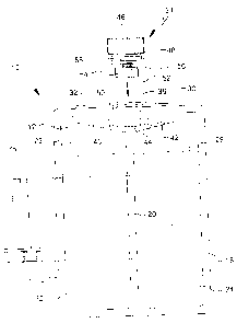
(0010] Figure 1 is a front view of a pouch according to the present invention
having a
system for mixing multiple components contained in the pouch;
[0011] Figure 2 is a perspective view of the fitment and closure member of the
pouch of
Figure 1;
[0012] Figure 3 is a sectional view taken along, the lines 3-3 of Figure 2;
[0013] Figure 4 is a side view, partly in section, showing the closure member
of Figure 2
engaging the fitment prior to removal of the plug portion of the closure
member;
[0014] Figure 5 is a side view, partly in section, showing the closure member
of Figure 2
engaging the fitment after removal of the plug portion;
[0015] Figure 6 is a perspective view of the pouch of Figure I shown being
used to mix
components of separate compartments through the fitment;
(0016] Figure 7 is rear view of the pouch of Figure 1 showing a dispensing
attachment
secured to the rear of the pouch; and
[0017] Figure 8 is a side view, partly in section, of a stand-up pouch
according to the
present invention.
Detailed Description of the Preferred Embodiments
[0018] Referl-ing to the drawings, where like numerals identify like elements,
there is
illustrated in Figure 1 a flexible pouch 10 according to the present
invention. The pouch 10
includes a front panel 12 and an opposite rear panel 14 (Fig. 6) secured
together along
opposite sides 16, 18, preferably by heat sealing;. The front and rear panels
12, 14 are also
CA 02424412 2003-04-02
9325-62(159391) PHIP\323105
-4-
heat sealed to each other along an intermediate line 20 extending parallel to
the sides 16, 18 to
define first and second chambers 22, 24. 'fhe charrihers 22, 24 provide for
separate storage of
product components until the components are mixed in the manner to be
described below.
Pouch 10 is shown in Figure 1 containing liquids 26, 28, respectively, in
chambers 22, 24. A
hair coloring formulation is an example of a product having multiple liquid
components that
are separately packaged until nuxed by the consumer prior to use of the
product. Alternatively,
the pouch 10 could provide separate storage for a product having liquid and
dry components,
such as a pharmaceutical formulation for example.
[0019] A fitment 30 is located at an end of the pouch 10 to provide for
closure of the
separate chambers 22, 24. The front and rear panels 12, 14 of the pouch 10 are
secured to
side surfaces 32 of the fitment 30, preferably by heat sealing. The front and
rear panels 12, 14
may also be secured to each other adjacent a lower edge of the fitment 30. A
closure member
34 is engageable with a bore 36 of the fitment 30. The closure member 34, in
the manner to
be described, provides for separation of the liquids 26, 28 until mixing of
tile liquids is desired.
(0020] A nozzled attachment 38 is engageable with the bore 36 of the fitment
30 to
provide for dispensing of the contained product after the liquids 26, 28 have
been mixed
within the pouch 10. The nozzled attachment 38 is preferably contained in a
suitable
enclosure, such as a plastic container 39 (Fig. 7). The container 39 is
secured to the rear panel
14 of the pouch I 0, as shown, preferably by an adhesive material.
[0021 ] Referring to Figures 2-5, the construction and operation of the
fitment 30 and the
closure member 34 is illustrated in greater detail. As shown in Figure 2, the
fitment 30 has a
thickness that is maximum in a nuddle pol-tion such that the fitment 30 is
generally canoe-
shaped. The fitment 30 includes passages 40, 42 extending in opposite
directions fi~om a
lower portion 44 of the bore 36 to the lcswer edge of the fitment 30. The
passages 40, 42 link
the bore 36 to the chambers 22, 24 to provide for fluid transfer between the
chambers 22, 24
through the ftment 30.
(0022] The closure member 34 includes a cap 46 having an externally threaded
pol-tion 48
engageable with an internally threaded upper portion 50 of the bore 36. The
closure member
CA 02424412 2003-04-02
9325-62 ( 159391 j PHIP~323105
-S-
34 further includes a plug 52 attached to the cap 46. A lower portion 54 of
the plug 52 is
dimensioned for close interfit with the lower portion 44 of the bore 36. The
engagement
between the plug 52 and the bore 36 functions to seal the passages 40, 42
thereby preventing
transfer of fluids between the chambers 22, 24.
[0023] The plug 52, preferably made from a soft rubber material, is adhered or
welded to
the cap 46, preferably made from a molded plastic material. As shown in Figure
1, the plug 52
includes a reduced diameter portion 56 with respect to the lower portion 54.
The reduced
diameter poI-tion 56 functions as a fi~angible stem that is adapted to be
broken by a user to
provide for mixing of components between the chambers 22, 24 in the manner
described
below. The reduced diameter stem 56 includes a score line 58 to facilitate
separation of the
lower portion S4 of the plug 52 from the cap 46. The reduced diameter portion
56, however,
should possess sufficient strength to provide for initial engagement of the
plug 52 with the
lower portion 44 of bore 36 to seal the chambers 22, 24 as the cap 46 engages
the upper
portion 50 of the bore 36.
[0024] The pouch 10 is designed for mixing and delivery of separate components
in the
following manner. As shown in Figure 1, the liquid components 26, 28 are
proportioned with
respect to the chambers 22, 24 such that neither of the chambers is completely
filled. The
space provided in the chambers 22, 24 in this manner facilitates transfer of
fluid between the
chambers 26, 28 to provide for mixing i>f the components 26, 28.
[0025] To provide for mixing of the components 26, 28 by fluid transfer
through the
fitment 30, a user disengages the closure member 34 form the fitment 30 by
unthreading the
cap 46 from the upper portion 5U of the bore 36. The user then separates the
plug 52 from the
cap 46 by twisting the lower portion 54 of the plug 52 with respect to the cap
46. The
twisting of the lower portion 54 severs the lower poI-tion S4 from the cap 46
along the score
line 58. The cap 46 is then threaded into the bore 36 without the plug 52. The
engagement of
the cap 46 with the bore 36, without the plug 52, provides a condition in
which the chambers
22, 24 are in fluid communication through the bore 36 while the bore is closed
by the cap 46.
CA 02424412 2003-04-02
9325-62(159391) PHIP~323105
_6_
[0026] To mix the components 26, 28, a user applies pressure to the chambers
22, 24, as
shown in Figure 6, in an alternating fashion such that liquid is transferred
back and forth
between the chambers 22, 24 through the fitment 30. The fluid transfer between
the chambers
22, 24 mixes the liquid components 26, 28. To facilitate mixing, the liquids
26, 28 desirably
possess sufficiently low viscosity such that the liquids easily pass between
the chambers 22 24
through the passages 40, 42 of the fitment 30. One of the front and rear
panels 12, 14 may be
made from a transparent material to facilitate visual examination of the
components 26, 28
within chambers 22, 24 for determining when sufficient mixing of the
components 26, 28 has
occurred.
(0027] The product is discharged from the pouch 10 following sufficient mixing
of the
components 26, 28 as follows. The closure member 34 is disengaged from the
fitment 30 to
provide an exit path for the mixed components 26, 28 from the pouch 10 via the
passages 40,
42 and the bore 36. The pouch 10 may then be inverted and pressure applied to
the chambers
22, 24 by a user for discharge of the mixed components 26, 28. To facilitate
discharge of the
mixed components 26, 28 in a controlled manner, a user removes the nozzled
attachment 38
from the container 38 secured to the rear panel 14 and threads the attachment
38 into the
upper portion 50 of bore 36.
[0028) Referring to Figure 8, there is shown a pouch 60 according to a second
embodiment of the present invention. The pouch 60 includes first and second
panels 62, 64
secured to each other along opposite sides of the panels, in a similar fashion
to the front and
rear panels 12, 14 of pouch 10. The first and second panels 62. 64 are also
secured to first
and second surfaces 68, 70, respectively. of a fitment 66
[0029] The pouch 60 further includes a third panel 72 secured to the first and
second
panels 62, 64. The connection of the third panel 72 to the first and second
panels 62, 64
provides for self support of the pouch 60. As shown, the third panel 72
extends upwardly
between the first and second panels 62, 64 to a central fold 74 that is
secured to a lower
pardon of the fitment 66 between the first and second panels 62, 64. The
bottom of the
fitment 66 differs from the generally pointed bottom of fitment 30 and is,
instead, rounded to
facilitate the securing of the central fold 74 of third panel 72 to the
fitment 66. The
CA 02424412 2003-04-02
9325-62 (159391) PHIP~23105
_7_
connection of the third panel 72 to the pouch 60 in this manner divides the
interior of the
pouch 60 into first and second chambers 76, 78. The chambers 76, 78 differ
from the
chambers 22, 24 of pouch 10 because the ch<~mbers 76, 78 are located forwardly
and
realwardly of each other rather than in a side-by-side fashion as was the case
with chambers
22, 24. The chambers 76, 78 are shown containing liquid components 80, 82. As
was the
case with pouch 60, however, the chambers 76, 78 of pouch 60 could
alternatively contain a
product such as a pharmaceutical product having a liquid and a dry component.
[0030) The pouch 60 includes a closure member 34 received in a bore 36 of the
fitment
66. The closure member 34, similar to the closure member 34 of pouch 10,
includes a cap 46
threadedly engaged to the bore 36 and a removable plug 52 for sealing a lower
portion of the
bore 36.
(0031) The fitment 66 includes first and second passages 84, 86 extending from
the bore
36. The first and second passages 84, 86 extend in opposite directions to
communicate with
the first and second chambers 76, 78, respectively. The orientation of the
passages 84, 86 of
pouch 60 is generally perpendicular to that of passages 40, 42 to provide for
communication
with the forwardly and realvardly located chambers 76, 78. Otherwise the
passages 84, 86
function similarly to passages 40, 42 to provide for fluid communication
between the chambers
76, 78 through the bore 36 following removal of plug 52 from the closure
member 34. To
transfer fluid between the chambers 76, 78 of pouch 60, a user can apply
pressure to the
chambers 76, 78 through the bottom of the pouch 60.
[0032) While the present invention has been described in connection with the
prefel~-ed
embodiments of the various figures, it is to be understood that other similar
embodiments may
be used or modifications and additions may be made to the described
embodiments for
performing the same function of the present invention without deviating
therefi~om. Therefore,
the present invention should not be limited to any single embodiment, but
rather should be
construed in breadth and scope in accordance with the recitation of the
appended claims.