Sélection de la langue

Search

Sommaire du brevet 2425394 

Énoncé de désistement de responsabilité concernant l'information provenant de tiers

Une partie des informations de ce site Web a été fournie par des sources externes. Le gouvernement du Canada n'assume aucune responsabilité concernant la précision, l'actualité ou la fiabilité des informations fournies par les sources externes. Les utilisateurs qui désirent employer cette information devraient consulter directement la source des informations. Le contenu fourni par les sources externes n'est pas assujetti aux exigences sur les langues officielles, la protection des renseignements personnels et l'accessibilité.

Disponibilité de l'Abrégé et des Revendications

L'apparition de différences dans le texte et l'image des Revendications et de l'Abrégé dépend du moment auquel le document est publié. Les textes des Revendications et de l'Abrégé sont affichés :

  • lorsque la demande peut être examinée par le public;
  • lorsque le brevet est émis (délivrance).
(12) Demande de brevet: (11) CA 2425394
(54) Titre français: ORGANE SEPARATEUR DANS UN DISPOSITIF DE COLLAGE DE BLOCS EN BOIS
(54) Titre anglais: SEPARATING MECHANISM IN AN APPARATUS FOR THE GLUING OF WOOD BLOCKS
Statut: Réputée abandonnée et au-delà du délai pour le rétablissement - en attente de la réponse à l’avis de communication rejetée
Données bibliographiques
(51) Classification internationale des brevets (CIB):
  • B27G 11/00 (2006.01)
  • B27M 01/08 (2006.01)
(72) Inventeurs :
  • KALLIO, PENTTI (Finlande)
(73) Titulaires :
  • JARME OY
(71) Demandeurs :
  • JARME OY (Finlande)
(74) Agent: GOWLING WLG (CANADA) LLP
(74) Co-agent:
(45) Délivré:
(22) Date de dépôt: 2003-04-14
(41) Mise à la disponibilité du public: 2003-10-15
Licence disponible: S.O.
Cédé au domaine public: S.O.
(25) Langue des documents déposés: Anglais

Traité de coopération en matière de brevets (PCT): Non

(30) Données de priorité de la demande:
Numéro de la demande Pays / territoire Date
20020725 (Finlande) 2002-04-15

Abrégés

Abrégé anglais


A separating mechanism in a gluing apparatus for the glu-
ing of elongated wood blocks (1), said gluing apparatus
comprising an adhesive application unit for the application
of adhesive at least to one of the surfaces (1a, 1b) to be
glued and a pressing mechanism (11, 12) for pressing to-
gether the surfaces to be glued, and said separating
mechanism comprising a frame part and separating ele-
ments for keeping the wood blocks (1) clear of each other
before the pressing. The separating mechanism of the
invention comprises a vertical frame part (3) provided with
supporters (4) functioning as separating elements, ar
ranged one above the other at least on one side of the
frame part, on which. supporters the wood blocks can be
arranged, and which frame part can be moved in vertical
and horizontal directives by an operating mechanism, and
a stopper arrangement far stopping the wood blocks (1)
and arranging them so that the surfaces to be glued are
set against each other in order to be pressed together.

Revendications

Note : Les revendications sont présentées dans la langue officielle dans laquelle elles ont été soumises.


5
CLAIMS
1. Separating mechanism in a gluing apparatus for the gluing of
elongated wood blocks (1), said gluing apparatus comprising an adhesive appli-
cation unit for the application of adhesive at least to one of the surfaces
(1a, 1b)
to be glued and a pressing mechanism (11, 12) for pressing together the sur-
faces to be glued, and
said separating mechanism comprising a frame part and separating
elements for keeping the wood blocks (1) clear of each other before the press-
ing,
characterized in that the separating mechanism com-
prises;
a vertical frame part (3) provided with supporters (4) functioning as
separating elements, arranged one above the other at least on one side of the
frame part, on which supporters the wood blocks can be arranged, and which
frame part can be moved in vertical and horizontal directions by an operating
mechanism, and
a stopper arrangement for stopping the wood blocks (1) and arrang-
ing them so that the surfaces to be glued are set against each other in order
to
be pressed together.
2. Separating mechanism according to claim 1 in a gluing appara-
tus provided with a conveyor (2) for conveying the wood blocks, charac-
terized in that the mechanism comprises a pusher system (5) for push-
ing wood blocks from the conveyor onto the supporters.
3. Mechanism according to claim 1 provided with a conveyor (2) for
conveying the wood blocks, characterized in that the conveyor and
the supporters are placed next to each other when wood blocks are being ar-
ranged from the conveyor onto the supporters, allowing the wood blocks to be
transferred to the supporters by means of the conveyor.
4. Separating mechanism according to claim 1, character-
ized in that supporters (4) are arranged on either side of the frame part,
5. Separating mechanism according to claim 2, character-
ized in that, in the stopper arrangement, each pusher part (5) comprises a
vertical bar-like pusher element (8) and that a back stop (7) is provided in
con-
nection with each pusher, against which back stop the pusher presses the wood
blocks to stop them and to arrange them so that the surfaces to be glued are
set against each other.

6
6. Separating mechanism according to claim 6, character-
ized in that, to allow shaped products to be glued, the pusher part (8) has
at least one projection/notch (9) and its back stop at least one corresponding
notch/projection (11).
7. Separating mechanism according to claim 1, character-
ized in that the separating mechanism comprises a planar support (12), on
which the wood blocks are arranged as a bundle (13) for the pressing
operation.
8. Separating mechanism according to claim 7, character-
ized in that the planar support (12) is fitted at least partly outside the
press-
ing mechanism as seen from the supply direction so that the wood blocks are
arranged as a bundle (13) for the pressing operation before the pressing
mechanism.

Description

Note : Les descriptions sont présentées dans la langue officielle dans laquelle elles ont été soumises.

CA 02425394 2003-04-14
1
SEPARATING MECHANISM IN AN APPARATUS FOR THE GLUING OF
WOOD BLOCKS
The present invention relates to a separating mechanism as de-
s fined in the preamble of claim 1 in a gluing apparatus for the gluing of
elongated
wood blocks, said apparatus comprising a unit for the application of adhesive
and a pressing mechanism for pressing the wood blocks together.
For example in gluing apparatus used in the manufacture of glued
timber beams, adhesive is applied by means of glue application device to one
of
~o the two surfaces to be placed against each other, whereupon the pieces to
be
glued together are subjected to compression in a pressing device and held un-
der compression until the adhesive has dried sufficiently. The drying times
are
relatively long, and due to the long drying times, relatively large pressing
de-
vices are needed.
is Patent spec~cation FI 97959 discloses an apparatus for joining
wood blocks, such as glued laminated beams and laminated lags, wherein ad-
hesive is applied to one surface of the wood blocks and the wood blocks are
moved in a horizontal plane and heated from the opposite side by means of an
IR radiator placed above them, whereupon the wood blocks are stacked so that
2o the glued surface and the heated surface of adjacent blocks are placed
against
each other and pressed together by a pressing device. Adhesive is applied only
to the block forming the lower surface while the block forming the upper
surface
is only heated. The wood blocks between these are treated in both ways.
In the apparatus disclosed in the specification in question, planed
25 blocks carried on a longitudinal conveyor through a glue application device
are
turned by means of a manipulator so that the glued surface faces downwards
and then placed on a transverse conveyor, which supports it on nodules to
avoid soiling the glue. The block is transferred transversely under the IR
radia
tor, whereby the surface of the adhesive layer is heated to a desired tempera
3o ture. After this, the block is turned and placed on a comb conveyor which
sup
ports l t on c ombs functioning a s s eparating a lements, I eaving a n a it g
op b e
tween the blocks to prevent re8ction of the adhesive. The blocks carried by
the
comb conveyor are set one upon the other and, when the stack thus formed has
reach the desired size, it is moved to the pressing device either by means of
35 manipulators one at a time or as a bundle.
The adhesive may also consist of a Twin-component glue having a
resin component and a hardening component, in which case the resin compo-

CA 02425394 2003-04-14
2
vent and the hardening component are applied separately, the blocks being
joined together in a pressing device by heating, In this case, the resin compo-
nent is applied to one of the surfaces and the hardening component to the
other, as described e.g. in published patent application FI X7969.
The object of the present invention is to achieve a new type of
separating mechanism that allows mare efficient gluing together of wood
blocks.
The separating mechanism of the invention comprises a vertical frame part pro-
vided with supporters placed one above the other, upon which the wood blocks
are arranged one above the other spaced from each other. In addition, the ap-
~o paratus comprises a stopper arrangement, by means of which the wood blocks
are stopped so that they wilt fall one upon the other before being glued
together
in a pressing device or before it, and an actuator, by means of which the
frame
part can be raisedllowered and moved into the pressing device.
(n an embodiment of the invention, the apparatus comprises a
is pusher, by means of which the wood blocks are pushed onto the supporters.
in another embodiment of the invention, the pusher and its stopping
piece are provided with a projection and a notch corresponding to each other
to
allow shaped compregnated wood blocks to be produced.
The features of the separating mechanism of the invention are pre-
20 sented in detail in the claims below.
The solution of the invention provides many advantages. The sepa-
rating mechanism makes it possible to reduce the joining time a s the wood
blocks can be placed one above the other on supporters and dropped onto one
another relatively quickly. In addition, the apparatus is simple and occupies
rela-
2s tively little space due to its upright structure. If the stopping
arrangement is dis-
posed before the pressing device, the dimensions of the pressing device can be
reduced because a complete bundle can be fed into the mouth of the pressing
device.
In the following, the invention will be described in detail by the aid of
3o an example with reference to the attached drawing, wherein
Fig. 1 presents a separating mechanism according to the invention,
Fig. z presents a second separating mechanism according to the
invention,
Fig. 3 presents a third separating mechanism according to the in-
35 vention, and
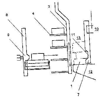
Fig. 4 presents an embodiment of the pusher and its stopping de-
vice, which makes it possible to produce shaped pieces.

CA 02425394 2003-04-14
3
The separating mechanism of the invention is used to produce e.g.
laminated logs from laminae. The planed laminae 1 are conveyed an a longitu-
dinal conveyor 2 into an IR radiation heater, where bath joint surtaces 1 a, 1
b of
the laminae are heated. After that, the laminae 1 are passed into a glue
applica-
tor, where adhesive is applied to one 1a of the joint surfaces. Next, the
laminae
are stacked and pressed together in a vertical pressing device to form a lami-
noted log.
Before the pressing device, the laminae 1 are arranged in the sepa
rating mechanism, which maintains an air gap between the laminae 1 to prevent
~o premature reaction of the adhesive.
The separating mechanism presented In Fig. 1 comprises a verticai
main beam 8 and,~arranged on one side of it, horizontal comb-like supporters
placed one above the other, consisting of round bars 4 or equivalent placed at
certain distances. The frame 3 can be raisedllowered and moved in a horizontal
s5 plane by means of its actuating mechanism.
The apparatus works as follows: Each lamina 1 brought by the lon-
gitudinal conveyor 2 to a position alongside the separating mechanism is
pushed by means of pushers 5 disposed consecutively and provided with a
pushing element G at their ends ante the supporter 4 currently located at the
20 level of the longitudinal conveyor 2. Once a sufficient number of laminae
have
been thus loaded, the frame 3 with the supporters 4 is moved to a position
next
to a stopping device (not shown) comprised in the pressing device, which stops
the laminae 1 while the frame part continues moving, thus causing the laminae
to fall down one upon the other to be pressed together.
z5 In the apparatus presented in Fig. 2, the conveyor Z and the sup-
porters 4 are aligned with each other. In this case, to move the laminae from
the
conveyor onto the supporters, the conveyor, which is disposed before the sepa-
rating mechanism, pushes the lamina 1 onto the supporter 4 next to it, where-
upon the supporters are raised so that the next lamina will be moved onto the
3o next supporter below, and so on, until a sufficient number of laminae have
been
arranged on the supporters for the pressing operation.
The a pparatus p resented i n F ig. 3 h as supporters 4 a rranged o n
either side of the frame part 3, in which case the separating mechanism can be
used even with pressing devices comprising two pressing units placed side by
35 side. In this case, the frame part is moved laterally (arrow) ss necessary,
de
pending on which one of the pressing units is being loaded with laminae.

CA 02425394 2003-04-14
4
Fig. 4 presents an embodiment In which the stopping devices con-
sist of pushers 5 and their back stops 7. The pushers 5 have a vertical
pushing
bar 8. The bank stop 7 is likewise a vertical bar. >"lfter the laminae 1 have
been
stacked one above the other on the supporters ~4, the pushers 5 are moved be-
s tween the bars to push the laminae 1 against the back stops 7, the wood
blocks
being thereby stopped between the pushers 5 and the back stops 7 while the
frame part 3 is moved further past the pressing device. After that, the
pressure
between the pushers 5 and the back stops 7 is reduced, allowing the laminae 1
to fall down one upon the other to form a bundle 13 on a support 12, ready to
be
to pressed by means of the top ram 10 of the pressing device.
The apparatus presented in Fig. 4 can also be used to create
shaped products, such as thresholds ar the Pike. In this case, the push bar 8
of
the pusher 5 has a projection 9 at about the middle of It and similarly the
back
stop 7 has a corresponding notch 11 at the desired poshion, so that the bundle
15 13 piled on the support 12 has a staggering where one of the laminae 1 may
be
laid deeper than the others to produce a desired shape as illustrated in Fig.
4,
The bundles 13 may be piled onto the support 12 either in the
pressing device or alternatively before the pressing device. If the bundles 13
are
assembled before the pressing device, then the support 12 extends outside the
2o pressing device as seen from the supply direction at least through a
distance
required by the length of the wood blocks.
It is obvious to the person skilled in the art that the invention is not
limited to the embodiment examples described above, but that they may be var-
ied within the scope of the claims presented below.

Dessin représentatif
Une figure unique qui représente un dessin illustrant l'invention.
États administratifs

2024-08-01 : Dans le cadre de la transition vers les Brevets de nouvelle génération (BNG), la base de données sur les brevets canadiens (BDBC) contient désormais un Historique d'événement plus détaillé, qui reproduit le Journal des événements de notre nouvelle solution interne.

Veuillez noter que les événements débutant par « Inactive : » se réfèrent à des événements qui ne sont plus utilisés dans notre nouvelle solution interne.

Pour une meilleure compréhension de l'état de la demande ou brevet qui figure sur cette page, la rubrique Mise en garde , et les descriptions de Brevet , Historique d'événement , Taxes périodiques et Historique des paiements devraient être consultées.

Historique d'événement

Description Date
Le délai pour l'annulation est expiré 2009-04-14
Demande non rétablie avant l'échéance 2009-04-14
Inactive : Abandon.-RE+surtaxe impayées-Corr envoyée 2008-04-14
Réputée abandonnée - omission de répondre à un avis sur les taxes pour le maintien en état 2008-04-14
Demande publiée (accessible au public) 2003-10-15
Inactive : Page couverture publiée 2003-10-14
Inactive : CIB en 1re position 2003-07-24
Inactive : CIB attribuée 2003-07-24
Lettre envoyée 2003-07-02
Inactive : Transfert individuel 2003-05-26
Inactive : Lettre de courtoisie - Preuve 2003-05-13
Demande reçue - nationale ordinaire 2003-05-12
Inactive : Certificat de dépôt - Sans RE (Anglais) 2003-05-12

Historique d'abandonnement

Date d'abandonnement Raison Date de rétablissement
2008-04-14

Taxes périodiques

Le dernier paiement a été reçu le 2007-02-22

Avis : Si le paiement en totalité n'a pas été reçu au plus tard à la date indiquée, une taxe supplémentaire peut être imposée, soit une des taxes suivantes :

  • taxe de rétablissement ;
  • taxe pour paiement en souffrance ; ou
  • taxe additionnelle pour le renversement d'une péremption réputée.

Les taxes sur les brevets sont ajustées au 1er janvier de chaque année. Les montants ci-dessus sont les montants actuels s'ils sont reçus au plus tard le 31 décembre de l'année en cours.
Veuillez vous référer à la page web des taxes sur les brevets de l'OPIC pour voir tous les montants actuels des taxes.

Historique des taxes

Type de taxes Anniversaire Échéance Date payée
Taxe pour le dépôt - générale 2003-04-14
Enregistrement d'un document 2003-05-26
TM (demande, 2e anniv.) - générale 02 2005-04-14 2005-02-07
TM (demande, 3e anniv.) - générale 03 2006-04-14 2006-03-06
TM (demande, 4e anniv.) - générale 04 2007-04-16 2007-02-22
Titulaires au dossier

Les titulaires actuels et antérieures au dossier sont affichés en ordre alphabétique.

Titulaires actuels au dossier
JARME OY
Titulaires antérieures au dossier
PENTTI KALLIO
Les propriétaires antérieurs qui ne figurent pas dans la liste des « Propriétaires au dossier » apparaîtront dans d'autres documents au dossier.
Documents

Pour visionner les fichiers sélectionnés, entrer le code reCAPTCHA :


Pour visualiser une image, cliquer sur un lien dans la colonne description du document (Temporairement non-disponible). Pour télécharger l'image (les images), cliquer l'une ou plusieurs cases à cocher dans la première colonne et ensuite cliquer sur le bouton "Télécharger sélection en format PDF (archive Zip)" ou le bouton "Télécharger sélection (en un fichier PDF fusionné)".

Liste des documents de brevet publiés et non publiés sur la BDBC .

Si vous avez des difficultés à accéder au contenu, veuillez communiquer avec le Centre de services à la clientèle au 1-866-997-1936, ou envoyer un courriel au Centre de service à la clientèle de l'OPIC.

({010=Tous les documents, 020=Au moment du dépôt, 030=Au moment de la mise à la disponibilité du public, 040=À la délivrance, 050=Examen, 060=Correspondance reçue, 070=Divers, 080=Correspondance envoyée, 090=Paiement})


Description du
Document 
Date
(aaaa-mm-jj) 
Nombre de pages   Taille de l'image (Ko) 
Description 2003-04-13 4 195
Dessins 2003-04-13 2 25
Abrégé 2003-04-13 1 22
Revendications 2003-04-13 2 63
Dessin représentatif 2003-09-16 1 7
Certificat de dépôt (anglais) 2003-05-11 1 159
Courtoisie - Certificat d'enregistrement (document(s) connexe(s)) 2003-07-01 1 105
Rappel de taxe de maintien due 2004-12-14 1 110
Rappel - requête d'examen 2007-12-16 1 118
Courtoisie - Lettre d'abandon (taxe de maintien en état) 2008-06-08 1 173
Courtoisie - Lettre d'abandon (requête d'examen) 2008-08-03 1 165
Correspondance 2003-05-11 1 24
Taxes 2005-02-06 1 29
Taxes 2006-03-05 1 34
Taxes 2007-02-21 1 40