Note : Les descriptions sont présentées dans la langue officielle dans laquelle elles ont été soumises.
CA 02425622 2003-03-07
WO 02/19921 PCT/IE01/00116
SURGICAL STAPLING INSTRUMENT
The present invention relates to surgical stapling
instruments, and in particular to instruments for
performing a vascular anastomosis procedure.
The term "anastomosis" covers a variety of procedures
in which blood vessels such as veins and arteries, or
other tubular members, such as part of the colon,
intestines, stomach etc., are joined or reconnected.
These vessels may be joined in a variety of relative
orientations, including end-to-end and end-to-side and
side-to side.
Recent advances made in the field of microsurgery and
beating heart surgery have led to the development of
alternatives to conventional suturing processes for
joining vessels in order to accommodate the minute size
of the vessels and in particular towards achieving a
rapid anastomosis during beating heart (off-pump)
coronary artery bypass surgery.
An alternative to suturing is the use of surgical clips
which are applied along the junction between the
vessels or tissue portions which are to be joined, and
the clips perform a holding function similar to that of
sutures. Two such non.-penetrating clips are shown in
US Patent Nos. 4,586,503 and 4,733,664.
The former patent discloses a surgical micro clip
composed of plastically deformable metal or plastic
material having minimal spring back when crimped. The
clip has a pair of parallel curved legs joined by a
CA 02425622 2003-03-07
WO 02/19921 PCT/IE01/00116
2
bridge at one end and terminating in round tips at the
other end. The clip grips the edges of the averted
tissue and joins them by crimping the legs together.
The latter patent discloses a vascular surgical clip
comprising a plastically deformable body portion, a
tang for deforming the body, and the neck connecting
the tang to the body. The body is designed to deform
upon application to the tang of a predetermined tensile
force, and the neck is designed to break upon
application of a force in excess of the predetermined
force to the tang.
As described in the above patents, the non-penetrating
clips are applied over opposed edges of the vessels,
the edges being first averted, or turned outward, to
form flanges that are gripped between the jaws of the
clips. A disadvantage of the above non-penetrating
clip is the necessity to apply these clips to the
outside of the averted tissues. The anastomosed
vessels being repaired need to be returned to the
intended function as quickly as possible, particularly
where critical blood flow is involved.
The need therefore, exists for an instrument for
rapidly applying surgical staples from either within
the lumen or from outside the site of the anastomosis.
Accordingly, the present invention provides a surgical
stapling instrument for stapling edges of tissue to be
joined, the instrument comprising an elongated body
and, carried by the body, a rigid member having a
hooked end for penetrating the edges of tissue to be
CA 02425622 2003-03-07
WO 02/19921 PCT/IE01/00116
3
joined and stapling means for applying a staple to the
edges held by the hooked end of the rigid member.
The invention also provides a device which accomplishes
the same result with folds in tissue, i.e. rather than
stapling two edges of tissue, an unbroken area of
tissue may be folded and the folds stapled together in
the same manner.
Preferably the stapling means comprises means for
driving a staple longitudinally of the body against the
inside of the hooked end of the needle for deformation
of the staple into penetrating engagement with the
everted edges.
The present invention may be used to perform a variety
of vascular anastomosis including peripheral vascular
surgical anastomosis, arterial venous fistula formation
for dialysis, and coronary artery bypass anastomosis.
More particularly, the present invention may be used to
perform a coronary artery bypass anastomosis utilising
a number of approaches including an open-chest approach
(with and without cardiopulmonary bypass), a closed-
chest approach under direct viewing and/or indirect
thorascopic viewing (with and without cardiopulmonary
bypass) .
In an embodiment of the invention the instrument
includes an elongated body with a handle at one end
(herein referred to as the rear end) and which
terminates at the other (front) end in a vascular
staple delivery mechanism and a tissue grasping needle
having a sharp hooked end. The elongated body portion
CA 02425622 2003-03-07
WO 02/19921 PCT/IE01/00116
4
includes two manually slidable members, the first to
extend and retract the needle relative to the front end
of the body and the second to deliver a staple which is
deformed around an anvil on the inside of the hooked
end of the needle. The staple is advanced by a spring
biased pusher member coupled to the second slider.
Upon approximation of one of the tissue walls to be
anastoinosed by a suitable vascular forceps, the needle
is extended so that the sharp hooked end of the needle
is advanced free of the front end of the body so that,
by manipulation by the user, it can penetrate and hook
the tissue wall. When one tissue wall has been hooked,
the forceps are used to approximate the other tissue
wall which is then also hooked by the extended needle.
The needle is configured so that when the tissue wall
has been hooked it is inclined to slide back towards
the narrow hooked end. The width of the hooked end is
optimally equivalent to the combined wall thicknesses
of the tissue walls being anastomosed. The needle is
then retracted so that the hooked end grasping the
tissue walls engages the front end of the body for
stability during the subsequent staple delivery.
Once the tissue to be anastomosed has been grasped and
approximated against the front end of the body the
pusher member is advanced forwardly along a track in
which a staple from a stack of 20 or more is
positioned. The pusher member advances the staple
along the track until the staple legs engage the inside
edge of the hooked end of the needle. As the staple is
further advanced the legs are deformed inward and
toward each other by the anvil through the hole in the
CA 02425622 2003-03-07
WO 02/19921 PCT/IE01/00116
tissue walls created by the needle. Once the staple is
deployed the pusher member returns so that its front
end is positioned proximal to the staple stack.
5 The needle slider is then advanced so as to move the
needle and stapled tissue away from the front end of
the body to allow the needle to be un-hooked from the
stapled tissue.
In a further aspect the invention provides a method of
stapling the edges of tissue to be joined, comprising
the steps of:
a) penetrating the edges of tissue to be joined
with a rigid member having a hooked end; and
b) applying a staple to the edges held by the
hooked end of the rigid member.
The embodiment of the invention will now be described,
by way of example, with reference to the accompanying
drawings, in which:
Figs. 1A to 1C are, respectively, a side view, a top
plan view and an opposite side view of an instrument
for applying a surgical staple to a blood vessel during
a microsurgical anastomosis procedure;
Figs. 2A to 2C are longitudinal sectional views of the
instrument, similar to those of Figs. 1A to 1C, with
the needle extended in preparation for penetrating and
grasping the edges of tissue to be anastomosed;
CA 02425622 2003-03-07
WO 02/19921 PCT/IE01/00116
6
Figs. 3A to 3C are longitudinal sectional views of the
instrument, similar to those of Figs. 2A to 2C, with
the needle retracted after having penetrated and
grasped the edges of the tissue;
Figs. 4A to 4C are longitudinal sectional views of the
instrument, similar to those of Figs. 2A to 2C, showing
a staple driven forwardly into the hook of the needle
just prior to closing the staple onto the tissue;
Fig. 4D is an enlarged detailed view of the circled
part of Fig. 4C;
Figs. 5A to 5C are longitudinal sectional views of the
instrument, similar to those of Figs. 2A to 2C, just
after closure of the staple;
Fig. 5D is an enlarged detailed view of the circled
part of Fig. 5C;
Fig. 5E is an enlarged detailed view of the circled
part of Fig. 5D;
Fig. 5F is an enlarged cross-section taken on the line
A-A of Fig. 5D;
Figs. 6A to 6C are longitudinal sectional views of the
instrument, similar to those of Figs. 2A to 2C, with
the needle extended once again to release the stapled
tissue;
Fig. 6D is an enlarged detailed view of the circled
part of Fig. 6C;
CA 02425622 2003-03-07
WO 02/19921 PCT/IE01/00116
7
Fig. 7 is a schematic side view of the tip of the
instrument during the creation of a pleat in tissue;
and
Fig. 8 is a sectional side view of the pleat when
created by the instrument.
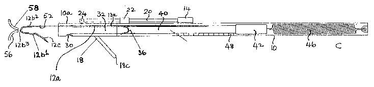
Referring now to the drawings, an instrument for
applying a surgical staple to a blood vessel during a
microsurgical anastomosis procedure comprises an
elongated hollow body 10 having a front "business" end
10a and a rear handle end 10b. A needle 12 is mounted
within the body 10 and has a straight body portion 12a
and a hooked front end 12b (hereinafter referred to
simply as a hook), the hook 12b terminating in a sharp
outwardly inclined tip 12c.
The body portion 12a of the needle is parallel to the
longitudinal axis of the body 10 and is slidable
longitudinally of the body 10 between an extended
position, Figs. 2 and 6, wherein the hook 12b is free
of the front end 10a of the body 10 and a retracted
position, Figs. 1, 3, 4 and 5, wherein the opposite
sides 12b1 and 12b2 of the hook are engaged with the
front end 10a of the body.
The needle 12 is actuated between its extended and
retracted positions by a thumb-operated slider 14
mounted on the outside of the body 10 and fixed to the
rear end of the needle portion 12a through a
longitudinal slot 16 (Fig. 1A) in the body. In its
extended position the needle 12 is able to penetrate
CA 02425622 2003-03-07
WO 02/19921 PCT/IE01/00116
8
and evert tissue walls to be anastomosed, while in its
retracted position the needle allows a staple to be
delivered to the everted tissue walls, as will be
described.
The slider 14 also operates a needle lock 18 via a push
rod 20 which is slidable longitudinally of the body 10
in a bearing 22. The needle lock comprises a U-shaped
member 18 which embraces the front end 10a of the body
10 and whose opposite arms 18a, 18b are pivoted to the
front end of the push rod 20 for rotation about an axis
24 normal to the axis of the body 10. The arms 18a,
18b also slide in respective bearings 26 which are
mounted on opposite sides of the front end 10a of the
body 10 for rotation about an axis 28 parallel to the
axis 24.
When the needle 12 is fully retracted (Figs. 1, 3, 4
and 5) the base 18c of the U-shaped member 18 engages
in a groove 30 in the front end 10a of the body 10 just
behind the needle tip 12c. This maintains the inside
edge of the side 12b1 of the hook in alignment with one
edge 32a of a narrow staple guide slot 32 in the body
10, the straight portion 12a of the needle extending
along the opposite edge 32b of the guide slot. As will
be described, this provides continuous guidance for a
staple along the guide slot 32, out of the front end
10a of the body 10 and between the opposite sides 12b1
and 12b~ of the hook fully to the curved base 12b3 of
the hook.
When the slider 14 is pushed forwardly to extend the
needle 12, the push rod 20 pushes the pivot axis 24
CA 02425622 2003-03-07
WO 02/19921 PCT/IE01/00116
9
forwardly so that the U-shaped member 18 rotates and
slides in the bearings 26 so that it is lifted out of
the groove 30 to allow free forward movement of the tip
12c of the needle, Figs. 2 and 6.
A stack 34 of staples 36 are accommodated in the body
10, the stack 34 being pressed laterally towards the
guide slot 32 by a leaf spring 38 so that the lowermost
staple in the stack (as seen in Fig. 2B) is aligned
with the staple guide slot 32 with its legs pointing
forward (Fig. 2C).
Staples are contained in a removable cartridge-like
housing. When the contents of the cartridge have been
exhausted, the empty cartridge is ejected from the
device and replaced with a new cartridge pre-loaded
with the desired quantity of staples.
A staple pusher 40 is slidable in the guide slot 32
behind the staple 36, so that, when the needle 12 is
fully retracted, by sliding the pusher 40 forwardly the
staple 36 currently aligned with the slot 32 is pushed
forwardly along the slot, toward the forward end 10a of
the body 10, between the opposite sides 12b1 and l2ba
of the hook 12b and finally up against the curved base
12b3 of the hook. The pusher 40 is actuated by a
further thumb-operated slider 42 mounted on the outside
of the body 10 and fixed to the rear end of the pusher
40 through a further longitudinal slot 44 (Fig. 1C) in
the body.
The slider 42 is coupled to the rear end lOb of the
body 10 by a tension spring 46 which biases the pusher
CA 02425622 2003-03-07
WO 02/19921 PCT/IE01/00116
40 towards the rear end 10b. Therefore, the user has
to push against the bias of the spring 46 when
advancing the pusher 40. However, a ratchet 48 engaged
by a ratchet spring 50 fixed to the slider 42 ensures
5 that the pusher 40 cannot inadvertently return towards
the rear end 10b of the body 10 until a full forward
stroke of the pusher 40 has been completed, at which
point the ratchet spring disengages from the front end
48a of the ratchet 48 (Fig. 5B) to allow return of the
10 pusher.
Except at the curved base 12b3 of the hook 12b the
needle 12 has a generally C-shaped cross-section along
its full length. This defines a channel 52 along the
inside edge of the needle 12. When the needle 12 is
fully retracted and a staple 36 is pushed forwardly by
the pusher 40 as described, within the body 10 the
staple is guided towards the hook 12b by sliding along
the slot 32 with one leg of the staple engaging in the
channel 52 in the straight portion 12a of the needle
and the other leg of the staple engaging the edge 32a
of the slot. When the staple 36 leaves the front end
10a of the body 10 the leg previously engaging the edge
32a of the slot 32 now enters and slides along the
channel 52 in the side 12b1 of the hook which is held
in alignment with the edge 32a by the needle lock 18.
At the same time the other leg of the staple 36
continues along the channel 52 in the side 12b~ of the
hook (Figs. 5E and 5F).
At the curved base 12b3 of the hook 12b the inside edge
of the needle has an anvil bump 54, Fig. 5E. As a
staple 36 is driven up against the base 12b3 of the
CA 02425622 2003-03-07
WO 02/19921 PCT/IE01/00116
11
hook by the pusher 40, the legs of the staple are
deformed so that they close to penetrate the everted
tissue walls held by the hook 12b (Fig. 5D).
In use of the instrument, one of the tissue walls 56 to
be anastomosed is grasped by a suitable vascular
forceps. Then the needle 12 is extended so that the
needle lock 18 is rotated out of the groove 30 and the
hook 12b is advanced free of the front end 10a of the
body 10 (Fig. 2) so that, by manipulation by the user,
it can penetrate and hook the tissue wall 56. When one
tissue wall has been hooked, the forceps are used to
grasp the other tissue wall 58 which is then also
hooked by the extended needle.
The needle is manipulated so that the hooked tissue
flaps slide toward the curved base. The needle 12 is
then retracted so that the hook 12b engages the front
end 10a of the body 10 and the needle lock 18 rotates
back into the groove 30, Fig. 3. It will be noted that
retraction of the needle automatically everts the
tissue walls 56, 58. The front end 10a of the body 10
has a V-shaped slot 60 which guides the side 12b1 of
the hook to its final position in alignment with the
edge 32a of the slot 32.
Now the pusher 40 is advanced forwardly to drive the
lowermost staple 36 in the stack 34 along the track 32
until the staple legs engage the channel 52 in the
inside edges of the opposite sides 12b1 and 12b2 of the
hook 12b, Fig. 4. As the staple is further advanced
its legs are deformed inward and toward each other by
the anvil bump 54 so that the legs of the staple pass
CA 02425622 2003-03-07
WO 02/19921 PCT/IE01/00116
12
through the holes in the tissue walls 56, 58 created by
the needle 12, Fig. 5. Once the staple is deployed the
pusher 40 returns so that its front end is once more
positioned behind the staple stack 34 ready for a
future deployment.
The needle slider 14 is then advanced so as to move the
needle hook 12b and stapled tissue away from the front
end 10 of the body 10 to allow the needle 12 to be un
hooked from the stapled tissue, Fig. 6.
The staple is made from a biocompatible material such
as titanium or stainless steel. Specialist materials
such as nitinol (memory metal) may also be used.
Typically the material used will be ductile, easily
formed, and will have minimum spring back. Preferably,
the staple will be generally U-shaped with a curved
base and straight sides, the sides being angled outward
with respect to its centre-line. When loaded in the
cartridge, the legs are compressed inwards until
approximately parallel with the centre-line. This
outward bias on the legs ensures they remain stacked
tightly in position within the cartridge and prevents
inadvertent forward movement of the staple when
advancing along guide slot 32.
While the staple legs are preferably pointed as shown,
pointed ends are not necessarily required as the tissue
grasping needle will already have punctured the tissue
when the staple is deployed.
In another embodiment an adjustment feature is added to
the device which allows the user to vary the forward
CA 02425622 2003-03-07
WO 02/19921 PCT/IE01/00116
13
movement of the staple pusher 40. it can be seen that
advancing the pusher beyond its normal stop will close
the staple further. This has advantage where the user
finds that the factory setting is insufficient to form
a tight anastomosis. The device can then be adjusted
to allow the staple pusher 40 advance further thereby
closing the staple more tightly and providing a better
quality anastomosis.
In another application the device may be used to create
folds or pleats in tissue. An example of this is the
creation of folds at the gastro-oesophagal junction as
a possible cure of gastro-oesophagal reflux disease
(GERD). In this instance, as illustrated in Fig. 7,
the needle 12 is displaced forward from the front end
10a of the stapler and is used to penetrate a pair of
convex tissue folds 70 defining a concave fold 72
between them. A staple 36 is then applied onto the
needle 12 in the manner described previously, and the
staple deformed as shown in Fig. 8 to capture~the
concave fold 72.
The invention is not limited to the embodiment
described herein which may be modified or varied
without departing from the scope of the invention.