Note : Les descriptions sont présentées dans la langue officielle dans laquelle elles ont été soumises.
CA 02427515 2003-05-O1
'y ___
r.
i
INTUMESCENT FIRESTOPPING APPARATUS
BACKGROUND OF THE INVENTION
1. Field Of The Invention
i The present invention deals with the field of
firestopping designs particularly and more particularly
deals with intumescent firestopping materials which are
designed to expand rapidly responsive to fire and heat for
the purpose of sealing openings which need to be placed
within the walls, ceilings, floors and other construction
' barriers of conventional residential and/or commercial
buildings. It is difficult to provide the correct amount
of intumescent material while at the same time allowing
retro-fitting and refitting of the cables or other
penetrating members which must extend through these
;~ construction openings. The present invention provides a
Ii
' dynamically adjustable sealing system which defines a
throat through which cables can extend and which throat has
a confinement area for holding the cables while at the same
time facilitating intumescent sealing of the 'entire opening
responsive to a fire and heat condition.
1
~ CA 02427515 2003-05-O1
I I
2. Description Of The Prior Art
Numerous patents have been designed for the
f purpose of using intumescent materials for sealing openings
in construction barriers such as walls, floors and ceilings
i
such as shown in United States Patent No. 4,243,835 issued
I
1 January 6, 1981 to A. Ehrenfels and assigned to Harvey i
I
Hubbell, Incorporated on a "Non-Rigid Mechanical Coupling
For A Fire-Rated Feed-Through Fitting And Method Of
Making"; and United States Patent No. 4,264,779 issued
April 28, 1981 to T. R. Rhodes et al and assigned to
General Signal Corporation on a "Poke-Through Electrical
Fitting With Releasable Wedging Point For Retention"; and
United States Patent No. 4,336,416 issued June 22, 1982 to
J. P Goodsell and assigned to Harvey Hubbell Incorporated
on a "Fire-Rated Feed-Through Fitting For Transferring
Insulated Wires Through A Concrete Floor"; and United
States Patent No. 4,363,199 issued December 14, 1982 to C.
S. Kucheria et al and assigned to Kennecott Corporation on
a "Fire Resistant Sealing System For Holes In Fire
i
i Resistant Building Partitions"; and United States Patent
No. 4,400,920 issued August 30, 1983 to D. D. Logsdon on an
"Apparatus For Securing Pipe": and United States Patent No.
4,467,577 issued August 28, 1984 to R. R. Licht and
assigned to Minnesota Mining and Manufacturing Company on
~I~ an "Intumescent Fire Barrier Material Laminated With
Restraining Layer"~ and United States Patent No. 4,477,694
2
CA 02427515 2003-05-O1
i ~ ,
,,'I
j issued October 16, 1984 to J. E. Kohaut and assigned to
John E. Kohaut and Raceway Components, Inc, on a "Through-
Floor Electrical Outlet Fitting"; and United States Patent
No. 4,646,486 patented March 3, 1987 to W. Hauff on a
~ "Flame-Retarding Wall Feedthrough Fitting"; and United
States Reissue Patent No. Re.32,678 issued May 31, 1988 to
R. D. Benscoter et al and assigned to Butler Manufacturing
Company on an "Economy Poke-Thru"; and United States Patent
No. 4,800,926 issued January 31, 1989 to P. C. Beck and
~ assigned to Adolph Coors Company on a "Firebreak For
Conduits"; and United States Patent No. 5,032,690 issued
I
July 16, 1991 to M. Bloom and assigned to Masco Building
Products Corp, on a "Poke-Through Connector Assembly"; and
United States Patent No. 5,121,594 issued June 16, 1992 to
~ E. S. Wuertz and assigned to Hubbell Incorporated on a
"Method For Attaching A Poke-Through Electrical Fitting";
t
and United States Patent No. 5,132,054 issued July 21, 1992
to J. Stahl and assigned to Specified Technologies Inc. on
a "Composition Of Matter for A Fire Retardant Intumescent
Material Having Two Stages Of Expansion And A Process For
'
Making Thereof"; and United States Patent No. 5,137,658
issued August 11, 1992 to J. Stahl and assigned to
Specified Technologies Inc. on a "Process For Forming A
Fire Retardant Intumescent Material Having Two Stages Of
,I~, Expansion"; and United States Patent No. 5,174,077 issued
December 29, 1992 to G. Murota and assigned to The Furukawa
3
i CA 02427515 2003-05-O1
_ a
Electric Co., Ltd. on a "Fire Protecting Structure Of
Channel Portion Of Plastic Piping In A Fire Partition"; and
United States Patent No. 5,220,131 issued June 15, 1993 to
E. S. Wuertz and assigned to Hubbell Incorporated on a
I "Poke-Through Fire Barrier Structure With Knock-Out
Openings"; and United States Patent No. 5,237,128 issued
August 17, 1993 to E. S. Wuertz and assigned to Hubbell
Incorporated on an "Above-Floor Service Fitting For Poke-
Through Wiring Device"; and United States Patent No.
~~ 5,272,278 issued December 21, 1993 to E. S. Wuertz and
assigned to Hubbell Incorporated on a "Poke-Through Wiring
Fitting With Flap Cover Assembly"; and United States Patent
No. 5,5,393,930 issued February 28, 1995 to E. S. Wuertz
j, and assigned to Hubbell Incorporated on a "Self-Anchoring
Poke-Through Wiring Device"; and United States Patent No.
5,410,103 issued Agril 25, 1995 to E. S. Wuertz and
assigned to Hubbell Incorporated on a "Self-Anchoring Poke-
Through Wiring Device"; and United States Patent No. '
I 5,421,127 issued June 6, 1995 to S. F. Stefely on a "Fire
I
Stop Closure"; and United States Patent No. 5,452,551
issued September 26, 1995 to P. J. CharTand et al and
i
assigned to Minnesota Mining and Manufacturing Company on a i
p y , and United States Patent No.
"Tiered Firesto Assembl "'
5,456,050 issued October 10, 1995 to T. T. Ward and
;' assigned to Construction Consultants & Contractors, Inc. on
a "System To Prevent Spread Of Fire And Smoke Through Wall-
j
4
V
,i i
' lil CA 02427515 2003-05-O1 .
I
1l
Breaching Utility Holes"; and United States Patent No.
5,467,565 issued November 21, 1995 to T. Bowman et al and
assigned to Walker System:, Inc. on a "Method And Apparatus
For Improved Activation Of Services In An Office Building
' Floor"; and United States Patent No. 5,594,202 issued
January 14, 1997 to M. A. Tobias on a "Split Sleeve
I
System"; and United States Patent No. 5,641,940 issued to
I J. H. Whitehead on June 24, 1997 and assigned to Thomas &
' Betts Corporation on a "Poke-Through Electrical Connection
Assembly Retainer"; and United States Patent No. 5,661,891
issued September 2, 1997 to A. J. Miller et al on a "Method
Of Passing Wires Through A Firewall Using Telescoping
Conduit Assembly"; and United States Patent No. 5,696,349
issued December 9, 1997 to J. Bera and assigned to Raceway
Components, Inc. on a "Wedge-Lockable Fire-Retardant Poke
Through Service Fitting": and United States Patent No.
5,729,938 issued March 24, 1998 to M. A. Tobias on a "Wall
i
Penetrator Sleeve System"; and United States Patent No.
5,740,698 issued April 21, 1998 to D. J. Myronuk et al on a
~', "Flame Attenuator For Poke-Through Constructions"; and
United States Patent No. 5,747,732 issued May 5, 1998 to J.
j Bera et al and assigned to Raceway Components, Inc. on a
I
"Fire-Rated Furniture Feed Poke-Through Fitting"; and
United States Patent No. 5,814,764 issued September 29,
" 1998 to J. E. Kohaut and assigned to Raceway Components,
Inc. on an "Insert For Poke-Through Fitting"; and United
5
CA 02427515 2003-05-O1 ,
States Patent No. 5,953,872 issued September 21, 1999 to G.
y , and
S. MacMillian et al on a "Fire Barrier Assembl "-
..
ii United States Patent No. 6,018,126 issued January 25, 2000
to N. Castellani et al and assigned to Walker Systems, Inc.
I on a "Flush Poke-Through Wiring Fitting"; and United States
Patent No. 6,114,623 issued September 5, 2000 to N. Bonilla
et al and assigned to Hubbell Incorporated on a "Poke-
Through Floor Fitting"; and United States Patent No.
6,141,915 issued November 7, 2000 to t. Andersen et al on a
"Fire Resistant Bushing For Cables, Pipes And Channels";
and United States Patent No. 6,158,180 issued December 12,
2000 to J. R. Edwards and assigned to Office Specialty Inc.
on a "Mounting Device For Communications Conduit
I Connector"; and United States Patent No. 6,175,078 issued
January 16, 2001 to S. S. Bambardekar and assigned to
r
Walker Systems, Inc. on a "Flush Poke-Through Wiring
Fitting Having A Height Adjustable Data Jack Mounting
Bracket"; and United States Patent No. 6,176,052 issued
January 23, 2001 to J. Takahashi and assigned to Tosetz
~ Co., Ltd. on a "Fire Retarding Division Penetrating
r
Member"; and United States Patent No. 6,180,882 issued
January 30, 2001 to C. T. Dinh and assigned to Thomas &
Betts, International on a "Single And Dual Cable Seal
System"; and United States Patent No. 6,307,152 issued
,' October 23, 2001 to N. Honilla et al and assigned to
Hubbell Incorporated on a "Poke-Through Floor Fitting"; and
6
' '~ CA 02427515 2003-05-O1
i
United States Patent No. 6,353,180 issued March 5, 2002 to
J. V. DeBartolo, Jr. et al and assigned to Hubbell
Incorporated on "Bus Bars For Poke-Through Floor Fitting";
i
E
' and United States Patent No. 6,360,502 issued March 26,
2002 to J. P. Stahl, Jr. and assigned to Specified
Technologies Inc. on a "Firestop Collar Means With Improved
Mounting Means"; and United States Publication No. US
2002/0032996 A1 published to K. R. Cornwall on March 21,
2002 on a "Coupling Assembly With Intumescent Material".
i~ y SUMMARY OF THE INVENTION
The present invention provides an intumescent
firestopping apparatus for the purpose of fire sealing of
openings in construction barriers such as walls, floors and
ceilings which are normally included in the construction
, barriers in order to allow penetrating members such as
wires and cables to extend therethrough. The configuration
includes a sleeve which is securable to the construction
barrier at a position extending through the opening defined
therein for the purpose of defining an access corridor
extending completely through the barrier itself. This
sleeve preferably will include flat outer sections to
facilitate placing of a plurality of sleeve means adjacent
to one another thereby facilitating usage of the apparatus
i
Ij of the present invention for sealing of openings in
7
CA 02427515 2003-05-O1
i.
= s
i
i
i
~ Ii
I
i,, i
I
i
construction barriers which are significantly larger than a
single sleeve itself.
The sleeve design of the present invention
', includes an upper wall member which extends completely
through the barrier and a lower wall member which also
.,' extends completely through the barrier and is spatially
I i~
disposed below the upper wall member to facilitate defining
of the access corridor in the area therebetween.
i A first side wall member will extend completely
~ through the barrier and will extend from the upper wall j
j member downwardly to the lower wall member. Additionally a
I
j second side wall member will extend completely through the I
barrier from the upper wal.1 member downwardly to the lower t
wall member at a position spatially disposed from the first
I
I side wall member to facilitate defining of the access
corridor therebetween. This access corridor will allow the
placement of penetrating members such as cables
therethrough. The sleeve is also preferably of a
rectangular shape with the upper wall member and the lower
wall member oriented parallel with respect to one another
and the first side wall member and the second side wall
member parallel with respect to one another and oriented
perpendicularly with respect to the upper and lower wall
members. An upper tab means will be included extending
~ downwardly from the upper wall member for holding of an
ij
i intumescent pad therein. Similarly a lower tab will extend
8
ii f
CA 02427515 2003-05-O1
r
upwardly from the lower wall member to facilitate holding
of an intumescent pad thereadjacent.
A lower intumescent pad may be included positioned
i
within the access corridor extending at least partially
,~ along the lower wall member. This lower intumescent pad
will be in abutment with respect to the lower tab to
facilitate attachment thereof with respect to the sleeve.
The lower intumescent pad preferably will include a lower
central pad section. This pad section preferably is of a
1o jflexibly resilient material such as to extend upwardly from
the lower wall. Furthermore the lower central pad section
will define a lower slot configuration which can include a
plurality of slots extending longitudinally therein to
facilitate the flexible resilience thereof.
~ An upper intumescent pad is also defined extending
at least partially along the upper wall member. The upper
intumescent pad preferably includes an upper central pad
section which is flexibly resilient and extends downwardly
from the upper wall toward the lower central pad section of
', the lower intumescent pad therebelow in such a manner as to
define a confinement area therebetween. This confinement
area is for the purpose of holding cables or other
penetrating members extending therethrough by exerting a
force thereon. In this manner the present invention will
define a dynamically adjustable sealing throat for I
;I v
receiving and retaining said cables which is cable of use ,
I
9
CA 02427515 2003-05-O1
with many different cable sizes and can be used with
various numbers of cables as well as being capable of
retro-fitting for changes in the number or size of such
cables.
The upper central pad section preferably also
' I
defines an upper slot extending longitudinally therein for
the purpose of facilitating flexible resilience of the
''' upper central pad section. This upper intumescent pad will
GI
be in abutment with respect to the upper tab in order to
facilitate attachment thereof with respect to the sleeve.
The upper intumescent pad and the lower intumescent pad
will preferably have sufficient intumescent expansion
capability to seal the entire cross-sectional area of the
access corridor responsive to a fire or heat condition.
~ The present invention preferably will also include
j a first upper restraining support positioned extending
laterally from the first side wall member and the second
side wall member. Also iwcluded preferably will be a
second upper restraining support positioned laterally from
the first side wall member and the second side wall member
at a position spatially disposed from the first upper
restraining support. The first upper restraining support
and the second upper restraining support will both be
spaced away from the upper wall member in order to define
, an upper restraining space therebetween to retain the upper
'I intumescent pad therewithin. In one preferred
1. 0
" ~ ~ CA 02427515 2003-05-O1
' i
~ a
i',,
configuration, the restraining supports will comprise tabs
of the material, preferably a metal, of the sleeve itself
punched out on three sides and projecting inwardly to
provide supporting plates to facilitate holding of the pads
~i
~' in place. The upper central pad section of the upper
~.
intumescent pad is preferably positioned between the first
upper restraining support and the second upper restraining
support to facilitate extending downwardly therebetween
toward the lower intumescent pad positioned therebelow.
A first lower restraining support may also be j
included positioned extending laterally from the first side
!
wall member and the second side wall member. Additionally
a second lower restraining support may also be included
positioned extending laterally from the first and second
p' side wall members at a position spatially disposed from the
first lower restraining support. In this manner the first
and second lower restraining supports will both be spaced
away from the lower wall member thereadjacent in order to
define a lower restraining space therebetween to retain the
I
~~ lower intumescent pad therein. The lower central pad
section of the lower intumescent pad is preferably
positioned between the first lower restraining support and
i
the second lower restraining support in order to facilitate
extending upwardly therebetween toward the upper ''
I
~ intumescent pad positioned thereabove which is made
possible by the flexible resilience of the central pad
11
CA 02427515 2003-05-O1 .
section of the lower intumescent pad.
The present invention may also include an upper
i
biasing means such as an upper flat spring which can be
positioned between the first upper restraining support and i
the second upper restraining support and also positioned
i
between the upper wall member and the upper intumescent pad
for the purpose of exerting downwardly directed bias
against the upper intumescent pad to facilitate engagement
thereof with respect to the penetrating members extending
~ through the opening for enhancing retaining thereof. In a
similar manner a lower biasing means such as a lower flat
spring can be included positioned between the first lower
restraining support and the second lower restraining
support and also positioned between the lower wall member
' and the lower intumescent pad in order to exert upwardly
'I directed bias against the lower intumescent pad to
facilitate engagement thereof with respect to the
penetrating members extending through the opening for
enhancing retaining thereof.
~It is an object of the intumescent firestopping
apparatus of the present invention to selectively seal a
wall, ceiling or floor construction opening responsive to I
'' fire andjor heat to prevent fire transfer therethrough and
smoke traveling therethrough.
It is an object of the intumescent firestopping
I
apparatus of the present invention which defines a
12
!! CA 02427515 2003-05-O1
o
dynamically adjustable sealing throat for receiving
penetrating cables extending through a construction barrier
opening.
It is an object of the intumescent firestopping
',apparatus of the present invention which includes two
i
intumescent pads at least one of which is flexible
resilient and is positioned adjacent to the other pad to
define therebetween a confinement area for holding cables
!' extending through construction barrier openings.
, It is an object of the intumescent firestopping
apparatus of the present invention which can include two
intumescent pads both of which are flexibly resilient and
extend toward one another to define a throat for
dynamically adjustably receiving of cables therethrough and
facilitating sealing thereof responsive to the presence of
heat and/or smoke.
It is an object of the intumescent firestopping
apparatus of the present invention which provides a sleeve
like portal for receiving cables and other electrical lines
extending therethrough while effectively sealing same
responsive to the presence of heat or fire in the adjacent
area.
It is an object of the intumescent firestopping i,
apparatus of the present invention which can be retrofitted
~ with a different number of cables or cables of different
sizes or other penetrating members while still maintaining
!4
13
'' ' ~ CA 02427515 2003-05-O1
full intumescent sealing capabilities.
il; It is an object of the intumescent firestopping
apparatus of the present invention which can be effectively
used for both vertical barriers such as walls and
~' horizontal barriers such as ceilings and floors.
It is an object of the intumescent firestopping
apparatus of the present invention which can be stacked as
needed to fill large construction portals.
It is an object of the intumescent firestopping
apparatus of the present invention which may include
intumescent foam pads which have slits defined in the
j central portion thereof in order to facilitate flexible
resilience thereof.
It is an object of the intumescent firestopping
~, apparatus of the present invention which can be usable with
intumescent foam pads wherein the foam may comprise
polyurethane, silicone or any other polymer capable of
being formed into a soft resilient foam.
It is an object of the intumescent firestopping
' apparatus of the present invention which utilizes I
I
intumescent materials such as graphite, sodium silicate or
other commonly used expansion ingredient components in the
intumescent pads themselves.
It is an object of the intumescent firestopping
~' apparatus of the present invention which include
firestopping materials which occupy their own space within
14
' ~~ CA 02427515 2003-05-O1
the portal and do not displace cables.
It is an object of the intumescent firestopping
apparatus of the present invention which allows the amount
of firestopping material to remain in a constant state and
bare not removed nor displaced from the sleeve when
retrofitted by adding or removal of cables.
It is an object of the intumescent firestopping
apparatus of the present invention which include a
sufficient amount of intumescent capability sufficient to
to ~~ seal the sleeve when it is empty or filled to capacity or
filled to any intermediate level therebetween.
It is an object of the intumescent firestopping
apparatus of the present invention which is permanent and
designed to permit the installation or removal of cables or
~~ other similar penetrating members without requiring removal
or re-installing of the firestopping components.
It is an object of the intumescent firestopping
apparatus of the present invention which provides a smoke
seal capable of sealing off most of the opening without
~~ requiring manual installation nor manipulation of the seal
whatsoever.
It is an object of the intumescent firestopping
apparatus of the present invention which provides
intumescent activity both below and above the penetrating
!! cables such that a cable bundle cannot be displaced due to
downward movement thereof from the weight of the cables.
:15
CA 02427515 2003-05-O1
> ~
BRIEF DESCRIPTION OF THE DRAWINGS
!. While the invention is particularly pointed out
Ii
and distinctly claimed in the concluding portions herein, a
i
preferred embodiment is set forth in the following detailed
~!
~ description which may be best understood when read in
I .
connection with the accompanying drawings, in'which:
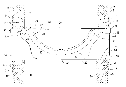
Figure 1 is a side cross-sectional v~.ew of an
embodiment of the intumescent firestopping apparatus of the
present invention;
'~~ Figure 2 is a side cross-sectional view of another
embodiment of the intumescent firestopping apparatus of the
present invention;
Figure 3 is a side cross-sectional view of the
embodiment of the intumescent firestopping apparatus shown
in Figure 2 illustrating the penetrating cables extending
therethrough;
Figure 4 is a side cross-sectional view of a
further alternative embodiment of the present invention
utilizing two pairs of restraining supports and two p
l
' intumescent pads having flexible central sections with
biasing means thereadjacent;
Figure 5 is an end view of an embodiment of a
sleeve of the present invention showing the intumescent pad
extending between the upper and lower tabs; and
16
' CA 02427515 2003-05-O1
i~ '
I
~I
Figure 6 is an illustration similar to Figure 5
showing an alternative embodiment of the foam pads
including a flexed upper central section and a flexed lower
central section each of which defines multiple cuts or
'i' slots therein for enhancing the flexible resilience of the
material and shows the penetrating cables extending
therebetween.
DETAILED DESCRIPTION OF THE PREFERRED EMBODIMENT
The intumescent~firestopping apparatus of the
present invention preferably includes a sleeve 20 which is
adapted to be positioned extending through an opening 17
defined in a construction barrier 16 in standard
residential or commercial construction. These openings 17
are defined in construction barriers 16 such as wall,
~j floors and ceilings in order to allow cables or other
penetrating members 18 to extend therethrough from room to
room or from floor to floor. Normally the sleeve 20 is
positioned within the opening 17 and a mounting plate 18 is
placed surrounding the sleeve and attached to the sleeve
i
'~ such that it can be secured to the area of the construction
barrier 16 immediately adjacent to the opening 17 therein
by way of a securement means 14 such as a screw or the
like. The sleeve can be detachably securable to the
mounting plate 18 or it can be fixedly secured thereto
17
CA 02427515 2003-05-O1
i~
i
allowing use in various different applications. Thus, the
mounting plate 18 could be detachably securable to both the
sleeve 20 and the construction barrier 16 if needed for
usefulness in certain applications. Often it is preferably
that an external gasket 12 will be positioned between the
mounting plate 10 and the construction barrier 16 to
j facilitate sealing therebetween.
When so positioned sleeve 20 defines an access
corridor 22 extending axially therethrough from one room to
~ another or from one floor level to another through which
penetrating members 18 such as cables can extend for
communicating data or other transmission capabilities
between vertically or horizontally adjacent working spaces.
In order to facilitate use of this design with
existing structures having cables or other penetrating
members 18 already in position extending through
construction barriers 16, it is particularly advantageous
to form sleeve 20 with a removable section 21 as shown best
in Figure 4. The removable section 21 can be located in
either side wall 30 or 32 or can be in the lower wall 28 or
the upper wall 26. Figure 4 shows the removable section 21
as the entire upper wall member 26 which can be easily
Ii removed upwardly from the remaining portion of the sleeve
to more easily place pre-existing penetrating members 18
~, extending therethrough. The removable section 21 could
i also comprise only a portion of one of the wall 30, 32, 34
I
18
. ' II CA 02427515 2003-05-O1
i.
i I
or 36. The removable section is solely for the purpose of
providing a means of installing the sleeve 20 of the
present invention around penetrating members already in
i
,,
place extending through an existing wall, ceiling or floor.
i In some applications the size of the openings 17
in the construction barriers 16 is so large that a single
sleeve 20 will not successfully fill the entire opening.
As such, with such larger openings 17 more than one
separate individual sleeve 20 can be stacked vertically,
~l, horizontally or any other direction. This stacking is
greatly enhanced by the inclusion of flat outer sections 24
on the outer portions of the sleeve 20.
Preferably the sleeve 20 will include an upper
wall member 26 as well as a lower wall member 28 both of
'~, which extend completely through the openings 17 and are
spaced apart from one another. Similarly a first side wall
member 30 and a second side wall member 32 will also extend
through the opening 17 and be spaced apart from one
another. Preferably the first side wall member 30 and the
i second side wall member 32 will extend from the upper wall
I member 26 to the lower wall~member 28 to facilitate
defining of the access corridor 22 therebetween.
Preferably the two side wall members 30 and 32 will be 'i
spaced apart and will be approximately parallel to each
3; !
~' other and perpendicularly oriented with respect to the
j
upper wall member 26 and the lower wall member 28 to
!j ,
19
" CA 02427515 2003-05-O1
I
further facilitate stacking and usage thereof. i
The present invention will further include a lower
' intumescent pad 38 adapted. to be positioned at least
partially in abutment with the lower wall member 28 of the
'I
sleeve 20 of the present invention. This lower intumescent
i I
pad will preferably extend across the entire lower portion
of the sleeve 20 in order to define the access corridor 22
thereabove and allow penetrating members such as cable 18
extending therethrough to rest upon the upper surface of
the lower intumescent pad 38.
Also the present invention will include an upper
intumescent pad means 44 positioned above the lower
intumescent pad 38 and at least partially in contact with
the upper wall member 26 of sleeve 20. The upper '!
~ intumescent pad 44 preferably will be of a flexibly
resilient material such as to facilitate flexing thereof
downwardly. Preferably the upper intumescent pad 44 will
include an upper central pad section 46 which will flex
downwardly to a point adjacent to the upper surface of the
lower intumescent pad 38 such as to define therebetween a
confinement area 50 which will be adapted to receive and
dynamically adjustably seal the cables 18 as they extend
through the access corridor 22. To facilitate this
downward flexible resilience the intumescent pad preferably
" will preferably include a foam base material.
The lower intumescent pad means 38 will preferably
CA 02427515 2003-05-O1
y,
i
be held in place by a lower tab means 36 which will be
positioned extending upwardly adjacent to the ends of the
lower intumescent pad 38. The lower tab means 36 will ''
I
extend upwardly preferably from the lower wall member 28.
III In a similar manner the upper wall member 26 will
preferably define upper tab means 34 extending downwardly
i
therefrom adjacent the ends of the upper intumescent pad 44
for the purpose of selectively facilitating retaining of
the upper intumescent pad 44 in this position. Other means
may be utilized for retaining the lower intumescent pad 38
I
and the upper intumescent pad 44 in place such as clips,
adhesives or the like. However the use of the upper and
'. lower tabs 34 and 36 has been found to be particularly '',
i
i advantageous.
i The flexible resilience of the upper intumescent
pad 44 and in particular the upper central pad section 46
can be significantly enhanced by the defining of a
plurality of upper slots 48 extending longitudinally
therealong. These slots 48 will facilitate the flexible
2o resilience of the upper central pad central 46 of upper
intumescent pad 44 in such a manner as to enhance the
dynamic adjustable sealing of the throat area between the
two intumescent pads which is designed for the purpose of
retaining the cables 18 in position therebetween.
~ The resilient flexibility of the upper central pad
i
section 46 extending in a lower direction is enhanced by
21
CA 02427515 2003-05-O1
a
'i
the inclusion of first upper restraining supports 52 and
second upper restraining supports 54. These supports are
best shown in Figure 1 and have the purpose of holding at
least a portion of the upper intumescent pad 44 in position
'j adjacent to the upper wall member 26 while allowing the
upper central pad section 46 thereof to flex downwardly
toward the lower intumescent pad 38 located therebelow. 3n
this manner full intumescent capabilities will be
maintained while providing a dynamically adjustable means
~j for sealing and defining of a throat between the
intumescent pads for receiving cables 18 extending
therethrough. The first upper restraining support 52 and
the second upper restraining support 54 will preferably
define an upper restraining space 55 between these supports
~~ and the upper wall member 26 thereabove to facilitate
retaining of the upper intumescent pad 44 therewithin. The
restraining supports 52 and 54 can comprise tabs cut from
the sleeve and projecting inwardly thereinto to provide
supporting plates to facilitate holding of the pads in
~~ place as best shown in Figures 1 and 4.
To further enhance the downward flexible
resilience of the upper central pad section 46 an upper ,
biasing means such as upper flat spring means 62 may be
included. This flat spring has the purpose of exerting a
!! downwardly directed bias cm the upper central pad section
46 of upper intumescent pad 44 to more firmly engage cables
~2
CA 02427515 2003-05-O1
18 which extend through the confinement area 5o for
retaining them in place while at the same time maintaining
full intumescent capability.
In a further alternative configuration the lower
intumescent pad 38 can include a lower central pad section
40 which is flexibly resilient upwardly in a similar manner
to the upper central pad section 46. This lower central
pad section 40 can include a lower biasing means such as
', lower flat spring 64 for facilitating upward flexing
l0 thereof.
Furthermore the lower central pad section 40 can
~I include a plurality of lower slot means 42 defined therein
I longitudinally to facilitate flexible resilience thereof ',
and upward biasing toward the upper intumescent pad 44.
~ Further as shown best in Figure 4 the lower
intumescent pad 38 can be positioned within a lower
restraining space 6o defined between the first lower
restraining support 56 and the upper wall member 26 as well
as defined between the second lower restraining support 58
and the upper wall member 26. Preferably the first lower
restraining support 56 and the second lower restraining
support 58 will be spaced apart from one another with the
lower central pad section 40 and lower slot means 42, if
included, defined thereon positioned between the
i restraining supports 56 and 58. In this manner the lower
I, central pad section 40 can flex upwardly possibly in
23
. ~ ~i CA 02427515 2003-05-O1
. ~ ,
certain embodiments aided by the lower flat spring means 64
to facilitate engagement thereof with the upper intumescent
pad means 44 thereabove and facilitate the defining of the
confinement area 50 therebetween in a dynamically
'I adjustable manner while maintaining the full intumescent
capability for sealing thereof responsive to fire or heat.
i
It should be appreciated that the present
invention has the sole purpose of providing a sleeve-like
portal for the installation of cables for various purposes
~ such as electrical, data, communication, signal, video
cables or any other penetrating member through fire or
smoke rated walls or other barriers. Such barriers require
self-contained fire and/or smoke sealing mechanisms and the
present invention provides a means for providing this while
also providing the capability of dynamically adjusting to
various cable loads.
The material for the sleeve 20 of the present
invention preferably is chosen from steel or other non-
combustible and/or non-melting material. It is preferably
formed with a square or rectangular cross section to
facilitate stacking as described above. The intumescent
pads preferably include a foam component chosen of one of
various polymers such as polyurethane or silicone or any
other polymer which has the capability of forming a soft
;; resilient foam. The intumescent component of the foam may
I! include expandable graphite, sodium silicate or any other
24
CA 02427515 2003-05-O1
commonly used expansion ingredient which is compatible for
use with the basic foam carrier construction.
While particular embodiments of this invention
have been shown in the drawings and described above, it
i
; will be apparent, that many changes may be made in the
form, arrangement and positioning of the various elements
of the combination. In consideration thereof it should be
; understood that preferred embodiments of this invention
disclosed herein are intended to be illustrative only and
!; not intended to limit the scope of the invention.
~5