Sélection de la langue

Search

Sommaire du brevet 2428615 

Énoncé de désistement de responsabilité concernant l'information provenant de tiers

Une partie des informations de ce site Web a été fournie par des sources externes. Le gouvernement du Canada n'assume aucune responsabilité concernant la précision, l'actualité ou la fiabilité des informations fournies par les sources externes. Les utilisateurs qui désirent employer cette information devraient consulter directement la source des informations. Le contenu fourni par les sources externes n'est pas assujetti aux exigences sur les langues officielles, la protection des renseignements personnels et l'accessibilité.

Disponibilité de l'Abrégé et des Revendications

L'apparition de différences dans le texte et l'image des Revendications et de l'Abrégé dépend du moment auquel le document est publié. Les textes des Revendications et de l'Abrégé sont affichés :

  • lorsque la demande peut être examinée par le public;
  • lorsque le brevet est émis (délivrance).
(12) Demande de brevet: (11) CA 2428615
(54) Titre français: ROBINET A DOUCHETTE POUR CUISINE
(54) Titre anglais: SPRAY HEAD KITCHEN FAUCET
Statut: Réputée abandonnée et au-delà du délai pour le rétablissement - en attente de la réponse à l’avis de communication rejetée
Données bibliographiques
(51) Classification internationale des brevets (CIB):
  • B05B 01/02 (2006.01)
  • B05B 01/16 (2006.01)
  • E03C 01/04 (2006.01)
(72) Inventeurs :
  • OUYOUNG, SCOTT (Taïwan, Province de Chine)
(73) Titulaires :
  • GLOBE UNION INDUSTRIAL CORP.
(71) Demandeurs :
  • GLOBE UNION INDUSTRIAL CORP. (Taïwan, Province de Chine)
(74) Agent: MARKS & CLERK
(74) Co-agent:
(45) Délivré:
(22) Date de dépôt: 2003-05-13
(41) Mise à la disponibilité du public: 2004-11-13
Requête d'examen: 2004-05-06
Licence disponible: S.O.
Cédé au domaine public: S.O.
(25) Langue des documents déposés: Anglais

Traité de coopération en matière de brevets (PCT): Non

(30) Données de priorité de la demande: S.O.

Abrégés

Abrégé anglais


A spray head kitchen faucet essentially comprised of a body including
base holder, adapter, and inner tube, inner cylinder, cartridge, guide,
diverter,
retaining ring, wave generator unit, spout, and control handle, wherein,
displacement of the guide being regulated through the cartridge by the extent
the handle is pressed, and the tap water entering into the body to be
delivered
through the diverter and the sprout in jet or in sprinkle mode.

Revendications

Note : Les revendications sont présentées dans la langue officielle dans laquelle elles ont été soumises.


9
I CLAIM:
1. A sink faucet with spray head comprising:
a body including a base holder, an adapter, an inner tube; the inner tube
being provided in the hollow of the base holder in a reduced supply pipe with
wider bottom and smaller top, the supply pipe having an externally threaded
coupling on its top to be locked into the adapter and on its bottom in larger
diameter being provided with an internally threaded coupling; the adapter
having a hollow provided inside, a threaded coupling hole at the bottom, a
larger opening internally threaded at the front, and a through hole at the
rear;
an inner cylinder, containing a three-gradation hollow, an opening at front,
an
axial hole at the rear, a through hole at bottom where close to the rear, a
cylinder cover provided with an axial being adapted to the rear of the inner
cylinder and placed into the hollow of the adapter, and the top of the inner
tube
being inserted into the through hole at bottom of the inner cylinder;
a guide, containing a hollow with an open front, a protruded rear, an
axial hole and multiple guide holes;
a diverter, having a hollow inside, an opening at front being internally
threaded, a rear protrusion with a through hole in smaller diameter, an
external
gasket with multiple guide holes being provided to where close the protrusion,
the protrusion being incorporated into the hollow of the guide and inserted
into

10
the gradation inside the inner cylinder, the guide being located in the
hollow,
and the second half of the diverter being located in the hollow in the
opening;
a cartridge, a double flange sandwiching a resilient washer being provided at
where closer to the front cartridge, inserted through an axial hole in the
guide
and a through hole in the diverter; the rear of the cartridge being threaded
and
inserted with a coil before passing through the inner cylinder, the adapter,
exposed and locked to a connection sleeve, and a pair of C rings being used to
retain the center of the cartridge in the axial hole of the guide;
a retaining ring, having a hollow, a front opening, a through hole in
diameter smaller than the outer diameter of the washer of the cartridge at the
rear; and a threaded outer circumference to be locked into the hollow of the
diverter;
a wave generator, including a first dispersion member, gasket, strainer
and a secondary dispersion member;
a spout, having a hollow provided with an opening end, threaded outer
circumference being locked to the adapter, a main hole in smaller diameter
being provided at the front to accommodate the wave generator, multiple
minute holes penetrating the front and the hollow being provided on the outer
circumference of the main hole; and
a control handle, having a pivot provided in the upper front, and

11
connected to a connection sleeve by means of a pin.

Description

Note : Les descriptions sont présentées dans la langue officielle dans laquelle elles ont été soumises.

CA 02428615 2003-05-13
TITLE: SPRAY HEAD KITCHEN FAUCET
BACKGROUND OF THE IN~EENTION
(a) Field of the Invention
The present invention is related to a spray head kitchen faucet, and more
particularly, to one provided with an extension for the spray head to be
separately pulled out for use to facilitate washing to clean the kitchen sink
set
or the kitchen.
(b) Description of the Prior Art:
Single handle kitchen faucet generally available in the market is usually
used in modem kitchen, particularly in well-developed countries including
Japan, USA and those in Europe. However, its spout delivers only one mode
of water as that from an ordinary stem faucet and fails to deliver the water
jet
effectively to clean the kitchen or areas other than the sink, thus to
significantly offset the e~cacy of the kitchen faucet.

CA 02428615 2003-05-13
2
SUTr~ARY OF 'THE INVENTION
The primary purpose of the present invention is to provide a kitchen
faucet with a spray head for the kitchen faucet to be more practical in tree
kitchen. To achieve the purpose, a guide and a diverter adapted with a
cartridge are provided to control the tap water enteri7zg into the faucet to
be
delivered out of the spout either in jet or in sprinkle mode depending on the
pressure applied to the handle.
The foregoing object and summary provide only a brief introduction to
the present invention. To fully appreciate these and other objects of the
present invention as well as the invention itself, all of which will become
apparent to those skilled in the art, the following detailed description of
the
invention and the claims should be read in conjunction with the accompanying
drawings. Throughout the specification and drawings identical reference
numerals refer to identical or similar parts.
Many other advantages and features of the present invention will become
manifest to those versed in the art upon making reference to the detailed
description and the accompanying sheets of drawings in which a preferred
structural embodiment incorporating the principles of the present invention is
shown by way of illustrative example.

CA 02428615 2003-05-13
BRIEF DESCRIPTION OF THE DRAWIhTGS
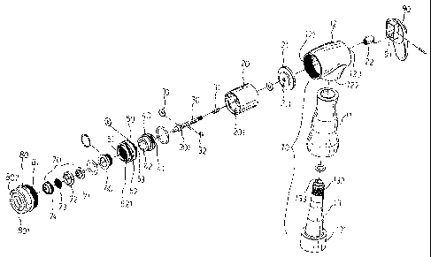
Fig. 1 is an exploded view of a preferred embodiment of the present
invention.
Fig. 2 is a schematic view of the preferred embodiment of the present
invention as assembled.
Fig. 3 is a sectional view showing the preferred embodiment of the
present invention is in use.
Fig. 4 is another sectional view showing the preferred embodiment of
the present invention is in use.
Fig. 5 is another sectional view yet showing the preferred embodiment
of the present invention is in use.

CA 02428615 2003-05-13
DETAILED DESCRIPTION OF TIITE PREFERRED EMBODFVIENT
The following descriptions are of exemplary embodiments only, and are
not intended to limit the scope, applicability or configuration of the
invention
in any way Rather, the following description provides a convenient
illustration for implementing exemplary embodiments of the invention.
Various changes to the described embodiments may be made in the function
and arrangement of the elements described without departing from the scope
of the invention as set forth in the appended claims.
Referring to Figs. l, 2, and 3, a preferred embodiment of the present
invention for a kitchen faucet provided with a spray head is essentially
comprised of a body 10 including a base holder 11, an adapter I2, an inner
tube 13, an inner cylinder 20, a cartridge 30, a guide 40, a diverter 50, a
retaining ring 60, a wave generator 70, a spout 80 and a control handle 90.
The inner tube 13 containing a supply pipe 133 is inserted into the base
holder
11. The supply pipe 133 relates to a reduced pipe having wider bottom and
smaller top. The top of the supply pipe 133 is provided with an externally
threaded coupling 132 to be locked into the adapter 12, and the bottom in
larger diameter is provided with an internally threaded coupling i 21 to be
pivoted to an extension hose (not illustrated). The adapter 12 has a hollow
121 provided inside, a threaded coupling hole 122 at the bottom, a larger

CA 02428615 2003-05-13
opening internally threaded at the front, and a through hole 123 at the rear
to
be connected to the control handle 90. The inner cylinder 20 contains a
three-gradation hollow 20I, an axial hole 203 at the rear for the cartridge 30
to
pass through, and a through hole 202 at bottom and closer to the rear for
receiving the insertion by the inner tube. A cylinder cover 2I having an axial
211 is first connected to the rear of the inner cylinder 20 and the inner
cylinder
is then placed into the hollow I2I of the adapter I2. A double flange 301
sandwiching a resilient washer 33 is provided at where closer to the front
cartridge 30 to be inserted through an axial hole 411 in the guide 40 and a
I 0 through hole 531 in the diverter 50; and the rear of the cartridge 30 is
threaded
and inserted with a coil 3 I before passing through the inner cylinder 20, the
adapter 12 and locked to a connection sleeve 22, which in turn is connected to
a pivot 91 of the control handle 90 by means of a pin. A pair of C rings 32 is
used to retain the center of the cartridge 30 in the axial hole 4I 1 of the
guide
40. The guide 40 is provided with an opening 42 at its front to be coupled to
a protrusion 53 from the end of the diverter 50, and a protrusion 41
containing
an axial hole 41 l and a guide hole 4I2 at its rear. The guide 40 is coupled
to
the diverter 50 and rests on the second gradation in the inner cylinder 20
while
the second half of the diverter rests in the opening of the guide 40. The
diverter 50 has a hollow 51, a threaded opening in front to be locked to the

CA 02428615 2003-05-13
6
retainer ring 60, a protrusion 53 in the rear to be inserted into the hollow
42 of
the guide 40, and an outer gasket 52 at the protrusion 53 provided on its end
surface multiple guide holes 521 penetrating through the outer gasket 52.
The retainer ring 60 has an opening at front, a through hole 601 in a diameter
slightly smaller than that of the washer 33, and the outer circumference being
threaded to be locked to the hollow 51 in the diverter 50. An externally
threaded coupling 81 is provided to the rear of the spout 80 for the spout 80
to
be locked into the opening of the adapter 12, and a hollow 811 with an
opening in the spout 80 is provided to accommodate the diverter 50, and a
main hole 801 in smaller diameter is provided at the front of the spout 80 to
accommodate a wave generator 70 comprised of a first dispersion member 71,
a washer 72 and a strainer 73, and a second dispersion member 74. Wherein,
the first dispersion member is provided with a central hole and a side groove,
and the second dispersion member is also provided with a side groove.
Multiple minute pores 802 penetrating through the hollow 811 are provided on
the outer circumference of the main. hole 801.
As illustrated in Figs. 4 and 5, a proper force is applied onto the cantrol
handle 90 to press it down for a certain extent before ing it to pull back the
connection sleeve 22 pivoted to the control handle 90 and in tum, to pull back
the cartridge 30. Both of the guide 40 and the washer 33 move backward to

CA 02428615 2003-05-13
7
permit the through hole 601 of the retainer ring 60 to open. Meanwhile,
water entering from the inner tube of the body 10 flows through the guide hole
412 of the guide 40, then diverted by the through hole 531 of the diverter,
then
the through hole 601 of the retainer ring 60 and the wave generator 70 to be
S forced to increase the flow velocity and form a powerful jet upon leaving
the
main hole 801 of the spout 80. As illustrated in Fig. 5, when an even greater
force is applied to press and rotate aI1 way down the control handle 90, the
cartridge 30 is given its ma~~imal displacement at the same time to move the
guide 40 back until it is cleared away from the protrusion 53 of the diverter
50.
In turn, the hollow 42 of the guide 40 is connected through the guide hole 521
of the diverter 50, and the retreating washer 33 closes up the through hole
513
of the diverter 50. Therefore, the water entering from the inner tube 13 flows
through the guide hole 412 of the guide to the spout 80 through the guide hole
521 of the guide 50 to sprinkle the water from those multiple minute pores 802
of the spout 80. When the control handle 90 is released, the cartridge 41 for
being subject to the coil 31 returns to its place in the configuration as
illustrated in Fig. 3, and stops the delivery of water since both of the
through
hole 601 of the retaining ring 60 and the guide hole 521 of the diverter SO
are
closed up.
It will be understood that each of the elements described abo~re, or two or

CA 02428615 2003-05-13
more together may also find a useful application in other types of methods
differing from the type described above.
While certain novel features of this invention have been shown and
described and are pointed out in the annexed claim, it is not intended to ~be
limited to the details above, since it will be understood that various
omissions,
modifications, substitutions and changes in the forms and details of the
device
illustrated and in its operation can be made by those skilled in the art
without
departing in any way from the spirit of the present invention.

Dessin représentatif
Une figure unique qui représente un dessin illustrant l'invention.
États administratifs

2024-08-01 : Dans le cadre de la transition vers les Brevets de nouvelle génération (BNG), la base de données sur les brevets canadiens (BDBC) contient désormais un Historique d'événement plus détaillé, qui reproduit le Journal des événements de notre nouvelle solution interne.

Veuillez noter que les événements débutant par « Inactive : » se réfèrent à des événements qui ne sont plus utilisés dans notre nouvelle solution interne.

Pour une meilleure compréhension de l'état de la demande ou brevet qui figure sur cette page, la rubrique Mise en garde , et les descriptions de Brevet , Historique d'événement , Taxes périodiques et Historique des paiements devraient être consultées.

Historique d'événement

Description Date
Demande non rétablie avant l'échéance 2007-05-14
Le délai pour l'annulation est expiré 2007-05-14
Réputée abandonnée - omission de répondre à un avis sur les taxes pour le maintien en état 2006-05-15
Inactive : CIB de MCD 2006-03-12
Demande publiée (accessible au public) 2004-11-13
Inactive : Page couverture publiée 2004-11-12
Inactive : Lettre officielle 2004-07-08
Exigences relatives à la révocation de la nomination d'un agent - jugée conforme 2004-07-08
Exigences relatives à la nomination d'un agent - jugée conforme 2004-07-08
Demande visant la nomination d'un agent 2004-06-03
Demande visant la révocation de la nomination d'un agent 2004-06-03
Inactive : Lettre officielle 2004-05-18
Inactive : Demande ad hoc documentée 2004-05-18
Inactive : Lettre officielle 2004-05-18
Lettre envoyée 2004-05-13
Demande visant la nomination d'un agent 2004-05-06
Exigences pour une requête d'examen - jugée conforme 2004-05-06
Toutes les exigences pour l'examen - jugée conforme 2004-05-06
Requête d'examen reçue 2004-05-06
Demande visant la révocation de la nomination d'un agent 2004-05-06
Inactive : CIB attribuée 2003-07-14
Inactive : CIB en 1re position 2003-07-14
Inactive : Certificat de dépôt - Sans RE (Anglais) 2003-06-11
Lettre envoyée 2003-06-11
Demande reçue - nationale ordinaire 2003-06-11

Historique d'abandonnement

Date d'abandonnement Raison Date de rétablissement
2006-05-15

Taxes périodiques

Le dernier paiement a été reçu le 2005-02-23

Avis : Si le paiement en totalité n'a pas été reçu au plus tard à la date indiquée, une taxe supplémentaire peut être imposée, soit une des taxes suivantes :

  • taxe de rétablissement ;
  • taxe pour paiement en souffrance ; ou
  • taxe additionnelle pour le renversement d'une péremption réputée.

Les taxes sur les brevets sont ajustées au 1er janvier de chaque année. Les montants ci-dessus sont les montants actuels s'ils sont reçus au plus tard le 31 décembre de l'année en cours.
Veuillez vous référer à la page web des taxes sur les brevets de l'OPIC pour voir tous les montants actuels des taxes.

Historique des taxes

Type de taxes Anniversaire Échéance Date payée
Taxe pour le dépôt - petite 2003-05-13
Enregistrement d'un document 2003-05-13
Requête d'examen - petite 2004-05-06
TM (demande, 2e anniv.) - petite 02 2005-05-13 2005-02-23
Titulaires au dossier

Les titulaires actuels et antérieures au dossier sont affichés en ordre alphabétique.

Titulaires actuels au dossier
GLOBE UNION INDUSTRIAL CORP.
Titulaires antérieures au dossier
SCOTT OUYOUNG
Les propriétaires antérieurs qui ne figurent pas dans la liste des « Propriétaires au dossier » apparaîtront dans d'autres documents au dossier.
Documents

Pour visionner les fichiers sélectionnés, entrer le code reCAPTCHA :


Pour visualiser une image, cliquer sur un lien dans la colonne description du document. Pour télécharger l'image (les images), cliquer l'une ou plusieurs cases à cocher dans la première colonne et ensuite cliquer sur le bouton "Télécharger sélection en format PDF (archive Zip)" ou le bouton "Télécharger sélection (en un fichier PDF fusionné)".

Liste des documents de brevet publiés et non publiés sur la BDBC .

Si vous avez des difficultés à accéder au contenu, veuillez communiquer avec le Centre de services à la clientèle au 1-866-997-1936, ou envoyer un courriel au Centre de service à la clientèle de l'OPIC.


Description du
Document 
Date
(aaaa-mm-jj) 
Nombre de pages   Taille de l'image (Ko) 
Dessins 2003-05-12 5 132
Revendications 2003-05-12 3 94
Description 2003-05-12 8 303
Abrégé 2003-05-12 1 18
Dessin représentatif 2004-10-21 1 14
Courtoisie - Certificat d'enregistrement (document(s) connexe(s)) 2003-06-10 1 105
Certificat de dépôt (anglais) 2003-06-10 1 158
Accusé de réception de la requête d'examen 2004-05-12 1 176
Rappel de taxe de maintien due 2005-01-16 1 109
Courtoisie - Lettre d'abandon (taxe de maintien en état) 2006-07-09 1 175
Correspondance 2004-05-05 1 26
Correspondance 2004-05-12 2 105
Correspondance 2004-05-17 1 18
Correspondance 2004-05-17 1 12
Correspondance 2004-06-02 1 28
Correspondance 2004-07-07 1 20
Taxes 2005-02-22 1 54