Sélection de la langue

Search

Sommaire du brevet 2428681 

Énoncé de désistement de responsabilité concernant l'information provenant de tiers

Une partie des informations de ce site Web a été fournie par des sources externes. Le gouvernement du Canada n'assume aucune responsabilité concernant la précision, l'actualité ou la fiabilité des informations fournies par les sources externes. Les utilisateurs qui désirent employer cette information devraient consulter directement la source des informations. Le contenu fourni par les sources externes n'est pas assujetti aux exigences sur les langues officielles, la protection des renseignements personnels et l'accessibilité.

Disponibilité de l'Abrégé et des Revendications

L'apparition de différences dans le texte et l'image des Revendications et de l'Abrégé dépend du moment auquel le document est publié. Les textes des Revendications et de l'Abrégé sont affichés :

  • lorsque la demande peut être examinée par le public;
  • lorsque le brevet est émis (délivrance).
(12) Demande de brevet: (11) CA 2428681
(54) Titre français: SYSTEME DE FERMETURE EN MATIERE PLASTIQUE RESILIENT, NOTAMMENT POUR BOUTEILLES
(54) Titre anglais: CLOSURE MADE OF A FLEXIBLE PLASTIC FOR CONTAINERS, ESPECIALLY FOR BOTTLES
Statut: Réputée abandonnée et au-delà du délai pour le rétablissement - en attente de la réponse à l’avis de communication rejetée
Données bibliographiques
(51) Classification internationale des brevets (CIB):
  • B65D 47/14 (2006.01)
  • B65D 47/08 (2006.01)
(72) Inventeurs :
  • KLOPFER, MANFRED (Autriche)
(73) Titulaires :
  • ALPLA-WERKE ALWIN LEHNER GMBH & CO. KG
(71) Demandeurs :
  • ALPLA-WERKE ALWIN LEHNER GMBH & CO. KG (Autriche)
(74) Agent: MOFFAT & CO.
(74) Co-agent:
(45) Délivré:
(86) Date de dépôt PCT: 2001-11-09
(87) Mise à la disponibilité du public: 2002-05-30
Requête d'examen: 2003-05-13
Licence disponible: S.O.
Cédé au domaine public: S.O.
(25) Langue des documents déposés: Anglais

Traité de coopération en matière de brevets (PCT): Oui
(86) Numéro de la demande PCT: PCT/EP2001/012955
(87) Numéro de publication internationale PCT: EP2001012955
(85) Entrée nationale: 2003-05-13

(30) Données de priorité de la demande:
Numéro de la demande Pays / territoire Date
2000 2303/00 (Suisse) 2000-11-27

Abrégés

Abrégé français

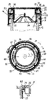
L'invention concerne un système de fermeture comprenant une partie annulaire (11) sur laquelle est articulé un couvercle (17) au moyen d'une charnière (19) et une partie de déversement (25) introduite dans la partie annulaire (1). Au moment où la partie de déversement (25) est introduite, l'arête de ladite partie de déversement (29) vient buter contre les segments (27) et adopte ainsi la forme optimale pour empêcher les phénomènes de dégouttage. Au moment où le couvercle (17) est fermé, l'air situé dans la rainure peut se dégager par les sorties (45), de sorte à ne pas entraver la fermeture ou de sorte à ne pas avoir tendance à ouvrir le système de fermeture. Au moment de la fermeture, l'extrémité supérieure (28) de la partie de déversement (25) vient au contact des surfaces d'appui (50) situées à distance mutuelle dans la rainure (23), le liquide résiduel trouvant à se loger dans les cavités (49).


Abrégé anglais


The inventive closure is comprised of the annular part (11), to which a lid
(17) is joined by means of a hinge (19), and of the spout (25) that is pushed
inside the annular part (11). When pushing the spout (25) into the annular
part, the edge of the spout (29) abuts against segments (47) and is thus
brought into the optimal drop-preventing shape. When closing the lid (17), the
air in the slot can escape through the outlets (45) so that it does not impede
the closing or have the tendency to open the closure. Also during closing, the
upper end (28) of the spout (25) comes into contact with the supporting
surfaces (50), which are arranged in an interspaced manner inside the slot
(23), whereby remaining liquid can be accommodated in the cavities (49).

Revendications

Note : Les revendications sont présentées dans la langue officielle dans laquelle elles ont été soumises.


Claims
1. A closure of flexible plastic for containers, in particular bottles, having
a ring
(11) which has means (13) for securing it to the container neck (15), having a
lid (17)
which is joined to the ring (11) by means of a hinge (19) and has a stopper
(21) that is
surrounded on the upper end by an annular slot (23), having a tubular spout
(25), which
can be introduced sealingly by its lower end (27) into the container neck (15)
and on the
upper end (28) has a drip-preventing edge (29) of the spout, which when the
closure is
closed engages the annular slot (23) of the lid (17), characterized in that
the annular slot
(23) has at least one outlet (45).
2. The closure of claim 1, characterized in that the annular slot is formed by
the
space (23) between the stopper (21) and an annular flange (35) disposed
coaxially to the
stopper.
3. The closure of claim 2, characterized in that the respective outlet (45) is
formed
by a slit in the annular flange (35).
4. The closure of one of claims 1-3, characterized in that the diameter (d v)
of the
spout (25) measured via the edges (29) of the spout is somewhat greater than
the outer
diameter (d n) of the annular slot (23).
5. The closure of one of claims 1-4, characterized in that supporting surfaces
(50)
for the end (28) of the spout are provided, spaced apart from one another, on
the bottom
of the annular slot (23).
6. The closure of one of claims 1-5, characterized in that a collar (31) on
the spout
is provided, which when the closure is placed on the container neck (15) comes
to rest
on the end (33) of the container neck (15).
7. The closure of claim 6, characterized in that the lid (17) always has cuffs
(52)
-7-

which rest on the collar (31) when the closure is closed.
8. The closure of one of claims 1-7, characterized in that it is in one piece.
9. The closure of one of claims 1-8, characterized in that the spout (25) is
inserted
as a separate part into the ring (11).
10. The closure of one of claims 1-9, characterized in that it has a proof-of-
originality strip (55) that can be broken off.
11. A closure of flexible plastic for containers, in particular bottles,
having a ring
(11) which has means (13) for securing it to the container neck (15), having a
lid (17)
which is joined to the ring (11) by means of a hinge (19) and has a stopper
(21) that is
surrounded on the upper end by an annular slot (23), having a tubular spout
(25), which
can be introduced sealingly by its lower end (27) into the container neck (15)
and on the
upper end (28) has a drip-preventing edge (29) of the spout, which when the
closure is
closed engages the annular slot (23) of the lid (17), characterized in that
the diameter (d v)
of the spout (25) measured via the edges (29) of the spout is somewhat greater
than the
outer diameter (d n) of the annular slot (23).
-8-

Description

Note : Les descriptions sont présentées dans la langue officielle dans laquelle elles ont été soumises.


CA 02428681 2003-05-13
WO 02/42174 PCT/EP 01/12955
CLOSURE MADE OF A FLEXIBLE PLASTIC FOR
CONTAINERS, ESPECIALLY FOR BOTTLES
[0001] The invention relates to a closure of flexible plastic for containers,
in
particular bottles, having a ring which has means for securing it to the
container neck,
having a lid which is joined to the ring by means of a hinge and has a stopper
that is
surrounded on the upper end by an annular slot, having a tubular spout, which
can be
introduced sealingly by its lower end into the container neck and on the upper
end has a
drip-preventing edge of the spout, which when the closure is closed engages
the annular
slot of the lid.
[0002] One such closure is disclosed in a one-piece embodiment in Spanish
patent
disclosure ES-A-9103392, for instance. Two-piece versions are described in
European
patent disclosure EP 0 685 406, Spanish Utility Model 87024456, Brazilian
Utility
Model 7400915, and in French patent disclosure FR-A-2749565 and BR-A-9605553
that
corresponds to it.
[0003] This known prior art will now be described in further detail in
conjunction
with Figs. 1-4. In Figs. 1 and 2, a known closure is shown, of the kind found
in EP-A-
0 685 406, Spanish Utility Model 9103392 and Brazilian Utility Model 7400915.
This
closure has a ring 11, which has means 13 for securing it to the container
neck 15. The
lid 17 is joined to the ring 11 by means of a hinge 19 and has a stopper 21,
which is
surrounded on the upper end by an annular slot 23. The tubular spout 25 is
embodied as
a separate part. The spout 25 can be introduced sealingly by its lower end 27
into the
container neck 15. On the upper end 28, it has a drip-preventing edge 29 of
the spout,
which when the closure is closed (Fig. 2) engages the annular slot 23.
[0004] The edge 29 of the spout has the usual shape, which can be described by
saying that the edge is curved outward and downward.
[0005] The spout 25 has a collar 31, which in cross section, together with the
outlet
wall, has the shape of an inverted U.

CA 02428681 2003-05-13
WO 02/42174 PCT/EP 01/12955
[0006] When the closure is seated on the neck 15 of the bottle, various
sealing
points exist, namely between the lower part 27 of the spout 25 and the inner
wall of the
container neck 15; between the collar 31 and the upper end of the neck 15 of
the bottle;
between the stopper 21 and the inner wall of the spout 25; and between the
bottom 24 of
the slot 23 and the upper portion 28 of the spout 25.
[0007] In FR-A-2 749 565 (BOER-A-9605553), an improvement in the seal
between the spout and the lid is proposed, as will now be described in further
detail in
conjunction with Fig. 3. An annular flange 35 is disposed coaxially to the
stopper 21, so
that between them an annular slot 23 is formed. When the closure is closed,
this slot 23
fittingly receives the upper end 23 of the spout 25, whereupon the end 28 of
the spout
comes to rest, or is intended to come to rest, on the bottom 24 of the slot
23. A
disadvantage of this is that when the closure is closed after use of the
container, air
remains caught in the annular slot 23, becomes compressed, and has the
tendency to re-
open the closure. The same is correspondingly true for liquid residues, such
as oil,
adhering to the spout 25 after liquid has been poured out. To counteract the
tendency to
unwanted opening, this reference proposes the provision of a snap device of
the kind
disclosed for instance by FR-A-2706425. This known device is shown in Fig. 4.
The
locking of the lid 17 is provided by the bead 41, which extends annularly
around the
stopper 21 and which upon closure of the lid 17 is thrust over the annular
bead 43 in the
interior of the spout 25. A disadvantage of this is that a relatively great
expenditure of
force is required for closure. Another disadvantage is that such beads make
mold
construction more expensive and unmolding of the closures more difficult,
because the
beads have to be pulled out of the indentations in the mold.
[0008] It is therefore the object of the present invention to improve a
closure of the
generic type defined at the outset. In particular, a closure is to be created
that is simple
in design and nevertheless assures secure closure. According to the invention,
in a
closure of the type defined at the outset, this is attained in that the
annular slot has at
least one outlet. Upon closure of the closure, the air in the annular slot can
flow out
through this outlet, so that an overpressure having the tendency to lift the
lid off again
_2_

CA 02428681 2003-05-13
WO 02/42174 PCT/EP 01/12955
cannot be created in the slot.
[0009] Expediently, the annular slot is formed by the space between the
stopper and
an annular flange disposed coaxially to the stopper. This makes it possible
for the
respective outlet to be formed by a slit in the annular flange.
[0010] Advantageously, the diameter of the spout measured via the edge of the
spout is somewhat greater than the outer diameter d~ of the annular slot. Upon
insertion
of the spout into the annular closure part, the edge of the spout therefore
enters into
contact with the annular flange and is bent downward. As a result, it is given
an optimal
shape, which in use of the container acts to prevent dripping.
[0011] Expediently, supporting surfaces for the spout are provided, spaced
apart
from one another, on the bottom of the annular slot. Because these supporting
surfaces
are in contact with the spout, when the closure is placed on the container,
the forces
acting on the lid are transmitted to the spout. Since the spout rests only on
these
supporting surfaces, there is an interstice between the upper end of the
closure and the
bottom of the slot, in which small residues of liquid that might be adhering
to the spout
fmd space, so that they do not escape from the outlet.
[0012] A collar on the spout can be provided, which when the closure is placed
on
the container neck comes to rest on the end of the container neck. The lid
advantageously has inner cuffs which rest on the collar when the closure is
closed.
These cuffs likewise serve to transmit the force from the lid to the spout
when the
closure is placed on the container.
[0013] The closure can be made in one piece or two pieces. In the two-piece
version, the tubular spout is inserted as a separate part into the ring.
[0014] As in the prior art described in the introduction, it can have a proof
of-
originality strip that can be broken off.
-3-

CA 02428681 2003-05-13
WO 02/42174 PCT/EP 01/12955
[0015] One exemplary embodiment of the invention will now be described in
conjunction with the drawing. For better comprehension of the invention,
however, the
known prior art has been described above in conjunction with Figs. 1-4. Shown
schematically and not to scale are:
(0016] Fig. 1, a known two-piece closure in the open state;
[0017] Fig. 2, the closure of Fig. 1 in the closed state;
[0018] Fig. 3, a known refinement of the closure of Figs. 1 and 2;
[0019] Fig. 4, a further known closure with a snap device;
[0020] Fig. 5, a section through an exemplary embodiment of the closure of the
invention after it has been placed on a container neck;
[0021] Fig. 6, a view of the closure of Fig. 5 from below, but without the
spout
inserted;
[0022] Fig. 7, a section not to scale taken along the line A-A in Fig. 6;
[0023] Fig. 8, a section not to scale taken along the line B-B in Fig. 6;
[0024] Fig. 9, a section not to scale taken along the line C-C in Fig. 6; and
[0025] Fig. 10, the insertion of the spout into the other closure part.
[0026] The closure in the exemplary embodiment of Figs. 5-9 has a design
similar
to the known closure that has been described above in conjunction with Figs. 1-
3. The
exemplary embodiment has a two-piece embodiment. However, it would also be
possible to make the closure in one piece. The closure has a ring 11, which
has means
13 for fastening to the container neck 15. The lid 17 is joined to the ring 11
by means
-4-

CA 02428681 2003-05-13
WO 02/42174 PCT/EP 01/12955
of a hinge 19 and has a stopper 21. The tubular spout 25 is inserted as a
separate part
into the ring 11 and after the insertion forms a unit with the ring. Such
units are used
for closing the containers. The fastening means 13 engage the container neck
15, and
the spout 25 rests sealingly with its lower end 27 on the inner wall of the
container neck
15.
[0027] The spout 25 on its upper end 28, has a drip- preventing edge 29 of the
spout, which has the usual shape, that is, is curved outward and downward. In
the
production of the spout 25, the diameter d~ measured via the edges 29 of the
spout can
be made somewhat larger than the outer diameter do of the slot 23. When the
closure is
put together, the edge 29 of the spout therefore strikes the flange 35 and
thus put into the
optimal drip-preventing shape (Fig. 10). The spout 25 has a collar 31, which
together
with the spout wall has the form of an inverted U. After the closure is put in
place, the
collar 31 rests on the upper end 33 of the container neck. A grid 34 that
serves to
regulate the flow is embodied in the interior of the spout 25 in a known
manner.
[0028] An annular flange 35 is disposed on the lid 17, coaxially with the
stopper,
so that an annular slot 23 is formed between the stopper 21 and the flange 35.
[0029] In contrast to the prior art described at the outset, however, there is
at least
one outlet or slit 45. As Fig. 6 shows, this outlet can for instance be
embodied as an
opening in the annular flange 35. In the exemplary embodiment shown, six such
outlets
45 or openings are provided, so that the annular flange 35 is divided into six
segments
47.
[0030] As Fig. 6 in combination with Fig. 9 shows, supporting surfaces 50 for
the
upper end 28 of the spout 25 are located on the bottom 24 of the slot 23,
spaced apart
from one another. As Figs. 7 and 8 show, between the upper end 28 of the spout
25 and
the bottom 24 there are thus cavities 49, in which any residual liquid
adhering to the
edge 29 of the spout can be received. In contrast to the prior art described,
no sealing
takes place between the end 28 and the bottom 24. It can be seen, however,
that upon
closure of the lid 17, no air remains caught in the slot 23 but instead can
escape through
-5-

CA 02428681 2003-05-13
WO 02/42174 PCT/EP 01/12955
the outlets 45 between the segments 47.
(0031] Cuffs 52 are embodied on the lid 17, distributed over its
circumference;
when the closure is closed, they rest on the collar 31. When the closure is
placed on the
container neck 15, they have the task of transmitting forces from the lid to
the collar 31.
[0032] The exemplary embodiment shown in Figs. 5 and 6 also shows a proof of
originality strip 55 that can be broken away.
[0033] In summary, the following can be stated:
(0034] The closure comprises both the annular part 11, to which a lid 17 is
pivotably connected by means of the hinge 19, and the spout 25 that is
inserted into the
annular part 11. When the spout 25 is inserted, the edge 29 of the spout
strikes the
segments 47 and is thus put into the optimal drip-preventing shape. Upon
closure of the
lid 17, the air in the slot can escape through the outlets 45, so that the air
does not
hinder the closing or have the tendency to open the closure. Moreover upon
closing, the
upper end 28 of the spout 25 comes into contact with the supporting surfaces
50, which
are spaced apart from one another in the slot 23, and any liquid residues can
be held in
the cavities 49.
-6-

Dessin représentatif
Une figure unique qui représente un dessin illustrant l'invention.
États administratifs

2024-08-01 : Dans le cadre de la transition vers les Brevets de nouvelle génération (BNG), la base de données sur les brevets canadiens (BDBC) contient désormais un Historique d'événement plus détaillé, qui reproduit le Journal des événements de notre nouvelle solution interne.

Veuillez noter que les événements débutant par « Inactive : » se réfèrent à des événements qui ne sont plus utilisés dans notre nouvelle solution interne.

Pour une meilleure compréhension de l'état de la demande ou brevet qui figure sur cette page, la rubrique Mise en garde , et les descriptions de Brevet , Historique d'événement , Taxes périodiques et Historique des paiements devraient être consultées.

Historique d'événement

Description Date
Demande non rétablie avant l'échéance 2006-11-09
Le délai pour l'annulation est expiré 2006-11-09
Inactive : Abandon. - Aucune rép dem par.30(2) Règles 2006-01-16
Réputée abandonnée - omission de répondre à un avis sur les taxes pour le maintien en état 2005-11-09
Inactive : Dem. de l'examinateur par.30(2) Règles 2005-07-14
Inactive : IPRP reçu 2003-10-07
Lettre envoyée 2003-08-28
Inactive : Transfert individuel 2003-07-23
Inactive : Lettre de courtoisie - Preuve 2003-07-22
Inactive : Page couverture publiée 2003-07-16
Lettre envoyée 2003-07-14
Inactive : Acc. récept. de l'entrée phase nat. - RE 2003-07-14
Exigences relatives à une correction du demandeur - jugée conforme 2003-07-14
Demande reçue - PCT 2003-06-12
Exigences pour l'entrée dans la phase nationale - jugée conforme 2003-05-13
Exigences pour une requête d'examen - jugée conforme 2003-05-13
Toutes les exigences pour l'examen - jugée conforme 2003-05-13
Demande publiée (accessible au public) 2002-05-30

Historique d'abandonnement

Date d'abandonnement Raison Date de rétablissement
2005-11-09

Taxes périodiques

Le dernier paiement a été reçu le 2004-10-29

Avis : Si le paiement en totalité n'a pas été reçu au plus tard à la date indiquée, une taxe supplémentaire peut être imposée, soit une des taxes suivantes :

  • taxe de rétablissement ;
  • taxe pour paiement en souffrance ; ou
  • taxe additionnelle pour le renversement d'une péremption réputée.

Les taxes sur les brevets sont ajustées au 1er janvier de chaque année. Les montants ci-dessus sont les montants actuels s'ils sont reçus au plus tard le 31 décembre de l'année en cours.
Veuillez vous référer à la page web des taxes sur les brevets de l'OPIC pour voir tous les montants actuels des taxes.

Historique des taxes

Type de taxes Anniversaire Échéance Date payée
Taxe nationale de base - générale 2003-05-13
Requête d'examen - générale 2003-05-13
TM (demande, 2e anniv.) - générale 02 2003-11-10 2003-07-10
Enregistrement d'un document 2003-07-23
TM (demande, 3e anniv.) - générale 03 2004-11-09 2004-10-29
Titulaires au dossier

Les titulaires actuels et antérieures au dossier sont affichés en ordre alphabétique.

Titulaires actuels au dossier
ALPLA-WERKE ALWIN LEHNER GMBH & CO. KG
Titulaires antérieures au dossier
MANFRED KLOPFER
Les propriétaires antérieurs qui ne figurent pas dans la liste des « Propriétaires au dossier » apparaîtront dans d'autres documents au dossier.
Documents

Pour visionner les fichiers sélectionnés, entrer le code reCAPTCHA :


Pour visualiser une image, cliquer sur un lien dans la colonne description du document. Pour télécharger l'image (les images), cliquer l'une ou plusieurs cases à cocher dans la première colonne et ensuite cliquer sur le bouton "Télécharger sélection en format PDF (archive Zip)" ou le bouton "Télécharger sélection (en un fichier PDF fusionné)".

Liste des documents de brevet publiés et non publiés sur la BDBC .

Si vous avez des difficultés à accéder au contenu, veuillez communiquer avec le Centre de services à la clientèle au 1-866-997-1936, ou envoyer un courriel au Centre de service à la clientèle de l'OPIC.


Description du
Document 
Date
(aaaa-mm-jj) 
Nombre de pages   Taille de l'image (Ko) 
Description 2003-05-12 6 293
Dessins 2003-05-12 4 143
Revendications 2003-05-12 2 73
Abrégé 2003-05-12 2 95
Dessin représentatif 2003-07-15 1 20
Accusé de réception de la requête d'examen 2003-07-13 1 173
Rappel de taxe de maintien due 2003-07-13 1 106
Avis d'entree dans la phase nationale 2003-07-13 1 197
Courtoisie - Certificat d'enregistrement (document(s) connexe(s)) 2003-08-27 1 106
Courtoisie - Lettre d'abandon (taxe de maintien en état) 2006-01-03 1 174
Courtoisie - Lettre d'abandon (R30(2)) 2006-03-26 1 166
PCT 2003-05-12 7 205
Correspondance 2003-07-13 1 24
Taxes 2003-07-09 1 40
PCT 2003-05-13 2 72
Taxes 2004-10-28 1 35