Note : Les descriptions sont présentées dans la langue officielle dans laquelle elles ont été soumises.
CA 02429054 2003-05-22
WO 02/38629 PCT/USO1/51006
-1-
POLYMERIZATION PROCESS
[0001 ] The present invention relates to a method to improve a gas phase
reactor
polynerization process by injecting a cooled recycle gas directly into the
plenum of a gas
phase reactor, preferably during high levels of a condensing mode gas phase
process.
[0001 ] Advances in polymerization and catalysis have resulted in the
capability to
produce many new polymers having improved physical and chemical properties
useful in a
wide variety of superior products and applications. With the development of
new catalysts,
the choice of polymerization conditions (solution, slurry, high pressure or
gas phase) for
producing a particular polymer has been greatly expanded. Also, advances in
polymerization technology have provided more efficient, highly productive and
economically enhanced processes. Especially illustrative of these advances is
the
development of technology utilizing bulky ligand metallocene catalyst systems
in slurry or
gas phase. There is a desire in the industry using this technology to reduce
the complexity
of the process, to improve the process operability, to increase product
characteristics and to
vary catalyst choices. Thus, it would be advantageous to have a process that
is capable of
improving one or more of these industry needs.
[0002] In particular there exists a need in the industry to improve gas phase
reactor
operations and operation costs and/or resin particle formation .in gas phase
systems that can
polymerize olefins using a solution fed catalyst system.
[0003] The temperature of the plenum gas flow in a gas or slurry phase system
affects the performance of the catalyst. If the temperature is tao low, such
as for example
near or below the dew point of the cycle gas, the catalyst system injected
into the region of
the fluidized bed at the plenum takes longer to dry and in the presence of
rapid
polymerization systems may lead to the formation of small resin particle
agglomerates of
deficient size and morphology for optimal fluid bed operation. If the
temperature of the
plenum gas flow is too high, the spray or slurry containing the catalyst
system may dry out
too rapidly resulting in extremely fine resin particles or particles fusing
together due to high
temperatures and poor cooling during the ilutial stages of polymerization.
Catalyst
productivity may also be reduced by excessive initial temperatures of the
plenum gas flow.
It is desirable to control temperature of the plenum gas flow (particle
deflecting gas) within
CA 02429054 2005-06-30
-2-
a range that, depending upon the particular catalyst and process conditions,
results in high
catalyst activity and a resin morphology conducive to good mixing and
operation of the
fluid bed reactor.
[0004] U.S. Patent No. 5,693,727 discloses plenum usage in gas phase
polymerization where the recycle stream or a portion thereof is cooled and the
recycle
stream is returned directly to the reactor.
[0005] The instant invention provides a method to control plenum gas flow
temperature by cooling a portion of the recycle gas and returning it to one
reactor via the
plenum.
[0006] This invention relates to a method to polymerize olefins) comprising
contacting one or more monomers) with a catalyst system in a gas phase reactor
having a
recycle system, for removing a recycle gas and unreacted monomers) from the
reactor and
returning the recycle gas and fresh monomers) to the reactor, and a plenum,
the method
comprising the steps of: (a) cooling the recycle gas to form a cooled recycle
gas; (b)
optionally combining the cooled recycle gas with additional recycle gas; and
(c) injecting
the cooled recycle gas into the gas phase reactor through the plenum.
[0007] According to an aspect of the present invention, there is provided a
method
to polymerize olefins) comprising contacting one or more monomers) with a
catalyst
system in a gas phase reactor having a plenum and a recycle system for
removing a recycle
gas and unreacted monomers) from the reactor and returning a portion of the
recycle gas
and fresh monomers) to the reactor, the method, further comprising:
(a) cooling a portion of the recycle gas to form a cooled recycle plenum gas;
(b) optionally combining the cooled recycle plenum gas with additional recycle
gas that has been heated or cooled to control a recycle plenum gas
temperature;
and
(c) injecting the recycle plenum gas into the gas phase reactor through the
plenum.
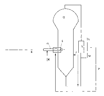
[0008] Figure 1 illustrates a possible equipment configuration to utilize the
invention.
[0009] Please refer to Figure 1 for the letters in parenthesis. A plenum is a
device
used to create a particle lean zone in a fluidized bed gas-phase reactor, as
described in detail
in U.S. Patent No. 5,693,727. A plenum, as referred to herein, conveys recycle
gas or fee
CA 02429054 2005-06-30
-2a-
monomer(s), inerts, and chain transfer agents (such as hydrogen) into the
polymerization
zone. In a preferred embodiment, cycle gas is removed after being compressed
and is then
directed to the side of the fluidized zone. The plenum can range from 4 to 24
inches (10 to
61 cm), preferably 6 to 12 inches (15 to 31 cm). In a preferred embodiment,
the plenum
S comprises an injection tube and a support tube surrounding the injection
tube. Generally
speaking, a catalyst mixture is typically passed through an injection tube
(R)(such as a 1/8
inch (0.3 cm) tube) into a gas phase reactor (Q). The injection tube (R) may
be supported
inside a larger support tube (O), such as a 1 inch (2.54 cm) tube. In a
preferred
embodiment, part of the recycle gas (M), preferably up to 50 weight % (based
upon the
total weight of the recycle gas), more preferably up to 40 weight %, more
preferably up to
30 weight % is cooled, preferably in a heat exchanger (N), to within
20°C above the dew
CA 02429054 2003-05-22
WO 02/38629 PCT/USO1/51006
-3-
point of the recycle gas, more preferably within 10°C above the dew
point, more preferably
within 5°C above the dew point of the re-cycle gas. The cooled recycle
gas (M) is then
optionally combined with additional recycle gas that may or may not have been
heated or
cooled (L), and is then passed into the reactor through the plenum (S). In
some
embodiments additional monomer, alkanes, recycle gas, etc may also be passed
into the
reactor through the injection tube (R) and or the support tube (O). In another
embodiment
an optional liquid separation device (J) and return lines may also be used in
combination
with the invention.
[0009] The temperature of the recycle gas entering the reactor is preferably
as low
as possible to provide the maximum heat removal from the fluidized
polymerization zone
above the distributor. The inlet gas temperature is usually governed by the
cooling water
temperature. Preferred range for the inlet gas temperature is 25 to
75°C, most preferably 25
to 40°C.
[0010] The catalyst injection tube passes into the reactor through a
compressed
chevron packing and extends into the fluid bed a distance of about 0.1 inch to
10 feet (0.25
cm to 3.1 m), preferably about 1 inch to 6 ft (2.5 cm to 1.8 m), and more
preferably about 2
inches to 5 feet (5 cm to 1.5 m). Typically, the depth of insertion depends on
the diameter
of the reactor and typically extends in about 1/20th to 1/4 of the reactor
diameter, preferably ,
about 1/lOth to 1/2 and more preferably about 1/Sth to 1/3rd of the reactor
diameter. The
end of the tube may be cut perpendicular to the axis to create a nozzle cone
or point with an
angle ranging from 0 to 90 degrees, preferably ranging from about 10 to 80
degrees. The
lip of the hole can be taken to a new knife-edge. The tube can be positioned
to reduce resin
adhesion or coated with an antifouling or antistatic compound. The tube can
also be cut
diagonally at an angle simply from about 0 to 80 degrees off the axial line of
the tube,
preferably about 0 to 60 degrees. The opening of the tube can be the same as
the bore of
the tube or expanded or diminished to create a nozzle, with sufficient
pressure drop and
geometry to provide a dispersed spray of a solution slurry and or powder into
the reactor,
preferably into the fluid bed.
[0011] The injection tube can optionally be supported inside a structure
within the
fluid bed to provide structural integrity. This support tube is typically a
heavy walled pipe
with an internal diameter of from about 1/4 inch to about 5 inches (0.64 cm to
12.7 cm),
preferably about 1/2 inch to about 3 inches (1.3 cm to 7.6 cm), and more
preferably about
CA 02429054 2003-05-22
WO 02/38629 PCT/USO1/51006
-4-
3/4 inch to about 2 inches (1.9 cm to 5 cm). The support tube preferably
extends through
the reactor wall to approximately the length of the injection tube, allowing
the injection
tube to end just inside the end of the support tube or to extend past it up to
about 10 inches
(25.4 cm). Preferably, the injection tube extends about 0.5 to S inches (1.8
cm to 12.7 cm)
beyond the end of the support tube and more preferably about 1 to 3 inches
(2.5 cm to 7.6
cm). The end of the support tube in the reactor may be cut flat and
perpendicular to the axis
of the tube or preferably, may be tapered at an angle ranging from about 10 to
80 degrees.
The end of the support tube may be polished or coated with an anti-static or
anti-fouling
material.
(0012] A purge flow of fluid (K) (typically fresh monomer, ethylene, hexane
isopentane, or recycle gas) is preferably introduced from outside the reactor
down the
support tube to aid in dispersion of the solution slurry or powder comprising
a catalyst
system (typically at least one catalyst compound combined with at least one
activator)
allowing the production of resin granular particles of good morphology with
decreased
agglomeration and an APS (average particle size) in the range of about 0.005
to 0.10 inches
(.O1 cm to 0.3 cm). The purge flow of fluid helps minimize fouling of the end
of the
catalyst injection tube and support tubes. The fluid introduced to the support
tube may
comprise hydrogen; olefins or diolefms, including but not limited to CZ to C4o
alpha olefins
and Cz to C4o diolefins, ethylene, propylene, butene, hexene, octene,
norbornene, pentene,
hexadiene, pentadiene, isobutylene, octadiene, cyclopentadiene, comonomer
being used in
the polymerization reaction, hydrogen; alkanes, such Cl to C4o alkanes,
including but not
limited to isopetane, hexane, ethane, propane, ,and butane; mineral oil, cycle
gas with or
without condensed liquids; or any combination thereof. Preferably the support
tube flow is
fresh ethylene or propylene that may be heated or cycle gas that may be taken
before or
after passing through a heat exchanger. In addition, an alkane, such as for
instance
isopentane or hexane, can be included in the flow at the level ranging from
about 0.001 wt
%. to about 50% of the flow. The alkane can be dispersed in the flow and may
exist as
dispersed liquid droplets or be vaporized at the exit of the support tube. The
presence of
liquid may reduce fouling at the exit.
(0013] The flow rate of fluid in the support tube ranges from about 5 to
10,000
pounds per hour (2.3-4536 kglhr) and is somewhat dependent upon the reactor
size. The
linear velocity of the fluid in the support tube ranges from about 10 to 500
ft/sec (11 to 549
CA 02429054 2003-05-22
WO 02/38629 PCT/USO1/51006
-5-
km/hr), preferably about 20 to 300 ft/sec (22 to 329 km/hr) and more
preferably about 30 to
200 ft/sec (33 to 219 km/hr).
[0014] Alternatively, the exit of the support tube may be fashioned as an
orifice or
nozzle at the end to form a jet or dispersion of gas to aid in the
distribution of the solution,
slurry or powder comprising catalyst compound. In one embodiment, the internal
diameter
of the support tube is reduced gradually by about 3 to 80% at the end,
preferably about 5 to
50% in a taper to create a nozzle to accelerate to and or disperse the fluid
flow. The
insertion of the inj ection tube is not impacted by the internal taper of the
support tube.
[0015] In some embodiments, the injection tube may aerosolize the catalyst
system
mixture. In a preferred embodiment the injection tube has a diameter of about
1/16 th inch
to about 1/2 inch (0.16 cm to 1.27 cm), preferably about 3/16 the inch to
about 3/8 the inch
(0.5 cm to 0.9 cm), more preferably 1/4 inch to about 3/8ths inch (0.6 cm to
0.9 cm).
[0016] In one embodiment monomer, preferably a gas such as ethylene gas, is
introduced into the support tube with or without cycle gas. In a preferred
embodiment, the
monomer is injected into the support tube when the dew point of the recycle
gas is within
20°C of the gas inlet temperature.
[0017] In a preferred embodiment of the invention, the Garner comprising the
catalyst system is surrounded by at least one gas, typically present in the
plenum, which
serves to move or deflect resin particles of the bed out of the- path of the
catalyst as it enters
the reactor (this gas is referred to as particle deflecting gas) to create a
particle lean zone.
In another preferred embodiment the catalyst is surrounded by at least two
gasses, the first
gas (preferably flowing through the plenmn) serving to deflect resin particles
of the bed out
of the path of the catalyst and the second gas (preferably flowing through the
support tube)
primarily prevents the inj ection tube or nozzle tip from getting clogged
(this gas is referred
to as tip cleaning gas).
[0018] The particle-deflecting gas flow to the plenum typically comprises
cycle gas
taken off downstream of the cycle gas blower. The gas can be taken off either
before or
after the cycle gas heat exchanger, or as a mixture of both using flow control
valves to
obtain the desired combination to effect the temperature of the mixture. The
mixed fluids
can be optionally heated or cooled using a secondary heat exchanger prior to
introduction to
the plenum.
CA 02429054 2003-05-22
WO 02/38629 PCT/USO1/51006
-6-
(0019] The temperature of the cycle gas before the recirculation loop heat
exchanger is typically in the range from 40°C to 150°C, more
preferably about 50°C to
120°C, and typically is free from liquid although liquid condensate may
be present. The
temperature of the cycle gas after the recirculation loop heat exchanger may
range from
about 0°C to 120°C, more typically about 30°C to
110°C. The cycle gas after the cooler
may or may not contain condensed monomers) and/or condensed inert alkanes.
When
condensation is present it may range from about zero to about 50 weight % of
the
circulating cycle gas. The plenum gas flow taken after the recirculation loop
heat
exchanger may likewise be free of condensate or contain from about 0 to 50
weight % of
condensate. It may be diluted with gas from before the recirculation loop to
reduce or
control the quantity of condensate in the plenum gas flow. Alternately, the
cycle gas may
be supplemented with all or a portion of the monomer supply to the reactor.
Based on the
temperature of the mixed streams and their composite temperature, the
concentration of .
condensed liquid may be calculated for the plenum gas flow. The mixed flow may
be
passed through an optional secondary heat exchanger to not only control its
temperature,
but also to manipulate the quantity of liquid condensed in the plemun gas
flow.
(0020] The amount of condensed liquid may be increased or reduced. In one
embodiment of the invention, the gas leaving the secondary heat exchanger is
above its dew
point temperature. In another embodiment, gas is withdrawn from before the
recirculation
line cooler and then cooled in the secondary cooler to a temperature at least
2°C cooler,
preferably at least 5°C cooler but not below the dew point, preferably
by at least 2°C above
the dew point and more preferably at least about 5°C above the
dewpoint. In yet another
embodiment, gas is withdrawn from before the recirculation loop cooler and
heated by at
least 2°C, preferably at least 5 ° C, in the secondary plenum
flow heat exchanger.
(0021 ] W another embodiment, the cycle gas existing the recirculation loop
blower
passes through a denusting device, cyclone or similarly functioning piece of
equipment that
removes essentially all or part of the condensed liquid from the cycle gas
prior to entering
the nozzle for the plenum gas flow. The removed liquid is preferably returned
separately to
the fluid bed polymerization vessel or to the cycle gas recirculation line.
The cycle gas
taken after the liquid separation device preferably not only has a reduced
liquid content, but
also has a lower dew point than the bulk of the cycle gas. This component~of
the plenum
gas may be mixed with warmer 'gas from before the cycle gas heat exchange- and
still
CA 02429054 2003-05-22
WO 02/38629 PCT/USO1/51006
maintain a lower dew point than the bulk of the cycle gas. Optionally, the gas
may be
further cooled or more preferably heated in the secondary (auxiliary) heat
exchanger in the.
plenum flow line. In one embodiment, a higher temperature gas with a dew point
lovve
than the bulk of the cycle gas is passed to the plenum.
[0022] As an alternative, a cycle gas cooler and liquid separation device may
be
located upstream of the blower such that the gas provided to the plenum from
downstream
of the blower is reduced in dew point. Plenum gas may be taken from above or
below the
main cycle gas cooler or as a mix of both with possible additional
condensation across the
cooler. The main cooler may also be replaced and eliminated by the cooler
upstream of the
compressor requiring only a single point for the plenum Iine connection.
Temperature
would then be controlled preferably with the auxiliary heat exchanger.
[0023] Preferably, the design of the plenum line is such that fne resin
particles
entrained in the cycle gas do not settle and accumulate in the lines leading
to fouling and
loss of flow. Sufficient velocity in maintained to prevent loss of flow and
the length of the
piping run and the number of bends and angles are minimized and reduced,
making use of
long radius elbows as appropriate. In a preferred embodiment, the plenum flow
piping runs
at about the same grade from the take off points at the cycle gas cooler to
the plenum. The
flow control values are designed to minimize fouling, such as full port ball
values. In a
preferred embodiment, the temperature flow rate, dew point and composition of
the plenum
gas is controlled at a level conducive to the formation of polymer resin
particles of proper
particle size, distribution and morphology for good mixing, fluidization and
operation of the
polymerization reactor. By composition, this is meant to include the physical
composition
whether gas or gas plus liquid as well as the cheanical composition. Generally
speaking, a
higher proportion of the heavier hydrocarbon condenses in the cycle gas cooler
such that
the gas is lean in these components. These components also have lower
volatility and are
slower to evaporate. Moreover, their presence in the particle-lean zone of the
plenum gas
flow diminishes the volatility and slows the evaporation of solvent (such as
that used in a
catalyst solution) possibly leading to a propensity to form larger, more non-
uniform
particles. The solvent may be the same compound as that primarily condensed in
the heat
exchanger, such as for example a butane, propane, isopentane or hexane
component.
Decreasing its concentration in the plenum gas as well as increasing the
temperature of the
plenum gas further from its dew point may aid in good performance of a
solution catalyst
CA 02429054 2003-05-22
WO 02/38629 PCT/USO1/51006
_g_
feed system. In other situations, increased agglomeration of the catalyst
particles may be
desired which may be effected by decreasing the temperature of the plenum flow
closer to
the dew point temperature, increasing the concentration of heavier condensible
hydrocarbon
in the plerlum flow, increasing the concentration of liquid in the plenum gas,
or even
possibly going to much higher temperature to effect localized agglomeration of
the new
formed resin particles in the particle lean zone either by sticking among
themselves or due
to striking existing resin particles.
[0024] It is recognized within the scope of this invention that relatively
volatile
solvents such as propane, butane, isobutane or even isopentane can be matched
against a
heavier solvent or condensing agent such as isopentane, hexane, hexene, or
heptane so that
the volatility of the solvent is not so appreciably diminished in the plenum
flow particle
lean zone. Conversely, heavier solvent, may also be used either to increase
resin
agglomeration or to control resin particle size.
[0025] The temperature, dew point and composition of the cycle gas comprising
the
plenum flow may be altered by the addition of monomer, comonomer, chain
transfer agent
and inerts, particularly by the location that they are added. These
feedstreams may be
added to the polymerization system at a point upstream of the cycle gas cooler
system in
order to improve operability. (see U.S. Patent No. 5034479 for more
information.) In one
embodiment of the present invention, ethylene make-up monomer is added to the
cycle gas
recirculation line at a location upstream of the first take-off point for the
plenum gas, either
upstream or dovcnistream of the cycle gas blower. Preferably, comonomer,
particularly a
C4, C~ or C6 alkyl, or heavy inert, such as isopentane, is added to the cycle
gas
recirculation line at a location after the first take-off point for plenum
gas, either before the
cooler, after the cooler, before the second take-off point for plenum gas, or
more preferably
after the second take-off point for plenum gas. It is recognized that it may
be desirable in
some instances to use plenum gas from the first take-off point. In similar
fashion, one can
select the location for adding make-up monomers, comonomers, chain-transfer
agents,
heavy inerts or condensing agents such as propane, butane isopentane or
hexane, etc. to the
cycle gas recirculation loop relative to the plenum gas take-off points to
effect a beneficial
manipulation of the plenum gas temperature, composition, and/or dew point. In
a preferred
embodiment the plenum gas is depleted in heavy hydrocarbons and has a lowered
dew point
CA 02429054 2003-05-22
WO 02/38629 PCT/USO1/51006
-9-
relative to the bulk of the cycle gas. It is further recognized in the scope
of this invention
that there exist a small gradient of comonomer concentration across the
fluidized bed such
that the gas existing at the top of the bed contains slightly more or less
comonomer than
that entering the bottom, and when slightly less also aids in decreasing the
dew point of the
cycle gas flow. It is also recognized in the practice of this invention that
monomer and
other feedstreams can be added to any point in the cycle gas recirculation
loop or
polymerization vessel. For example, the ethylene make-up can be added at a
location
downstream of the second plenum gas take-off point.
[0026] In a preferred embodiment of the invention, monomer, comonomer, inert,
chain transfer agent, heavy hydrocarbon and or condensing agent are added
directly to the
plenum gas line as illustrated in Figure 1 at (P). Pure monomer may be added
at (P). In a
preferred embodiment, monomer such as for example ethylene or propylene is
added to the
plenum gas flow (of diverted cycle gas) to control the plenum gas temperature,
composition
and/or dew point within or at a desired range, particularly for the purpose of
decreasing the
quantity of heavy hydrocarbon in the plenum gas and for decreasing the dew
point.
[0027] The total plenum gas flow may range from about 50 to about 100,000
pounds per hour (22.7-45360kg/hr) depending upon the size of the
polymerization reactor,
more preferably from about 500 to 50,000 pph (226.8-22680kg/hr). The fraction
of plenum
gas comprising recirculating cycle gas may range from about zero to about
100%, that is,
all or part or none of the plenum flow cycle gas may be replaced with
feedstream monomer,
comonomer, inerts, chain transfer agent, and/or heavy inert. In one embodiment
50% to
99% of the plenum gas is provided by make-up monomer, particularly ethylene or
propylene. Monomer typically comes to the polymerization system following a
number of
purification steps and typically has temperature ranging from about -
30°C to 100°C, more
typically about 10°C to 50°C. The monomer or other component may
be passed through an.
optional heat exchanger to either heat or cool it to a desired temperature
prior to mixing
with cycle gas in the plenum line or, if no cycle gas is present, prior to
passing to the
plenum. Its flow may be measured and controlled to provide a desired
concentration of
fresh feedstream to the plenum. In a preferred embodiment, the dew point of
the plenum
gas is decreased by at least 2°C, more preferably by about 5°C
by the addition of fresh
make-up monomer, such as ethylene, to the plenum.
CA 02429054 2003-05-22
WO 02/38629 PCT/USO1/51006
_10_
[0028] It is also within the scope of the invention to add heavy hydrocarbon
inerts
or comonomers to the plenum gas for the purpose of increasing its dew point.
This may be
done (for example) to affect resin morphology or increase the resin average
particle size or
reduce resin files, or perhaps to benefit the overall productivity and
performance of the
catalyst.
[0029] Not all the monomer or other component need be added to the plenum, as
they may be added as known in the art at other locations to the reactor.
[0030] In the practice of the invention, it is possible to manipulate the
plenum gas
temperature, composition and/or dew point in order to change or control the
polymer resin
particle size, distribution and/or morphology. It is also possible that the
qualities of the
plenum gas be set within a desired range that gives adequate performance and
other factors
related to atomization and spray of the catalyst be used to fine-tune the
resin bulls
properties.
[0031 ] A resin particle lean zone can be established in the reactor by
feeding the
catalyst in any manner such that the catalyst droplets do not immediately
contact a
substantial portion of the resin particles of the fluidized bed. The droplets
of the
unsupported catalyst in liquid form are introduced without immediately
contacting growing
polymer particles of the bed so as to provide an average polymer particle size
~(APS)
ranging from about 0.01 to about 0.06 inches. Generally, the particle density
in the particle
lean zone is at least 10 times lower than that in the fluidized bed. As
disclosed in U.S,
Patent No. 5,317,036, a liquid, unsupported catalyst is typically disperses)
in a solvent such
as isopentane and introduced into the fluidized bed using an inert carrier gas
such as
nitrogen. In the time period elapsing when the liquid catalyst in droplet form
leaves the
nozzle and contacts the particles in the bed, new polymer particles are
formed. In the
present invention, the time between the droplet leaving the nozzle and its
contacting the
particles in the bed ranges from about 0.01 seconds to 60 seconds, preferably
about 0.01 to
seconds, and, most preferably, is about 0.01 seconds to 5 seconds. A particle
lean zone
may be a section of the reactor which normally does not contain the fluidized
bed, such as
the disengaging section, the gas recirculation system, or the area below the
distributor plate.
30 The particle lean zone may also be created by deflecting resin away from
the catalyst spray
with a stream of gas.
CA 02429054 2003-05-22
WO 02/38629 PCT/USO1/51006
-11-
[0032] In a preferred embodiment of the present invention, the liquid catalyst
system in a Garner gas (for example, nitrogen, argon, alkane, or mixtures
thereof) is
surrounded by at least one gas which serves to move or deflect resin particles
of the bed out
of the path of the liquid catalyst system as it enters the fluidization zone
and away from the
area of catalyst system entry, thereby providing a particle lean zone. In a
particularly
preferred embodiment, the liquid catalyst system in the carrier gas is
surrounded by at least
two gases, the first gas serving primarily to deflect resin particles of the
bed out of the path
of the liquid catalyst and the second gas primarily prevents the inj ection
tube or nozzle tip
from getting clogged. The first or particle-deflecting gas and the second or
tip-cleaning gas
can each be selected from the group consisting of recycle gas, monomer gas,
chain transfer
gas (for example, hydrogen), inert gas or mixtures thereof. Preferably the
particle-
deflecting gas is all or a portion of the recycle gas and the tip-cleaning gas
is all or a portion
of a monomer (for example, ethylene or propylene) employed in the process.
[0033] Liquid catalyst in a carrier gas, particle-deflecting gas, and, when
employed,
the tip-cleaning gas can be introduced into the reactor at the same velocities
to establish a
particle lean zone. I~owever, it is preferred that they enter the fluidization
zone at differing
velocities. Preferably, the liquid catalyst system in the Garner gas is
introduced at a velocity
ranging from about 50 ft/sec to about 400 ft/sec (15-122 m/s); the particle-
deflecting gas is
introduced at a velocity ranging from about 10 ft/sec to about 150 ft/sec (3-
46 m/s), and,
when employed, the tip-cleaning gas ranges in velocity from about 50 ft/sec to
about 250
ft/sec (15-76 m/s). Preferably, the pressure of the particle-deflecting gas,
and, when
employed, the tip-cleaning gas is about 10 to about 50 psig (0.07-0.35 MPa),
preferably
about 20 to about 30 psig (0.14-0.21 MPa), than the pressure of the gas in the
fluidization
zone of the reactor. Typically, the particle-deflecting gas pressure ranges
from about 10 to
about 50 psig (0.07-0.35 MPa); the tip-cleaning gas pressure, when employed,
ranges from
about 50 to 250 psig (0.35-1.7 MPa); and the liquid catalyst/carrier gas
pressure ranges
from about 50 to about 250 psig (0.35-1.7 MPa). When the particle-deflecting
gas is the
recycle gas, it is a portion comprising about S to about 25 percent of the
total recycle flow
and is preferably removed from the discharge side of the compressor. When the
tip-
cleaning gas is the monomer gas, it is a portion comprising about 2 to about
40 percent of
the total monomer flow. The particle-deflecting gas and the tip-cleaning gas
can also
optionally contain one or more antifoulants or antistatic agents known ~to
those skilled in the
CA 02429054 2003-05-22
WO 02/38629 PCT/USO1/51006
-12-
art. While inert gases can be employed in the present invention as the
particle-deflecting
and tip-cleaning gases, they can be impractical because they require increased
reactor
venting, thereby decreasing efficiency of monomer usage and increasing cost.
[0034] Any catalyst delivery system that is capable of atomizing the catalyst
system
into droplets of the desired size and distribution and avoids plugging of the
tip or nozzle can
be employed in the present invention. One embodiment of a catalyst delivery
system
comprises a particle-deflecting gas tube enclosing an optional tip-cleaning
gas tube which
in turn encloses a catalyst injection tube. The particle-deflecting gas tube
has a sufficient
inside diameter for the insertion or mounting of the tip-cleaning gas tube.
For a commercial
fluidized bed reactor, typically the particle-deflecting gas tube has an
inside diameter
ranging from about 2 inches to about 12 inches (5. to 31 cm), preferably about
4 to about 6
inches (10-15 cm). The optional tip-cleaning gas tube, has an outside diameter
capable of
fitting inside the particle-deflecting gas tube. For a conventional reactor,
typically the tip
cleaning gas tube has an inside diameter ranging from about 0.5 inches to
about l.S.inches
(1.3-3.8 cm), preferably about 0.75 to about 1.25 inches (1.9-3.2 cm).
[0035] The particle-deflecting gas tube can be flush with the inside wall of
the
reactor or lead edge (top surface) of the distributor plate, or, preferably,
it can be extended
beyond the inside wall of the reactor or lead edge of the distributor plate
into the
fluidization zone. Preferably the particle-deflecting gas tube is flush with
the inside wall or
top of the distributor plate. When employed the tip-cleaning gas tube can be
positioned
flush with, extended beyond, or recessed in the particle-deflecting gas tube.
Preferably the
tip-cleaning gas tube is flush with or recessed in the particle-deflecting gas
tube. Most
preferably the tip-cleaning gas tube is flush with the particle-deflecting gas
tube.
[0036] The catalyst injection tube or nozzle can be housed within the particle-
deflecting gas tube, but is preferably housed within the tip-cleaning gas tube
which is inside
the particle-deflecting gas tube. Preferably the catalyst injection tube or
nozzle is tapered at
its yip to a fine or knife edge to minimize surface area for inj ector fouling
and convenient
entry to the reactor vessel. The catalyst injection tube or nozzle is secured
or anchored to
the inner wall of the particle-deflecting gas tube or preferably to the tip-
cleaning gas tube
by means of one or more fins or flanges. Stainless steel injection tubing and
pneumatic
spray nozzles are commercially available in a wide range of internal diameters
and
thiclmesses such that tubing or nozzle size can easily be matched the amount
of catalyst
CA 02429054 2003-05-22
WO 02/38629 PCT/USO1/51006
-13-
solution feed. For a commercial-size fluidized bed reactor, tubing and nozzles
having about
a 1/8-inch (0.3 cm) inside diameter can be employed. The orifice diameter in
the spray
nozzle tip is in the ranged of from about 0.01 inch to about 0.25 inch (0.03-
0.64 cm),
preferably from about 0.02 inch to about 0.15 inch (0.05-0.38 cm). The orifice
diameter of
the tip of the injection tube is between about 0.05 inch to about 0.25 inches
(0.13-0.64 cm),
preferably between about 0.1 inch to about 0.2 inches (0.25-0.51 cm). Suitable
nozzles can
be obtained from Spraying Systems Corporation (Wheation, Ill.) and can include
the 1/8 JJ
Series having standard and customized configurations. For a given liquid
catalyst and
reactor polymerization conditions the catalyst liquid feed rates can be
adjusted by one
skilled in the art to obtain the desired droplet size and distribution. The
catalyst injection
tube or nozzle can be located flush, extended, or recessed with respect to the
leading tip
edge of the parl;icle-deflecting gas tube and/or optional tip-cleaning gas
tube.
[0037] In the absence of the tip-cleaning gas tube, the catalyst injection
tube or
nozzle can be located flush, extended, or recessed with respect to the leading
tip edge of the
particle-deflecting gas tube. Preferably the catalyst injection tube or nozzle
is located flush
or extended with respect to the leading tip edge of the particle-deflecting
gas tube in the
absence of the tip-cleaning gas tube. Most preferably it is located flush in
the particle-
deflecting gas tube. When a tip-cleaning gas tube is employed in conjunction
with the
particle-deflecting gas tube, the catalyst injection tube or nozzle is
extended beyond the
leading edge of the tip-cleaning gas tube or flush with the leading edge to
the tip-cleaning
gas tube. Preferably, the catalyst injection tube or nozzle is extended 2 to 4
inches (5-10
cm) beyond the leading edge of the tip-cleaning gas tube, but recessed with
respect to the
particle-deflecting gas tube.
[0038] In another embodiment, the plenum may have more than one nozzle. In
some embodiments where the pleunum contains more than one nozzle (such as two
or three
nozzles) the nozzles are fed from the same formation assembly. In other
embodiments
where the pleunum contains more than one nozzle (such as two or three nozzles)
the
nozzles are fed from the different formation assemblies. In some instances the
additional
nozzle can be used as a backup in case of malfunction or in other cases the
additional
nozzles can be used concurrently with the first nozzle.
[0039] Any type of polymerization catalyst may be used in the present process,
provided it is stable and sprayable or atomizable when in liquid farm. A
single liquid
CA 02429054 2003-05-22
WO 02/38629 PCT/USO1/51006
-14-
catalyst may be used, or a liquid mixture of catalysts may be employed if
desired. These
catalysts are used with cocatalysts and promoters well known in the art.
Examples of
suitable catalysts include:
[0040] Ziegler-Natta catalysts, including titanium based catalysts such as
those
described in U.S. Pat. Nos. 4,376,062 and 4,379,758. Ziegler-Natta catalysts
are well
known in the art, and typically are magnesium/titanium/electron donor
complexes used in
conjunction with an organoaluminum cocatalyst.
[0041] B. Chromium based catalysts such as those described in U.S. Pat. Nbs.
3,709,853; 3,709,954; and 4,077,904.
[0042] C. Vanadium based catalysts such as vanadium oxychloride and vanadium
acetylacetonate, such as described in U.S. Pat. No. 5,317,036.
[0043] D. Bulky Ligand Metallocene catalysts as described below.
[0044] E. Cationic forms of metal halides, such as aluminum trihalides.
[0045] F. Cobalt catalysts and mixtures thereof such as those described in
U.S. Pat.
Nos. 4,472,559 and 4,182,814.
[0046] G. Nickel catalysts and mixtures thereof such as those described in
U.S. Pat.
Nos. 4,155,880 and 4,102,817.
[0047] H. Rare Earth metal catalysts, that is, those containing a metal having
an
atomic number in the Periodic Table of 57 to 103, such as compounds of cerium,
lanthanum, praseodymium, gadolinium and neodymium. Especially useful are
carboxylates, alcoholates, acetylacetonates, halides (including ether and
alcohol complexes
of neodymium trichloride), and allyl derivatives of such metals. Neodymium
compounds,
particularly neodymium neodecanoate, octanoate, and versatate, are the most
preferred rare
eartrx metal catalysts. Rare earth catalysts are used to produce polymers
polymerized using
butadiene or isoprene.
j0048] I. Other Specific Catalysts
j0049] In the process of this invention useful catalyst compounds include the
traditional bulky ligand metallocene catalyst compounds inclade half and full
sandwich
compounds having one or more bulky ligands bonded to at least one metal atom.
Typical
bulky ligand metallocene compounds are generally described as containing one
or m~re
bulky ligand(s) and one or more leaving groups) bonded to at least one metal
atom. In one
CA 02429054 2003-05-22
WO 02/38629 PCT/USO1/51006
-15-
preferred embodiment, at least one bulky ligands is r~-bonded to the metal
atom, most
preferably r~s-bonded to the metal atom.
[0050] The bulky ligands are generally represented by one or more open,
acyclic, or
fused rings) or ring systems) or a combination thereof. These bulky ligands,
preferably
the rings) or ring systems) are typically composed of atoms selected from
Groups 13 to 16
atoms of the Periodic Table of Elements, preferably the atoms are selected
from the group
consisting of carbon, nitrogen, oxygen, silicon, sulfur, phosphorous,
germanium, boron and
aluminum or a combination thereof. Most preferably the rings) or ring systems)
are
composed of carbon atoms such as but not limited to those cyclopentadienyl
ligands or
cyclopentadienyl ligand structures or other similar functioning ligand
structure such as a
pentadiene, a cyclooctatetraendiyl or an imide ligand. The metal atom is
preferably
selected from Groups 3 through 15 and the lanthanide or actinide series of the
Periodic
Table of Elements. Preferably the metal is a transition metal from Groups 4
through 12,
more preferably Groups 4, 5 and 6, and most preferably the transition metal is
from Group
4.
[0051 ] In one embodiment, the bulky ligand metallocene catalyst compounds of
the
invention are represented by the formula:
LALBMQn (I)
where M is a metal atom from the Periodic Table of the Elements and may be a
Group 3 to
12 metal or from the lanthanide or actinide series of the Periodic Table of
Elements,
preferably M is a Group 4, 5 or 6 transition metal, more preferably M is a
Group 4
transition metal, even more preferably M is zirconium, hafnium or titanium.
The bulky
ligands, LA and LB, are open, acyclic or fused rings) or ring systems) and
ar° any ancillary
ligand system, including unsubstituted or substituted, cyclopentadienyl
ligands or
cyclopentadienyl ligands, heteroatom substituted and/or heteroatom containing
cyclopentadienyl ligands. Non-limiting examples of bulky ligands include
cyclopentadienyl ligands, cyclopentaphenanthreneyl ligands, indenyl ligands,
benzindenyl
ligands, fluorenyl ligands, octahydrofluorenyl ligands, cyclooctatetraendiyl
ligands,
cyclopentacyclododecene ligands, azenyl ligands, azulene ligands, pentalene
ligands,
phosphoyl ligands, phosphinimine (WO 99/40125 and WO 00105236),
aminomethylphosphine ligands (U.S. Patent No. 6,034,240 and WO 99/46271),
pyrrolyl
CA 02429054 2003-05-22
WO 02/38629 PCT/USO1/51006
-16-
ligands, pyrozolyl ligands, carbazolyl ligands, borabenzene ligands, B-
diketiminate ligands
(U.S. Patent No. 6,034,250, and fullerenes (U.S. Patent No. 6,002,035),
including
hydrogenated versions thereof, for example tetrahydroindenyl ligands. In one
embodiment,
LA and LB may be any other ligand structure capable of r~-bonding to M,
preferably r~3-
bonding to M and most preferably r~s-bonding . In yet another embodiment, the
atomic .
molecular weight (MVO of LA or LB exceeds 60 a.m.u., preferably greater than
65 a.m.u..
In another embodiment, LA and LB may comprise one or more heteroatoms, for
example,
nitrogen, silicon, boron, germanium, sulfur and phosphorous, in combination
with carbon
atoms to form an open, acyclic, or preferably a fused,, ring or ring system,
for example, a
hetero-cyclopentadienyl ancillary ligand. Other LA and L~ bulky ligands
include but are
not limited to bullcy amides, phosphides, alkoxides, aryloxides, imides,
carbolides,
borollides, porphyrins, phthalocyanines, corrins and other polyazomacrocycles.
Independently, each LA and LB may be the same or different type of bulky
ligand that is , ,
bonded to M. In one embodiment of formula (I) only one of either LA or LB is
present.
[0052 Independently, each LA and LB may be unsubstituted or substituted with a
combination of substituent groups R. Non-limiting examples of substituent
groups R
include one or more from the group selected from hydrogen, or linear, branched
alkyl
radicals, or alkenyl radicals, alkynyl radicals, cycloalkyl radicals or aryl
radicals, acyl
radicals, aroyl radicals, alkoxy radicals, aryloxy radicals, alkylthio
radicals, dialkylamino
radicals, alkoxycarbonyl radicals, aryloxycarbonyl radicals, carbomoyl
radicals, alkyl- or
dialkyl- carbamoyl radicals, acyloxy radicals, acylamino radicals, axoylamino
radicals,
straight, branched or cyclic, alkylene radicals, or combination thereof. In a
preferred
embodiment, substituent groups R have up to 50 non-hydrogen atoms, preferably
from 1 to
carbon, that can also be substituted with halogens or heteroatoms. Non-
limiting
25 examples of alkyl substituents R include methyl, ethyl, propyl, butyl,
pentyl, hexyl,
cyclopentyl, cyclohexyl, benzyl or phenyl groups, including all their isomers,
for example
tertiary butyl and isopropyl. Other hydrocarbyl radicals include fluoromethyl,
fluoroethyl,
difluoroethyl, iodopropyl, bromohexyl, chlorobenzyl and hydrocarbyl
substituted
organometalloid radicals including trimethylsilyl, trimethylgermyl, and
methyldiethylsilyl;
30 and halocarbyl-substituted organometalloid radicals including
tris(trifluoromethyl)-silyl,
methyl-bis(difluoromethyl)silyl, and bromomethyldimethylgermyl; and
disubstitiuted boron
CA 02429054 2003-05-22
WO 02/38629 PCT/USO1/51006
_1~_.
radicals including dimethylboron for example; and disubstituted pnictogen
radicals
including dimethylamine, dimethylphosphine, diphenylamine,
methylphenylphosphine,
chalcogen radicals including methoxy, ethoxy, propoxy, phenoxy, methylsulfide
and
ethylsulfide. Non-hydrogen substituents R include the atoms carbon, silicon,
boron,
aluminum, nitrogen, phosphorous, oxygen,. tin, sulfur, and germanium,
including olefins
such as but not limited to olefinically unsaturated substituents including
vinyl-terminated
ligands, for example but-3-enyl, prop-2-enyl, and hex-5-enyl. Also, at least
two R groups,
preferably two adjacent R groups, are joined to form a ring structure having
from 3 to 30
atoms selected from carbon, nitrogen, oxygen, phosphorous, silicon, germanium,
aluminum, boron or a combination thereof. Aiso, ,a substituent group R group
such as 1-
butanyl may form a carbon sigma bond to the metal M.
[0053] Other ligands may be bonded to the metal M, such as at least one
leaving
group Q. For the purposes of this patent specification and appended claims the
term
"leaving group" is any ligand that can be abstracted from a bulky ligand
metallocene .
catalyst compound to form a bulky ligand metallocene catalyst cation capable
of
polymerizing one or more olehn(s). In one embodiment, Q is a monoanionic
labile ligand
having a sigma-bond to M. Depending on the oxidation state of the metal, the
value for n is
0, 1 or 2 such that formula (I) above represents a neutral bulky ligand
metallocene catalyst
compound.
[0054] Non-limiting examples of Q ligands include weak bases such as amines,
phosphines, ethers, carboxylates, dimes, hydrocarbyl radicals having from 1 to
20 carbon
atoms, hydrides or halogens or a combination thereof. In another embodiment,
two or more
Q's form a part of a fused ring or ring system. ~ther examples of Q ligands
include those
substituents for R as described above and including cyclobutyl, cyclohexyl;.
heptyl, tolyl,
trifluromethyl, tetramethylene, pentamethylene, methylidene, methyoxy,
ethyoxy, propoxy,
phenoxy, bis(N-methylanilide), dimethylamide, and dimethylphosphide radicals.
In one embodiment, the bullcy ligand metallocene catalyst compounds of the
invention
include those of formula (I) where LA and LB are bridged to each other by at
least one
bridging group, A, such that the formula is represented by
L'~ALBMQn (II)
[0055] These bridged compounds represented by formula (II) are known as
bridged,
bulky ligand metallocene catalyst compounds. L A, LB, M, Q and n are as
defined above.
CA 02429054 2003-05-22
WO 02/38629 PCT/USO1/51006
-18-
Non-limiting examples of bridging group A include bridging groups containing
at least one
Group 13 to 16 atom, often referred to as a divalent moiety such as but not
limited to at
least one of a carbon, oxygen, nitrogen, sulfur, silicon, aluminum, boron,
germanium and
tin atom or a combination thereof. Preferably bridging group A contains a
carbon, silicon
or germanium atom, most preferably A contains at least one silicon atom or at
least one
carbon atom. The bridging group A may also contain substituent groups R as
defined
above including halogens and iron. Non-limiting examples of bridging group A
may be
represented by R'2C, R'ZSi, R'ZSi R'2Si, R'ZGe, R'P, where R' is
independently, a radical
group which is hydride, hydrocarbyl, substituted hydrocarbyl, halocarbyl,
substituted
halocarbyl, hydrocarbyl-substituted organometalloid, halocarbyl-substituted
organometalloid, disubstituted boron, disubstituted pnictogen, substituted
chalcogen, or
halogen or two or more R' may be joined to form a ring or ring system. In one
embodiment, the bridged, bulky ligand metallocene catalyst compounds of
formula (In .
have two or more bridging groups A (EP 664 301 B1) or the bridge is
heteroatomic (U.S. ~.,
Patent No. 5,986,025).
[0056] In one embodiment, the bulky ligand metallocene catalyst compounds are
those where the R substituents on the bulky ligands LA and LB of formulas (I)
and (II) are ,,
substituted with the same or different number of substituents on each of the
bulky ligands. ~y
In another embodiment, the bulky ligands LA and LB of formulas (I) and (II)
are different
from each other.
[0057] Other bulky ligand metallocene catalyst compounds and catalyst systems
useful in the invention may include those described in U.S. Patent Nos.
5,064,802,
5,145,819, 5,149,819, 5,243,001, 5,239,022, 5,276,208, 5,296,434, 5,321,106,
5,329,031,
5,304,614, 5,677,401, 5,723,398, 5,753,578, 5,854,363, 5,856,547 5,858,903,
5,859,158,
5,900,517, 5,939,503, 5,962,718, 5,965,078, 5,965,756, 5,965,757, 5,977,270,
5,977,392,
5,986,024, 5,986,025, 5,986,029, 5,990,033 and 5,990,331 and PCT publications
WO
83/08221, WO 93/08199, WO 95/07140, WO 98/11144, WO 98/41530, WO 98/41529, WO
98/46650, WO 99/02540, WO 99/14221 and WO 98/50392 and European publications
EP
A-0 578 838, EP-A-0 638 595, EP-B-0 513 380, EP-Al-0 816 372, EP-A2-0 839 834,
EP
. B1-0 632 819, EP-B1-0 739 361, EP-B1-0 748 821 and EP-Bl-0 757 996.
[0058] In one embodiment, bulky ligand metallocene catalysts compounds useful
in
the invention include bridged heteroatom, mono-bulky ligand metallocene
compounds.
CA 02429054 2003-05-22
WO 02/38629 PCT/USO1/51006
-19-
These types of catalysts and catalyst systems are described in, for example,
PCT
publication WO, 92/00333, WO 94/07928, WO 911 04257, WO 94/03506, WO96/00244,
WO 97/15602 and WO 99/20637 and U.S. Patent Nos. 5,057,475, 5,096,867,
5,055,438,
5,198,401, 5,227,440 and 5,264,405 and European publication EP-A-0 420 436.
[0059] W this embodiment, the bulky ligand nietallocene catalyst compound is
represented by the formula:
L~AJMQ" (III)
where M is a Group 3 to 16 metal atom or a metal selected from the Group of
actinides and
lanthanides of the Periodic Table of Elements, preferably M is a Group 4 to 12
transition
metal, and more preferably M is a Group 4, 5 or 6 transition metal, and most
preferably M
is a Group 4 transition metal in any oxidation state, especially titanium; LC
is a substituted
or unsubstituted bulky ligand bonded to M; J is bonded to M; A is bonded to LC
and J; J is a
heteroatom ancillary ligand; and A is a bridging group; Q is a univalent
anionic ligand; and
n is the integer 0,1 or 2. In formula (III) above, L~, A and J form a fused
ring system. In an ;
embodiment, L~ of formula (III) is as defined above for LA, A, M and Q of
formula (III) are .,
as defined above in formula (I).
[0060] In formula (III) J is a heteroatom containing ligand in which J is an
element ,,
with a coordination number of three from Group 15 or an element with a
coordination
number of two from Group 16 of the Periodic Table of Elements. Preferably J
contains a
nitrogen, phosphorus, oxygen or sulfur atom with nitrogen being most
preferred.
(0061 ] In another embodiment, the bulky ligand type metallocene catalyst
compound is a complex of a metal, preferably a transition metal, a bulky
ligand, preferably
a substituted or unsubstituted pi-bonded ligand, and one or more heteroallyl
moieties, such
as those described in U.S. Patent Nos. 5,527,752 and 5,747,406 and EP-Bl-0 735
057.
[0062] In an embodiment, the bulky ligand metallocene catalyst compound is
represented by the formula:
LDMQ2(~'z)Xn
where M is a Group 3 to 16 metal, preferably a Group 4 to 12 transition metal,
and
most preferably a Group 4, 5 or 6 transition metal; LD is a bulky ligand that
is bonded
to M; each Q is independently bonded to M and Q2(YZ) forms a unicharged
polydentate ligand; A or Q is a univalent anionic ligand also bonded to M; X
is a
CA 02429054 2005-06-30
- 20 ~-
univalent anionic group when n is 2 or X is a divalent anionic group when n is
1; n is
1 or 2.
[0063] In formula (IV), L and M are as defined above for formula (I). Q is as
defined above for formula (I), preferably Q is selected from the group
consisting of -O-,
NR-, -CR2- and -S-; Y is either C or S; Z is selected from the group
consisting of -OR,
NR2, -CR3, -SR, -SiR3, -PR2, -H, and substituted or unsubstituted aryl groups,
with the
proviso that when Q is -NR- then Z is selected from one of the group
consisting of -OR, -
NR2, -SR, -SiR3, -PR2 and H; R is selected from a group containing carbon,
silicon,
nitrogen, oxygen, and/or phosphorus, preferably where R is a hydrocarbon group
containing
from 1 to 20 carbon atoms, most preferably an alkyl, cycloalkyl, or an aryl
group; n is an
integer from 1 to 4, preferably 1 or 2; X is a univalent anionic group when n
is 2 or X is a
divalent anionic group when n is 1; preferably X is a carbamate, carboxylate,
or other
heteroallyl moiety described by the Q, Y and Z combination.
[0064a In another embodiment of the invention, the metallocene catalyst
compounds
are heterocyclic ligand complexes where the bulky ligands, the rings) or ring
system(s),
include one or more heteroatoms or a combination thereof. Non-limiting
examples of
heteroatoms include a Group 13 to 16 element, preferably nitrogen, boron,
sulfur; oxygen, .
aluminum, silicon, phosphorous and tin. Examples of these metallocene catalyst
compounds are described in WO 96/33202, WO 96/34021, WO 97/17379, WO 98/22486
and WO 99/40095 (dicarbamoyl metal complexes) and EP-Al-0 874 005 and U.S.
Patent
No. 5,637,660, 5,539,124, 5,554,775, 5,756,611, 5,233,049, 5,744,417, and
5,856,258.
[0065 In another embodiment, new metallocene catalyst compounds are those
complexes known as transition metal catalysts based on bidentate ligands
containing
pyridine or quinoline moieties, such as those described in U.S. Patent No.
6,103,657. In
another embodiment, the bulky ligand metallocene catalyst compounds are those
described
in PCT publications WO 99/01481 and WO 98142664.
[0066 In one embodiment, these new metallocene catalyst compound is
represented
by the formula:
3 0 ((Z)~t~~)AMQn
CA 02429054 2003-05-22
WO 02/38629 PCT/USO1/51006
_21 _
where M is a metal selected from Group 3 to 13 or lanthanide and actinide
series of the
Periodic Table of Elements; Q is bonded to M and each Q is a monovalent,
bivalent, or
trivalent anion; X and Y are bonded to M; one or more of X and Y are
heteroatoms,
preferably both X and Y are heteroatoms; Y is contained in a heterocyclic ring
J, where
J comprises from 2 to 50 non-hydrogen atoms, preferably 2 to 30 carbon atoms;
Z is
bonded to X, where Z comprises 1 to 50 non-hydrogen atoms, preferably 1 to 50
carbon
atoms, preferably Z is a cyclic group containing 3 to 50 atoms, preferably 3
to 30
carbon atoms; t is 0 or 1; when t is 1, A is a bridging group joined to at
least one of X,Y
or J, preferably X and J; q is 1 or 2; n is an integer from 1 to 4 depending
on the
oxidation state of M. In one embodiment, where X is oxygen or sulfur then Z is
optional. In another embodiment, where X is nitrogen or phosphorous then Z is
present. In an embodiment, Z is preferably an aryl group, more preferably a
substituted
aryl group.
[0067] It is within the scope of this invention, in one embodiment, that the
miscellaneous catalyst compounds include complexes of Ni2+ and Pd2+ described
in the
articles Johnson, et al., "New Pd(II)- and Ni(II)- Based Catalysts for
Polymerization of a
Ethylene and a-Olefins", J. Am. Chem. Soc. 1995, 117, 6414-6415 and Johnson,
et al.,
"Copolymerization of Ethylene and Propylene with Functionalized Vinyl Monomers
by
Palladium(II) Catalysts", J. Am. Chem. Soc., 1996, 118, 267-268, and WO
96/23010
published August 1, 1996, WO 99/02472, U.S. Patent Nos. 5,852,145, 5,866,663
and
5,880,241. These complexes can be either dialkyl ether adducts, or alkylated
reaction
products of the described dihalide complexes that can be activated to a
cationic state by the
activators of this invention described below. Other useful catalysts include
tr~ose nickel
complexes described in WO 99/50313.
[0068] Also included as useful catalysts axe those diimine based ligands of
Group 8
to 10 metal compounds disclosed in PCT publications WO 96/23010 and WO
97/48735 and
Gibson, et. al., Chem. Comm., pp. 849-850 (1998). Useful Group 6 bulky ligand
metallocene catalyst systems are described in U.S. Patent No. 5,942,462.
[0069] Other useful catalysts are those Group 5 and 6 metal imido complexes
described in EP-A2-0 816 384 and U.S. Patent No. 5,851,945. In addition,
metallocene
catalysts include bridged bis(arylamido) Group 4 compounds described by D.H.
McConville, et al., in Organometallics 1195,. 14, 5478-5480. In addition,
bridged
CA 02429054 2003-05-22
WO 02/38629 PCT/USO1/51006
bis(amido) catalyst compounds are described in WO 96/27439. Other useful
catalysts are
described as bis(hydroxy aromatic nitrogen ligands) in U.S. Patent No.
5,852,146. Other
useful catalysts containing one or more Group 15 atoms include those described
in WO
98/46651. Still other useful catalysts include those multinuclear metallocene
catalysts as
described in WO 99/20665 and 6,010,794, and transition metal xiletaaracyle
structures
described in EP 0 969 101 A2. Other useful catalysts include those described
in EP 0 950
667 Al, double cross-linked metallocene catalysts (EP 0 970 074 Al), tethered
metallocenes (EP 970 963 A2) and those sulfonyl catalysts described in U.S.
Patent No.
6,008,394.
[0070] It is also contemplated that in one embodiment, the bulky ligand
metallocene
catalysts of the invention described above include their structural or optical
or enantiomeric
isomers (meso and racemic isomers, for example see U.S. Patent No. 5,852,143)
and
mixtures thereof.
[0071 ] Useful catalyst compounds also include compounds represented by the ,
formula:
R4
R6
R~ Y
R3 L IVi~Xn+r"
\ R2 Z
~ R7
~5
Formula A or
CA 02429054 2003-05-22
WO 02/38629 PCT/USO1/51006
- 23 -
R4
R* ~ / R6
R~-~ ~ Y ~ n
Ly\ ~M Xn_~
Z
~ R7
~5
Formula B
wherein
M is a group 3-12 transition metal or a group 13 or 14 main group metal,
preferably a group
4, 5, or 6 metal, preferably zirconium or hafnium,
each X is independently an anionic leaving group, preferably hydrogen, a
hydrocarbyl
group, a heteroatom or a halogen,
y is 0 or l,
n is the oxidation state of M, preferably +3, +4, or +5, preferably +4,
m is the formal charge of the YZL ligand, preferably 0, -1, -2 or -3,
preferably -2,
L is a group 15 or 16 element, preferably nitrogen,
Y is a group 15 element, preferably nitrogen or phosphorus,
Z is a group 15 element, preferably nitrogen or phosphorus,
Rl and R2 are independently a C1 to C2o hydrocarbon group, a heteroatom
containing group
having up to twenty carbon atoms, silicon, germanium, tin, lead, phosphorus, a
halogen,
preferably a CZ to C6 hydrocarbon group, preferably a C2 to C2o alkyl, aryl or
aralkyl group,
preferably a linear, branched or cyclic C2 to C2o alkyl group, Rl and R2 may
also be
intercoimected to each other,
R3 is absent or a hydrocarbon group, hydrogen, a halogen, a heteroatom
containing group,
preferably a linear, cyclic or branched alkyl group having 1 to 20 carbon
atoms, more
preferably R3 is absent or hydrogen,
R4 and RS are independently an aryl group, a substituted aryl group, a cyclic
alkyl group, a
substituted cyclic alkyl group, a cyclic aralkyl group, a substituted cyclic
aralkyl group or
multiple ring system, preferably having up to 20 carbon atoms, preferably
between 3 and 10
CA 02429054 2003-05-22
WO 02/38629 PCT/USO1/51006
-24-
carbon atoms, preferably a C1 to Ca° hydrocarbon group, a C1 to
CZ° aryl group or a Cl to
C2o aralkyl group,
R6 and R' are independently absent, or hydrogen, halogen, heteroatom or a
hydrocarbyl
group, preferably a linear, cyclic or branched alkyl group having 1 to 20
carbon atoms,
more preferably absent, and
R* is absent, or is hydrogen, a group 14 atom containing group, a halogen, a
heteroatom
containing group, provided that when L is a group 14 atom then R3 and R* may
not be
absent.
An aralkyl group is defined to be a substituted aryl group.
In a preferred embodiment, L is bound to one of Y or Z and one of Rl or Ra is
bound to L
and not to Y or Z.
hi an alternate embodiment R3 and L do not form a heterocyclic ring.
In a preferred embodiment R4 and RS are independently a group represented by
the
following formula:
R12
11 ~ i R$
R~ o ~ ~ R9
Bond to Z or Y
wherein
R$ to Rlz are each independently hydrogen, a C1 to C4° alkyl group, a
heteroatom, a
heteroatom containing group containing up to 40 carbon atoms, preferably a C1
to C2o linear
or branched alkyl group, preferably a methyl, ethyl, propyl or butyl group,
any two R
groups may form a cyclic group and/or a heterocyclic group. The cyclic groups
may be
aromatic. In a preferred embodiment R9, Rl° and R12 are independently a
methyl, ethyl,
propyl or butyl group, in a preferred embodiment R9, Rlo and Rla are methyl
groups, and Rg
and Rll are hydrogen.
CA 02429054 2003-05-22
WO 02/38629 PCT/USO1/51006
- 25 -
In a particularly preferred embodiment R4 and RS are both a group represented
by the
following formula:
Bond to Y or Z
CHg CHg
0
CHg
In this embodiment,1VI is preferably zirconium or hafnium, most preferably
zirconium; each
of L, Y, and Z is nitrogen; each of Rl and RZ is -CH2-CHZ-; R3 is hydrogen;
and R6 and R'
are absent.
[0072] Another group of metal catalyst compounds that may be used in the
process
of this invention include one or more catalysts represented by the following
formulae:
R1
R2
O ~n Qn-1
R3 ~ R5
R4
or
R1 Qn_2
R2 O M no
R5
O
R~ R5
R4 Rloo~ R4
R2~ R3
CA 02429054 2003-05-22
WO 02/38629 PCT/USO1/51006
- 26 -
wherein Rl is hydrogen or a C4 to Cioo group, preferably a tertiary alkyl
group, preferably a
C4 to CZO alkyl group, preferably a C4 to CZO tertiary alkyl group, preferably
a neutral C4 to
Cloo group and may or may not also be bound to M, and at least one of RZ to RS
is a group
containing a heteroatom, the rest of R2 to RS are independently hydrogen or a
C1 to Cloo
group, preferably a C4 to C2o alkyl group (preferably butyl, isobutyl, pentyl,
hexyl, heptyl,
isohexyl, octyl, isooctyl, decyl, nonyl, or dodecyl ) and any of R2 to RS also
may or may not
be bound to M,
O is oxygen, M is a group 3 to group 10 transition metal or lanthanide metal,
preferably a
group 4 metal, preferably Ti, Zr or Hf, n is the valence state of the metal M,
preferably 2, 3,
4, or 5, Q is an alkyl, halogen, benzyl, amide, carboxylate, carbamate,
thiolate, hydride or
alkoxide group, or a bond to an R group containing a heteroatom which may be
any of Rl to
RS A heteroatom containing group may be any heteroatom or a heteroatom bound
to carbon
silica or another heteroatom. Preferred heteroatoms include boron, aluminum,
silicon,.:
nitrogen, phosphorus, arsenic, 'tin, lead, antimony, oxygen, selenium, and
tellurium.
Particularly preferred heteroatoms include nitrogen, oxygen, phosphorus, and
sulfur. Even
more particularly preferred heteroatoms include oxygen and nitrogen. The
heteroatom _
itself may be directly bound to the phenoxide ring or it may be bound to
another atom or . ,
atoms that are bound to the phenoxide ring. The heteroatom-containing group
may contain
one or more of the same or different heteroatoms. Preferred heteroatom groups
include
imines, amines, oxides, phosphines, ethers, ketenes, oxoazolines,
heterocyclics, oxazolines,
and thioethers. Particularly preferred heteroatom groups include imines. Any
two adjacent
R groups may form a ring structure, preferably a 5 or 6 membered ring.
Likewise the R
groups may form mufti-ring structures. In one embodiment any two or more R
groups do
not form a 5-membered ring.
[0073] In a preferred embodiment, Q is a bond to any of RZ to RS and the R
group
that Q is bound to is a heteroatom containing group.
[0074] These phenoxide catalysts may be activated with activators including
alkyl
aluminum compounds (such as diethylaluminum chloride), alumoxanes, modified
alumoxanes, non-coordinating anions, non-coordinating group 13 metal or
metalliod
anions, boranes, and borates.
CA 02429054 2003-05-22
WO 02/38629 PCT/USO1/51006
_27_
[0075] Activator and Activation Methods for the Metallocene Catalyst
Compounds.
The above described catalyst compounds are typically activated in various ways
to yield
catalyst systems having a vacant coordination site that will coordinate,
insert, and
polymerize olefin(s).
[0076] For the purposes of this patent specification and appended claims, the
term
"activator" is defined to be any compound or component or method that can
activate any of
the catalyst compounds of the invention as described above. Non-limiting
activators, for
example may include a Lewis acid or a non-coordinating ionic activator or
ionizing
activator or any other compound including Lewis bases, aluminum alkyls,
conventional
cocatalysts and combinations thereof that can convert a neutral metallocene
catalyst
compound to a cataiytically active bulky ligand metallocene cation. It is
within the scope
of this invention to use alumoxane or modified alumoxane as an activator,
and/or to also
use ionizing activators, neutral or ionic, such as tri (n-butyl) ammonium
tetrakis
(pentafluorophenyl) boron, a trisperfluorophenyl boron metalloid precursor or
a
trisperfluoronaphtyl boron metalloid precursor, polyhalogenated heteroborane
anions (WO
98/43983), boric acid (LT.S. Patent No. 5,942,459) or combination thereof,
that would ionize ,
the neutral metallocene catalyst compound.
[0077] In one embodiment, an activation method using ionizing ionic compounds
. ,
not containing an active proton but capable of producing both a catalyst
cation and a non-
coordinating anion are also contemplated, and are described in EP-A- 0 426
637, EP-A- 0
573 403 and U.S. Patent No. 5,387,568. An aluminum based ionizing activator is
described
in U.S. Patent No. 5,602,269 and boron and aluminum based ionizing activators
are
described in WO 99/06414 are useful in this invention.
[0078] There are a variety of methods for preparing alumoxane and modified
alumoxanes, non-limiting examples of which are described in U.S. Patent No.
4,665,208,
4,952,540, 5,091,352, 5,206,199, 5,204,419, 4,874,734, 4,924,018, 4,908,463,
4,968,827,
5,308,815, 5,329,032, 5,248,801, 5,235,081, 5,157,137, 5,103,031, 5,391,793,
5,391,529,
5,693,838, 5,731,253, 5,731,451, 5,744,656, 5,847,177, 5,854,166, 5,86,256 and
5,939,346 and European publications EP-A-0 561 476, EP-B1-0 279 586, EP-A-0
594-218
and EP-B1-0 586 665, and PCT publications WO 94/10180 and WO 99/15534. A
preferred
alumoxane is a modified methyl alumoxane (MMAO) cocatalyst type 3A
(commercially
CA 02429054 2005-06-30
_7g-
available from Akzo~Chemicals, Inc, under the trade name
Modified~Methylalumoxane type
3A.
[0079] Organoaluminum compounds as activators include trimethylaluminum,
triethylaluminum, triisobutylaluminum, tri-n-hexylaluminum, and tri-n-
octylaluminum.
(0080] Ionizing compounds may contain an active proton, or some other ration
associated with but not coordinated to or only loosely coordinated to the
remaining ion of
the ionizing compound. Such compounds are described in European publications
EP-A-0
570 982, EP-A-0 520 732, EP-A-0 495 375, EP-B1-0 500 944, EP-A-0 277 003 and
EP-A
0 277 004, and U.S. Patent Nos. 5,153,157, 5,198,401, 5,066,741, 5,206,197,
5,241,025,
5,384,299 and 5,502,124 .
[0081 ] Other activators include those described in PCT publication WO
98/07515
such as Iris (2, 2', 2"- nonafluorobiphenyl) fluoroaluminate. Combinations of
activators are ,.
also contemplated by the invention, for example, alumoxanes and ionizing
activators in ~..
combinations, see for example, EP-B1 0 573 120, PCT publications WO 94147928
and WO
95/14044 and U.S. Patent Nos. 5,153,157 and 5,453,410. WO 98/09996 describes .
activating metallocene catalyst compounds with perchlorates, periodates and
iodates
including their hydrates. WO 98/30602 and WO 98/30603 describe the use of
lithium
(2,2' bisphenyl-ditrimethylsilicate)~4THF as an activator for a metallocene
catalyst
compound. WO 99/18135 describes the use of organo-boron-aluminum activators.
EP-B1-
0 ?81 299 describes using a silylium salt in combination with a non
coordinating
compatible anion. Also, methods of activation such as using radiation (see EP-
B1-0 615
981) and electro-chemical oxidation are also contemplated as activating
methods for the
purposes of rendering the neutral metallocene catalyst compound or precursor
to a
metallocene ration capable of polymerizing olefins. Other activators or
methods for
activating a metallocene catalyst compound are described in for example, U.S.
Patent Nos.
5,849,852, 5,859,653 and 5,869,723 and WO 98/32775, WO 99142467
(dioctadecylmethyl-
ammonium-bis(tris(pentafluorophenyl)borane)benzimidazolide).
[0082] It is also within the scope of this invention that the above described
catalyst
compounds can be combined with one or more of the catalyst compounds described
above
with one or more activators or activation methods described above.
CA 02429054 2005-06-30
-29-
[0083] It is further contemplated by the invention that other catalysts can be
combined with the. above catalyst compounds. For example, see U.S. Patent Nos.
4,937,299, 4,935,474, 5,281,679, 5,359,015, 5,470,811, and 5,719,241. It is
also
contemplated that any one of the metallocene catalyst compounds of the
invention have at
S least one fluoride or fluorine containing leaving group as described in U.S.
Patent
No. 6,632,901.
[0084] In another embodiment of the invention one or more metallocene catalyst
compounds or catalyst systems may be used in combination with one or more
conventional
catalyst compounds or catalyst systems. Non-limiting examples of mixed
catalysts and
catalyst systems are described in U.S: Patent Nos. 4,159,965, 4,325,837,
4,701,432,
5,124,418, 5,077,255, 5,183,867, 5,391,660, 5,395,810, 5,691,264, 5,723,399
and
5,767,031 and PCT Publication WO 96123010 published August 1, 1996.
[0085] ~ Supports, Carriers and General Supporting Techniques. The above.
described catalyst compounds, activators and/or catalyst systems may be
combined with ;
one or more support materials or carriers. .
[0086) For example, in a most preferred embodiment, the activator is contacted
with ;,
a support to form a supported activator wherein the activator is deposited on,
contacted
with, vaporized with, bonded to, or incorporated within, adsorbed or absorbed
in, or on, a v~
support or carrier.
[0087] Support materials of the invention include inorganic .or organic
support
materials, preferably a porous support material. Non-limiting examples of
inorganic
support materials include inorganic oxides and inorganic chlorides. Other
carriers include
resinous support materials such as polystyrene, functionalized or crosslinked
organic
supports, such as polystyrene divinyl benzene, polyolefins or polymeric
compounds, or any
other organic or inorganic support material or mixtures thereof.
[0088] The preferred support materials are inorganic oxides that include those
Group 2, 3, 4, S, 13 or 14 metal oxides. The preferred supports include
silica, fumed silica,
alumina (WO 99/60033), silica-alumina and mixtures thereof. Other useful
supports
include magnesia, titanic, zirconia, magnesium chloride (U.5. Patent No.
5,965,477),
montmorillonite (EP-B1 0 511 665), phyllosilicate, zeolites, talc, and clays
(6,034,187).
Also, combinations of these support materials may be used, for example, silica-
chromium,
s'~?ica-alumina, and silica-titanic: Additional support riaterials may include
those porous
CA 02429054 2003-05-22
WO 02/38629 PCT/USO1/51006
-30-
acrylic polymers described in EP 0 767 184 B1. Other support materials include
nanocomposites as described in PCT WO 99/47598, aerogels as described in WO
99/48605,
spherulites as described in U.S. Patent No. 5,972,510 and polymeric beads as
described in
WO 99/50311. A preferred support is fumed silica available under the trade
name
CabosilTM TS-610, available from Cabot Corporation. Fumed silica is typically
a silica with
particles 7 to 30 nanometers in size that has been treated with
dimethylsilyldichloride such
that a majority of the hydroxyl groups are capped.
[0089] It is preferred that the support material, most preferably an inorganic
oxide,
has a surface area in the range of from about 10 to about 700 m2/g, pore
volume in the
range of from about 0.1 to about 4.0 cc/g and average particle size in the
range of from
about 5 to about 500 Vim. More preferably, the surface area of the support is
in the range of
from about 50 to about 500 m2/g, pore volume of from about 0.5 to about 3.5
cc/g and
average particle size of from about 10 to about 200 Vim. Most preferably the
surface area of
the support is in the range from about 100 to about 1000 m2/g, pore volume
from about 0.8
to about 5.0 cc/g and average particle size is from about 5 to about 100 ~,m.
The average
pore size of the support material of the invention typically has pore size in
the range of
from 10 to 1000, preferably 50 to about 500, and most preferably 75 to about
4501-1.
[0090] There are various methods known in the art for producing a supported
activator or combining an activator with a support material. In an embodiment,
the support
material is chemically treated and/or dehydrated prior to combining with the
catalyst
compound, activator and/or catalyst system.
[0091 ] In one embodiment, an alumoxane is contacted with a support material,
preferably a porous support material, more preferably a inorganic oxide, and
most
preferably the support material is silica.
[0092] In an embodiment, the support material having a various levels of
dehydration, preferably 200°C to 600°C dehydrated silica, that
is then contacted with an
organoaluminum or alumoxane compound. In specifically the embodiment wherein
an
organoaluminum compound is used, the activator is formed in situ the support
material as a
result of the reaction of for example trimethylaluminum and water.
[0093] In yet another embodiment, a Lewis base-containing support substrates
will
react with a Lewis acidic activator to form a support bonded Lewis acid
compound. The
CA 02429054 2006-02-22
-31-
Lewis base hydroxyl groups of silica are exemplary of metallmetalloid oxides
where this
method of bonding to a support occurs. This embodiment is described in U.S.
Patent
~ No. 6,147,173.
[0094 Other embodiments of supporting an activator are described in U.S.
Patent
No. 5,427,991, where supported non-coordinating anions derived from
trisperfluorophenyl
boron are described; U.S. Patent No. 5,643,847 discusses the reaction of Group
13 Lewis
acid compounds with metal oxides such as silica and illustrates the reaction
of
trisperfluorophenyl boron with silanol groups (the hydroxyl groups of silicon)
resulting in
bound anions capable of p~otonating transition metal organometallic catalyst
compounds to
form catalytically active rations counter-balanced by the bound anions;
immobilized Group
IIIA Lewis acid catalysts suitable for carbocationic polymerizaaons are
described in U.S.
Patent No. 5,288,677; and James C.W. Chien, Jour. Poly. Sri.: Pt A: Poly.
Chem, Vol. 29,
1603 - 1607 (1991), describes the olefin polymerization utility of
methylalumoxane (MAO)
reacted with silica (Si02) and metalloeenes and describes a covalent bonding
of the
aluminum atom to the silica through an oxygen atom in the surface hydroxyl
groups of the .
silica.
j00951 In the preferred embodiment, the supported activator is formed by
preparing .
in an agitated, and temperature and pressure controlled vessel a solution of
the activator and .
a suitable solvent, then adding the support material at temperatures from
0°C to 100°C,
contacting the support with the activator solution for up to 24 hours, then
using a
combination of heat and pressure to remove the solvent to produce a free
flowing powder.
Temperatures can range from 40 to 120°C and pressures from 5 psia to 20
psia (34.5 to
138kPa). An inert gas sweep can also be used in assist in removing solvent.
Alternate
orders of addition, such as slurryixig the support material in an appropriate
solvent then
adding the activator, can be used.
[0096 Tn an embodiment, the weight percent of the activator to the support
material
is in the range of from about 10 weight percent to about 70 weight percent,
preferably in the
range of from 20 weight percent to about 60 weight percent, more preferably in
the range of
from about 30 weight percent to about SO weight percent, and most preferably
in the range
of from 30 weight pexcent to about 40 weight percent.
(0097 By conventional supported catalysts system it is meant those supported
catalyst systems that are formed by contacting a support material, an
activator and a catalyst
CA 02429054 2005-06-30 -
-32-
compound in various ways under a variety of conditions outside of a catalyst
feeder
apparatus. Examples of conventional methods of supporting metallocene catalyst
systems
are described in U.S. Patent Nos. 4,701,432, 4,808,561, 4,912,075, 4,925,821,
4,937,217,
5,008,228, 5,238,892, 5,240,894, 5,332,706, 5,346,925, 5,422,325, 5,466,649,
5,466,766,
5,468,702, 5,529,965, 5,554,704, 5,629,253, 5,639,835, 5,625,015, 5,643,847,
5,665,665,
5,698,487, 5,714,424, 5,723,400, 5,723,402, 5,731,261, 5,759,940, 5,767,032,
5,770,664,
5,846,895, 5,939,348, 5,468,702 and 6,090,740 and PCT publications WO
95/32995, WO
95/14044, WO 96J06187 and WO 97!02297, and EP-B1-0 685 494.
[0098] The catalyst components, for example catalyst compound, activator and
support, may generally be fed into the polymerization reactor as a mineral oil
slurry. Solids
concentrations in oil are about 10-15 percent by weight, preferably 11-14
percent by
weight.
(0099] The catalyst compounds, activators and or optional supports used herein
may
also be spray dried separately or together prior to being injected into the
reactor. The
spray-dried catalyst may be used a.s a powder, or solid or may be placed in a
diluent and
slunried into the reactor.
j0100] In another embodiment the catalyst compounds and activators used herein
are not supported.
Polymerizarion Process. The catalyst systems prepared above are suitable for
use in any
prepolymerization and/or polymerization process over a wide range of
temperatures and
pressures. The temperatures may be in the range of from -60 °C to about
280°C, preferably
from 50°C to about 200°C, and the pressures employed may be in
the range from 1
atmosphere to about 500 atmospheres or higher.
[0101 ] In one embodiment, the process of this invention is directed toward a
gas
phase polymerization process of one or more oleftn monomers having from 2 to
30 carbon
atoms, preferably 2 to 12 carbon atoms, and more preferably 2 to 8 carbon
atoms. The
invention is particularly well suited to the polymerization of two or more
olefin monomers
of ethylene, propylene, butane-1, pentane-1, 4-methyl-pentane-1, 3-methyl-
pentane-1,
hexane-1, octane-1, 3, 5, 5-tri-methyl-hexane-1, and decene-1. Other monomers
useful in
the process of the invention include ethylenically unsaturated monomers,
diolefins having 4
CA 02429054 2003-05-22
WO 02/38629 PCT/USO1/51006
- 33 -
to 18 carbon atoms, conjugated or nonconjugated dimes, polyenes, vinyl
monomers and
cyclic olefins. Non-limiting monomers useful in the invention may include
norbornene,
norbornadiene, isobutylene, isoprene, vinylber~zocyclobutane, styrenes, alkyl
substituted
styrene, ethylidene norbornene, dicyclopentadiene and cyclopentene. Preferred
co-
S monomers include those dimes disclosed in U.S. Pat. No. 5,317,036 to Brady
et al. such as
hexadiene, dicyclopentadiene, norbornadiene, and ethylidene .norbornene; and
readily
condensable monomers such as those disclosed in U.S. Pat. No. S,4S3,471,
including
isoprene, styrene, butadiene, isobutylene, and chloroprene, and acrylonitrile.
[0102] In the most preferred embodiment of the process of the invention, a
copolymer of ethylene is produced, where with ethylene, a comonomer having at
least one
alpha-olefin having from 4 to 1 S carbon atoms, preferably from 4 to 12 carbon
atoms, and
most preferably from 4 to 8 carbon atoms, is polymerized in a gas phase
process.
[0103] In another embodiment of the process of the invention, ethylene or
propylene is polymerized with at least two different comonomers, optionally
one of which
1 S may be a dime, to form a terpolymer.
[0104] In one embodiment, the invention is directed to a polymerization
process,
particularly a gas phase process, for polymerizing propylene alone or with one
or more
other monomers including ethylene, and/or other olefins having from 4 to 12
carbon atoms.
Polypropylene polymers may be produced using the particularly bridged bulky
ligand
metallocene catalysts as described in U.S. Patent Nos. 5,296,434 and
5,278,264.
[0105] Typically in a gas phase polymerization process a continuous cycle is
employed where in one part of the cycle of a reactor system, a cycling gas
stream,
otherwise known as a recycle stream or fluidizing medium, is heated in the
reactor by the
heat of polymerization. This heat is removed from the recycle composition in
another part
2S of the cycle by a cooling system external to the reactor. Generally, in a
gas fluidized bed
process for producing polymers, a gaseous stream containing one or more
monomers is
continuously cycled through a fluidized bed in the presence of a catalyst
under reactive
conditions. The gaseous stream is withdrawn from the fluidized bed and
recycled back into
the reactor. Simultaneously, polymer product is withdrawn from the reactor and
fresh
monomer is added to replace the polymerized monomer. See, for example, U.S.
Patent
Nos. 4,543,399, 4,588,790, 5,028,670, 5,317,036, S,3S2,749, S,QOS,922,
5,436,304,
5,453,471, 5,462,999, 5,616,661 and 5,668,228.
CA 02429054 2003-05-22
WO 02/38629 PCT/USO1/51006
-34-
[0106] The reactor pressure in a gas phase process may vary from about I00
psig
(690 kPa) to about 600 psig (4137 kPa), preferably in the range of from about
200 psig
(1379 kPa) to about 500 psig (3448 kPa), more preferably in the range of from
about 250
psig (1724 kPa) to about 400 psig (2759 kPa).
[0107] The reactor temperature in a gas phase process may vary from about
30°C to
about 120°C, preferably from about 60°C to about I 15°C,
more preferably in the range of
from about 70°C to 110°C, and most preferably in the range of
from about 70°C to about
105°C.
[0108] Other gas phase processes contemplated by the process of the invention
IO include series or multistage polymerization processes. Also gas phase
processes
contemplated by the invention include those described in U.S. Patent Nos.
5,627,242,
5,665,818 and 5,677,375, and European publications EP-A- 0 794' 200 EP-Bl-0
649 992,
EP-A- 0 802 202 and EP-B- 634 421.
[0109] In a preferred embodiment, the reactor utilized in the present
invention is
capable and the process of the invention is producing greater than 500 lbs of
polymer per
hour (227 kg/hr) to about 200,000 lbs/hr (90,900 kg/hr) or higher of polymer,
preferably
greater than 1000 lbs/hr (455 kg/hr), more preferably greater than 10,000
lbs/hr (4540
kg/hr), even more preferably greater than 25,000 lbs/hr (11,300 kg/hr), still
more preferably
greater than 35,000 lbs/hr (15,900 kg/hr), still even more preferably greater
than 50,000
lbs/hr (22,700 kg/hr) and most preferably greater than 65,000 lbs/hr (29,000
kg/hr) to
greater than 100,000 lbs/hr (45,500 kg/hr).
[0110] In a preferred embodiment this invention is practiced while the gas
phase
reactor is operated in condensed mode. Condensed mode polymerizations are
disclosed in
U.S. Pat. Nos. 4,543,399; 4,588,790; 5,352,749; and 5,462,999. Condensing mode
processes are employed to achieve higher cooling capacities and, hence, higher
reactor
productivity. In these polyrnerizations a recycle stream, or a portion
thereof, can be cooled
to a temperature below the dew point in a fluidized bed polymerization
process, resulting in
condensing all or a portion of the recycle stream. The recycle stream is
returned to the
reactor. The dew point of the recycle stream can be increased by increasing
the operating
pressure of the reaction/recycle system and/or increasing the percentage of
condensable
fluids and decreasing the percentage of non-condensable gases in-the recycle
stream. The
CA 02429054 2003-05-22
WO 02/38629 PCT/USO1/51006
- 35 -
condensable fluid may be inert to the catalyst, reactants and the polymer
product'produced;
it may also include monomers and comonomers. The condensing fluid can be
introduced
into the reactionlrecycle system at any Apoint in the system. Condensable
fluids include
saturated or unsaturated hydrocarbons. In addition condensable fluids of the
polymerization process itself other condensable fluids, inert to the
polymerization can be
introduce to "induce" condensing mode operation. Examples of suitable
condensable fluids
may be selected from liquid saturated hydrocarbons containing 2 to 8 carbon
atoms (for
example, propane, n-butane, isobutane, n-pentane, isopentane, neopentane, n-
hexane,
isohexane, and other saturated C6 hydrocarbons,. n-heptane, n-octane and other
saturated C~
and C8 hydrocarbons, and mixtures thereof). Condensable fluids may also
include
polymerizable condensable comonomers such as olefins, alpha-olefins,
diolefins, diolefins
containing at least one alpha olefin, 'and mixtures thereof. In condensing
mode, it desirable
that the liquid entering the fluidized bed be dispersed and vaporized quickly.
[0111 ] The process of the invention can optionally employ inert particulate
materials as fluidization aids. These inert particulate materials can include
carbon black,
silica, talc, and clays, as well as inert polymeric materials. Carbon black
has a primary
particle size of about 10 to about 100 nanometers, an average size of
aggregate of about 0.1
to about 10 microns, and a specific surface axea of about 30 to about 1,500
m2/gm. Silica
has a primary particle size of about 5 to about 50 nanometers, an average size
of aggregate
of about 0.1 to about 10 microns, and a specific surface area of about 50 to
500 m2/gm.
Clay, talc, and polymeric materials have an average particle size of about
0.01 to about 10
microns and a specific surface area of about 3 to 30 m2/gm. These inert
particulate
materials are employed in amounts ranging about 0.3 to about 80 weight
percent, preferably
about 5 to about 50 weight percent, based on the weight of the final product.
They are
especially useful for the polymerization of sticky polymers as disclosed in
U.S. Pat. Nos.
4,994,534 and 5,304,588.
[0112] Chain transfer agents, promoters, scavenging agents and other additives
can
be, and often are, employed in the polymerization process of the invention.
Chain transfer
agents are often used to control polymer molecular weight. Examples of these
compounds
are hydrogen and metal alkyls of the general formula M"Ry, where M is a Group
3-12
metal, x is the oxidation state of the metal, typically 1, 2, 3, 4, 5 or 6,
each R is
independently an alkyl or aryl, and y is 0, -l, 2, 3, 4, 5, or 6. Preferably,
a zinc alkyl is
CA 02429054 2003-05-22
WO 02/38629 PCT/USO1/51006
- 36'-
employed; and, of these, diethyl zinc is most preferred. Typical promoters
include
halogenated hydrocarbons such as CHCI3, CFCI3, CHI3 CCl3, CFl2 C1CCI3, and
ethyltrichloroacetate. Such promoters are well known to those skilled in the
art and are
disclosed in, for example, U.S. Pat. No. 4,988,783. Other organometallic
compounds such
, as scavenging agents for poisons may also be employed to increase catalyst
activity.
Examples of these compounds include metal alkyls, such as aluminum alkyls,
most
preferably triisobutylaluminurn. Some compounds may be used to neutralize
static in the
fluidized-bed reactor, others known as drivers rather than antistatic agents,
may consistently
force the static to from positive to negative or from negative to positive.
The use of these
additives is well within the skill of those skilled in the art. These
additives may be added to
the reaction zone separately or independently from the liquid catalyst if they
are solids, or
as part of the catalyst provided they do not interfere with the desired
atomization. To be
part of the catalyst solution, the additives should be liquids or capable of
being dissolved in
the catalyst solution.
[0113 Preferred among these different catalyst systems are catalyst
compositions
comprising a metallocene catalyst compound in liquid form and an activator.
The practice
of this invention is not limited to any particular class or kind of
metallocene catalyst.
Accordingly, the catalyst composition may comprise any unsupported metallocene
catalyst
compound useful in slurry, solution, bulk, or gas phase olefin polymerization.
One or more
than one metallocene catalyst compounds may be employed. For example, as
described in
U.S. Pat. No. 4,530,914, at least two different catalysts compounds may be
used in' a
catalyst system to achieve a broadened molecular weight distribution polymer
product.
Alternatively, all or a portion of the activator can be fed separately from
the metal
compounds) to the reactor. Promoters associated with any particularly
polymerization are
usually added to the reactor separately from the activator and/or metal
compound(s). If the
metal compound and/or the activator occur naturally in liquid form, it can be
introduced
"neat" into the particle lean zone. More likely, the liquid catalyst system is
introduced into
the particle lean zone as a solution (single phase, or "true solution" using a
solvent to
dissolve the metal compound and/or activator), an emulsion (partially
dissolving the
catalyst system components in a solvent), suspension, dispersion, or slurry
(each having at
least two phases). Preferably, the liquid catalyst system employed is a
solution or. an
emulsion, most preferably a solution. As used herein, "liquid catalyst" or
"liquid form"
CA 02429054 2003-05-22
WO 02/38629 PCT/USO1/51006
-37-
includes neat, solution, emulsion, and dispersions of the transition metal or
rare earth metal
components) of the catalyst and/or co-catalyst.
[0114] For purposes of this invention and the claims thereto, a catalyst
system
comprises at least one catalyst compound and at least one activator.
[0115] The solvents that which can be utilized to form solutions of the
soluble,
unsupported transition metal and/or rare earth metal polymerization catalyst
compounds are
inert solvents, preferably non-functional hydrocarbon solvents, and may
include aliphatic
hydrocarbons such as butane, isobutane, ethane, propane, pentane, isopentane,
hexane,
heptane, octane, decane, dodecane, hexadecane, and octadecane; alicyclic
hydrocarbons
such as cyclopentane, methylcyclopentane, cyclohexane, cycloctane, norbornane,
and
ethylcyclohexane; aromatic hydrocarbons such as benzene, . toluene,
ethylbenzene,
propylbenzene, butylbenzene, xylene, and tetrahydrofuran; and petroleum
fractior~J such as
gasoline, kerosene, and light oils. Likewise, halogenated hydrocarbons such as
methylene
chloride, and chlorobenzene may also be utilized.
[0116] By "inert" is meant that the material being referred to is non-
deactivating in
the polymerization reaction zone under the conditions of gas phase
polymerization and is
non-deactivating with the catalyst in or out of the reaction zone.
[0117] By "non-functional", it is meant that the solvents do not contain
groups such
as strong polar groups that can deactivate the active catalyst metal sites.
[0118] The concentration of the catalyst and/or activator that is in solution
that is
provided to the lean particle zone may be as high as the saturation point of
the particular
solvent being used. Preferably, the concentration is in the range of from
about 0.01 to
about 10,000 millimoles/liter. Of course, if the catalyst and/or co-catalyst
is being used in
its neat form, that is, in its liquid state with no solvent, it will be
comprised of essentially
pure catalyst and/or activator, respectively.
[0119] The size of the droplets formed when introducing the catalyst system
into the
reactor is generally determined by the manner and place in which the catalyst
is introduced.
It is desirable to use a means of introduction that is able to provide liquid
droplets in the
particle lean zone having an average diameter hat is in the range of from
about 0.1 to about
1000 microns, preferably within a range of 0.1 to 500 microns, most preferably
ranging
from about 1 to 150 microns. A narrow distribution of droplet size in a lower
or mid range
of about 10 to about 100 can prevent the formation of large agglomerates
resultiLng frorz
CA 02429054 2003-05-22
WO 02/38629 PCT/USO1/51006
_3g_ ,
large droplets and the formation of fines resulting from small droplets. Under
many
conditions, however, a wide droplet size distribution is acceptable as the
smaller droplets
can agglomerate to some degree with the resin in the reactor and large
droplets can from
larger particles of up to 0.25 cm which can be readily fluidized as long as
the particle
S fraction is low enough, preferably less than 10 weight percent and more
preferably less than
2 percent by weight of the total resin in the bed.
[0120] A preferred process of the invention is where the process is operated
in the
presence of a bulky ligand metallocene catalyst system of the invention and in
the absence
of or essentially free of any scavengers, such as triethylaluminum,
trimethylaluminum, tri-
isobutylaluminum and tri-n-hexylaluminum and diethyl aluminum chloride, and
dibutyl
zinc. This preferred process is described in PCT publication WO 96/08520 and
U.S. Patent
No. 5,712,352 and 5,763,543.
[0121 ] J.n one embodiment of the invention, olefin(s), preferably C2 to C3o
olefins)
or alpha-olefin(s), preferably ethylene or propylene or combinations thereof
are
1 S prepolymerized in the presence of the metallocene catalyst systems of the
invention
described above prior to the main polymerization. The prepolymerization can be
carried
out batchwise or continuously in gas, solution or slurry phase including at
elevated
pressures. The prepolyrnerization can take place with any olefin monomer or
combination
and/or in the presence of any molecular weight controlling agent such as
hydrogen. For
examples of prepolymerization procedures, see U.S. Patent Nos. 4,748,221,
4,789,359,
4,923,833, 4,921,825, 5,283,278 and 5,705,578 and European publication EP-B-
0279 863
and PCT Publication WO 97/44371.
[0122] In one embodiment the polymerization catalyst is used in an unsupported
form, preferably in a liquid form such as described in U.S. Patent Nos.
5,317,036 and
2S 5,693,727 and European publication EP-A-0 S93 083. The polymerization
catalyst in liquid
form can be fed with a carboxylate metal salt and a flow improver, as a solid
or a liquid, to
a reactor using the injection methods described in PCT publication WO
97/46599.
[0123] Polymer Products. The polymers produced by the process of the invention
can be used in a wide variety of products and end-use applications. The
polymers produced
by the process of the invention include linear low density polyethylene,
elastomers,
CA 02429054 2003-05-22
WO 02/38629 PCT/USO1/51006
-39-
plastomers, high density polyethylenes, medium density polyethylenes, low
density
polyethylenes, polypropylene and polypropylene copolymers.
[0124] The polymers, typically ethylene based polymers, have a density in the
range
of from 0.86g/cc to 0.97 g/cc, preferably in the range of from 0.88 g/cc to
0.965 g/cc, more
S preferably in the range of from 0.900 g/cc to 0.96 glcc, even more
preferably in the range of
from 0.905 g/cc to 0.95 g/cc, yet even more preferably in the range from 0.910
g/cc to
0.940 g/cc, and most preferably greater than 0.91 S g/cc, preferably greater
than 0.920 g/cc,
and most preferably greater than 0.925 g/cc. Density is measured in accordance
with
ASTM-D-1238.
[0125] In yet another embodiment, propylene based polymers are produced in the
process of the invention. These polymers include atactic polypropylene,
isotactic
polypropylene, hemi-isotactic and syndiotactic polypropylene. Other propylene
polymers
include propylene block or impact copolymers. Propylene polymers of these
types are well
known in the art, see for example U.S. Patent Nos. 4,794,096, 3,248,455,
4,376,851,
1S 5,036,034 and 5,459,117.
[0126] The polymers of the invention may be blended and/or coextruded with any
other polymer. Non-limiting examples of other polymers include linear low
density
polyethylenes produced via conventional Ziegler-Natta and/or bulky ligand
metallocene
catalysis, elastomers, plastomers, high. pressure low density polyethylene,
high density
polyethylenes, and polypropylenes.
[0127] Polymers produced by the process of the invention and blends thereof
are
useful in such forming operations as film, sheet, and fiber extrusion and co-
extrusion as
well as blow molding, injection molding and rotary molding. Films include
blown or cast
films formed by coextrusion or by lamination useful as shrink film, cling
film, stretch film,
2S sealing films, oriented films, snack packaging, heavy duty bags, grocery
sacks, baked and
frozen food packaging, medical packaging, industrial liners, and membranes in
food-
contact and non-food contact applications. Fibers include melt spinning,
solution spinning
and melt blown fiber operations for use in woven or non-woven form to make
filters, diaper
fabrics, medical garments, and geotextiles. Extruded articles include medical
tubing, wire
and cable coatings, pipe, geomernbranes, and pond liners. Molded articles
include single
and multi-layered constructions in the form of bottles, tanks, large hollow
articles, rigid
food containers and toys.
CA 02429054 2003-05-22
WO 02/38629 PCT/USO1/51006
-40-
[0128] In order to provide a better understanding of the present invention
including
representative advantages thereof, the following examples are offered.
EXAMPLES
[0129] Density is measured according to ASTM D 1505.
[0130] Melt Index ' (MI) IZ and I21 are measured according to ASTM D-1238,
Condition E, at 190°C.
[0131 ] Melt Index Ratio (MIR) is the ratio of IZ1 over IZ as determined by
ASTM D-
1238.
[0132] "PPH" is pounds per hour.
Example 1
[0133] A gas phase fluid bed polymerization reactor as depicted in Figure 1
having
a diameter of about 8 ft (2.4m) and a bed height of about.38 feet (11.6m)
operates at a total
pressure of 270 psig (18.6 MPa), an ethylene partial pressure of 200 psi (13.8
MPa), a
temperature of 80°C, a C6/C2 mole ratio of 0.030 and a hydrogen
concentration of 150
ppm. The cycle gas contains approximately 19.6 psi (1.4 MPa) isopentane
partial pressure
and the remainder is essentially nitrogen. The superficial gas velocity is
about 2.0 ftJsec
(61 cm/sec), the bed weight is about 30,000 lbs (13,608kg) and approximately
10,000
pph(4536kg/hr) of resin is being produced. Approximately 5 wt% of the cycle
gas is
condensed. The temperature of the inlet gas leaving the cooler and entering
the bottom
head is about 42°C. The temperature of the gas at the inlet of the
cycle gas cooler is
82.4°C. The total weight of gas circulated by the cycle gas blower is
500,000. A 25,000
pph (11340 kg/hr) slipstream of the cycle gas is taken off prior to the cycle
gas cooler and
mixed with a 25000 pph (11340 kg/hr) slipstream of cycle gas taken off after
the cycle gas
cooler. The temperature of the mixed streams is 59°C and by equilibrium
calculation is all
vapor. This total 50,000 pph (22676 kg/hr) flow rate of slipstream cycle gas
is directed to
the plenum. The plenum has an internal diameter of 6 inches (15.2 cm) and
extends about 3
feet (91.4 cm) into the reactor fluid bed at a height of about 8 feet (2.4 m).
A solution of
mono-indenyl zirconium tri-carbamate metallocene catalyst as a 2 wt% solution
in toluene
is introduced with a 18 wt% solution of modified methyl aluminoxane type 3A in
CA 02429054 2003-05-22
WO 02/38629 PCT/USO1/51006
-41 -
isopentane through a 3/16 in (0.48cm) OD stainless steel injection tube
(nominal 0.035 inch
(0.09cm) wall thickness) that extends through a thick wall support tube having
an internal
diameter of about 3/4 inch (l.9cm) to about 1.0 inch (2.5 cm). Carrier flows
of 20 pph
(9.lkg/hr) nitrogen and 10 pph (4.Skg/hr) isopentane are added with the
catalyst. The
support tube extends about two inches beyond the end of the plenum into the
bed and the
3/16 inch (0.48 cm) injection tube extends about 1 inch (2.5 cm) beyond the
support tube.
A flow rate 2,500 pph (1134 kg/hr) of fresh ethylene at a temperature of about
90°C is
introduced to the fluid bed via the support tube as a tip cleaning gas for the
catalyst
injection tube. The 50,000 pph (22680kg/hr) plenum gas flow acts a deflecting
gas to
create a particle-lean zone into which the catalyst is dispersed.
[0134 Even though the reactor is operating in condensing-mode, the cycle gas
at
the plenum flow is dry. Catalyst is dispersed into this dry, resin lean zone.
The resulting
resin average particle size is about 0.035 inch (0.09cm) and the fraction of
resin particles
greater than 10 mesh screen is less than 10 weight percent. The resin has a
melt index (I2)
of about 1 dg/min and a polymer density of about 0.918 g/cc.
[0135] As is apparent form the foregoing general description and the specific
embodiments, while forms of the invention have been illustrated and described,
various
modifications can be made without departing from the spirit and scope of the
invention. It
is also contemplated that the invention may be practiced utilizing two or more
gas phase
reactors or a gas phase reactor in series with a slurry polymerization
reactor. Accordingly it
is not intended that the invention be limited thereby.