Note : Les descriptions sont présentées dans la langue officielle dans laquelle elles ont été soumises.
CA 02429290 2003-05-21
-1-
LIGHTER SAFETY MECHANISM
BACKGROUND OF THE INVENTION
[0001] The present invention relates to a safety mechanism for a lighter, and
more specifically a safety mechanism that obstructs the operation of the
piezoelectric unit in the lighter to prevent ignition of fuel.
[0002] Some types of lighters typically include a piezoelectric unit, which
when operated, produces sparks to ignite a stream of flammable gas. A
conventional piezoelectric unit includes a plunger which is moveable within a
main casting. The main casting includes an electrical ceramic element. When
the plunger is pressed into the main casting, its bottom portion strikes the
electrical ceramic element to generate an electric current. In a typical
lighter,
flammable gas is supplied from a chamber to a nozzle. The electric current
produced by the piezoelectric unit is delivered to a position near the nozzle
where it is emitted as a spark to ignite the gas that is streaming out of the
nozzle.
[0003] The use of conventional lighters is relatively simple. In
conventional lighters, for example, the plunger of the piezoelectric unit is
connected to a trigger, a button, or some other actuating mechanism that can
be manipulated by a user to press the plunger into the main casting of the
piezoelectric unit. The simplicity of operation of conventional lighters is
disadvantageous as it makes it easy for children to ignite the lighter thereby
crating a-ask of accidental fees. To reduce-tie risk of-misuse-h3~-children, -
mechanisms have been incorporated in lighters to make their use more
00612730.1
CA 02429290 2003-05-21
-2-
complicated. Often such mechanisms include a safety feature which must first
be actuated before the lighter is ready to be used. A well known mechanism
for preventing usage of a lighter by children involves a mechanism for
obstructing the motion of the trigger to prevent ignition of the lighter. U.S.
Pat. No. 6,135,762, for example, shows a lighter which includes a feature that
engages the trigger to obstruct its motion. Such mechanisms work well.
Generally, however, such safety mechanisms include a trigger mechanism
having unique features. Thus, to take advantage of such safety mechanisms,
the trigger mechanism of the lighter must be designed according to such
unique features. That means that each commercial lighter must be customized
to include the unique features. It is desirable to provide a safety mechanism
that can be universally incorporated into all commercial lighters utilizing a
piezoelectric unit, without regard to the configuration of the trigger itself.
SUMMARY OF THE INVENTION
(0004] It is an object of the present invention to provide a lighter safety
mechanism that might be incorporated in any lighter which includes a
piezoelectric ignition unit.
[0005] A lighter regardless of the purpose for which the lighter may be used
and regardless of its shape and size, according to the present invention
includes a universal safety mechanism for a piezoelectric lighter ignition
unit.
That mechanism has an ignition plunger that is selectively moveable within a
main casting to generate a spark for igniting a stream of flammable gas, and
some type of locking object or stop obstructs the movement of the plunger
into the .main casting to prevent ignition. Examples of steps maXbe .any
element that presents an obstacle, such as a rod, a spring, a latch etc.
006 t 2730.1
CA 02429290 2003-05-21
-3-
[0006] In one preferred non-limiting embodiment, the plunger of the
piezoelectric unit according to the present invention includes a notch on one
side thereof. The notch has an open surface which is oriented transverse to
the
direction of motion of the plunger. The latch includes a stop portion which is
selectively moveable to a position where it may oppose the transverse open
surface in order to obstruct the motion of the plunger.
[0007] In a lighter safety mechanism according to the preferred
embodiment, the latch includes an arm which is integral with the stop portion
to form a unitary L-shaped latch. The arm portion extends from the interior of
the housing of the lighter that houses the piezoelectric unit to the exterior
of
the housing where it may be manipulated by a user to selectively move the
stop portion from a stop position where it opposes the transverse open surface
to an open position away from the transverse open surface to allow the
plunger to be pressed freely into the main casting. According to the preferred
embodiment, the latch is spring-loaded so that it is returned to a position
where its stop portion may oppose the transverse open surface when the user
stops manipulating the arm. Alternative types of stops or obstacle elements
share in common the movability between the stop and open plunger motion
positions.
[0008] Other features and advantages of the present invention will become
apparent from the following description of the invention which refers to the
accompanying drawings.
BRIEF DESCRIPTION OF THE DRAWINGS
[D009] F-ig. l A shows a side elevation view of a piezoelectric unit according
to an embodiment of the present invention;
00612730.1
CA 02429290 2003-05-21
-4-
[0010] Fig. 1B shows a partially exploded perspective view of a lighter
safety mechanism according to the present invention which includes the
piezoelectric unit of Fig. 1A, and a latch that engages the plunger of the
piezoelectric unit to prevent the piezoelectric unit from operating;
[0011] Fig. IC shows a perspective view in which the latch shown in Fig.
1 B engages the plunger of the piezoelectric unit to prevent the piezoelectric
unit from operating;
[0012] Fig. 1 D shows a perspective view in which the latch shown in Fig.
1 C has disengaged from the plunger of the piezoelectric unit to allow the
piezoelectric unit to operate;
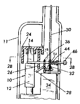
[0013] Fig. 2A shows schematically a side view of the interior of a lighter
having a lighter safety mechanism that is engaged according to the present
invention;
[0014] Fig. 2B is a cross-sectional view of the lighter shown in Fig. 2B
along line 2B-2B in Fig. 2A looking in the direction of the arrows;
[0015] Fig. 2C shows schematically a side view of the interior of a lighter
having a lighter safety mechanism according to the present invention in a
disengaged condition;
[0016] Fig. 2D is a cross-sectional view of the lighter shown in Fig. 2C
along line 2D-2D in Fig. 2C looking in the direction of the arrows.
DETAILED DESCRIPTION OF THE PREFERRED EMBODIMENT
[0017] Fig, 1A shows a side view of a piezoelectric lighter ignition unit 10
that is used in a lighter according to the present invention. P-iezc~elec~-
unit _
includes a main casting 12 and a plunger 14. Main casting 12 includes an
00612730.1
CA 02429290 2003-05-21
- 5 -
opening which receives an end of plunger 14 and allows the same to be
selectively moved inside main casting 12. As is conventionally known,
piezoelectric unit 10 generates electricity and transmits the same to wire 16
when plunger 14 is pressed and thus caused to move inside main casting 12.
The generated electricity is used to produce a spark to light a stream of
flammable gas. Unless urged by an external force, most of the body of
plunger 14 extends outside of main casting 12. Plunger 14 is spring loaded,
however, by a spring inside casting 12 so that when the external force that
urges plunger 14 into the main casting 12 ceases, plunger 14 returns to its
original extended position.
(0018] Referring now to Figs. 1 A-1 D, plunger 14 includes a notch 18 on a
side thereof. Notch 18 includes open surface 18a which is transverse to the
direction of movement of plunger 14 into main casting 12. Notch 18 is large
enough to receive stop portion 20 of latch 22. Referring specifically to Fig.
1 C, once stop portion 20 of latch 22 is received in notch 18, transverse open
surface 18a is opposed by stop portion 20 when plunger 14 is pressed in an
inward direction into main casting 12. The contact between transverse open
surface 18a and stop portion 20 obstructs the movement of plunger 14,
thereby preventing the production of a spark that lights the flammable gas.
As shown in Fig. 1 D, once stop portion 20 is moved away from transverse
open surface 18a, plunger 14 is free to move inwardly into main casting 12 to
produce a spark to light the flammable gas.
[0019] Piezoelectric unit 10 as incorporated in a lighter is shown in Figs.
2A-2D. Referring to Fig. 2A, piezoelectric unit 10 is disposed in the interior
of~.housing 1.1. The free. end of plunger 14 extends into a.xrigger24_.Trigger
24 is attached to the free end of plunger 14 to allow a user to press plunger
14
00612730.1
CA 02429290 2003-05-21
-6-
inwardly into main casting 12. Trigger 24 includes fuel release member 26
which extends in the direction of movement of plunger 14. As trigger 24 is
pressed to press plunger 14 inwardly into casting 12 to produce a spark, the
free end of member 26 contacts lever 28. This contact causes lever 28 to be
moved in the direction of plunger 14. The movement of lever 28 causes a
valve (not shown) to be opened to allow flammable gas to enter fuel tube 30
through nozzle 32 from fuel chamber 34. As plunger 14 is further pressed into
main casting 12, a spark is produced to light the flammable gas.
[0020] Referring now to Fig. 2B, latch 22 includes arm 36 which is integral
with stop portion 20 and extends from the interior of housing 11 to its
exterior. Arm 36 is slidably received by first 38 and second 40 snap-in latch
supports. First 38 and second 40 snap-in latch supports are spaced from one
another along arm 36 and are attached to an interior wall of housing 11.
Stopper 42 is attached to arm 36. Compression spring 44 on arm 36 is
disposed between stopper 42 and second snap-in latch support 40. Arm 36
also has knob 46 disposed at its free end to make it more comfortable for the
user to press the end of arm 36.
[0021] Now referring to Figs. 2B and 2D, in its natural, expanded state,
spring 44 presses against second snap-in latch support 40 and stopper 42,
thereby keeping the two spaced at a predetermined distance set by abutment of
stopper 42 with the interior housing 11. As a result, stop portion 20 is moved
into notch 18 where transverse open surface 18a (Fig. 1A) is opposed by stop
portion 20 to prevent the inward movement of plunger 14 into the interior of
main casting 12: _To release plunger 14, a user applies foroato..~.ab .46-
at.the_ _
end of arm 36. This force moves stop portion 20 out of the path of transverse
00612730.1
CA 02429290 2003-05-21
_ 7 _
open surface 18a (Fig. 1A) allowing plunger 14 to be pressed inwardly into
main casting 12. Also, this force causes stopper 42 to be moved toward
second snap-in latch support 40 causing spring 44 to be squeezed
therebetween. When the force is removed from knob 46, spring 44 returns to
its natural, extended state, thus forcing second snap-in latch support 40 and
stopper 42 to be spaced apart. While second snap-in latch support 40 and
stopper 42 are being spaced apart by the expansion of spring 44, plunger 14 is
allowed to move outwardly outside of the interior of main casting 12 thus
allowing stop portion 20 to be received in notch 18 (Fig. 1 A) and to oppose
transverse open surface 18A (Fig. 1 A). Hence, the lighter according to the
present invention cannot be operated unless plunger 14 is released by
application of force to knob 46 at the end of arm 36. It is noteworthy that a
lighter safety mechanism according to the present invention can be universally
incorporated in any purpose lighter in that its operation does not depend on
the configuration of the trigger or any other part of the lighter.
[0022) A movable latch of a particular configuration has been described.
Any other element that may be an obstacle to motion of the plunger and that is
movable between the stop and the open positions may be substituted.
[0023) Although the present invention has been described in relation to a
particular embodiment thereof, many other variations and modifications and
other uses will become apparent to those skilled in the art. It is preferred,
therefore, that the present invention be limited not by the specific
disclosure
herein, but only by the appended claims.
00612730.1