Note : Les descriptions sont présentées dans la langue officielle dans laquelle elles ont été soumises.
CA 02430514 2003-05-29
WO 02/44631 PCT/USO1/44219
1
COOLING AND HEATING SYSTEM FOR AN EQUIPMENT ENCLOSURE
USING A VORTEX TUBE
BACKGROUND OF THE INVENTION
Technical Field
The present invention relates to a cooling and
heating system and more particularly to a cooling and
heating system for outdoor enclosures, where the system
employs a vortex tube.
Background Art
Free standing outdoor enclosures for
telecommunications and cable television equipment
typically need cooling of the internal electronic
components. On the other hand, some items, such as
batteries may benefit from added heat in cold climates
to cause more efficient operation and to increase useful
life. Certain types of batteries are optimized by
maintaining their temperature at 77°F. Hence, depending
upon ambient temperature, such batteries may benefit
from heating at times and cooling at other times.
Typically, outdoor electronic enclosures in the past
have been cooled by air conditioning, thermal electric
coolers, heat exchangers and fans. These systems,
however, may be expensive, bulky, short lived and/or
environmentally hostile. Also, past systems are
directed to macro level cooling.
Vortex tubes are well known devices to those
skilled in the art and are explained in a number of
earlier U.S. patents including numbers: 1,952,281;
2,920,457; 3,173,273; 3,208,229; 3,654,768; 4,240,261;
CA 02430514 2003-05-29
WO 02/44631 PCT/USO1/44219
-2-
and 5,331,817, the disclosures of all of which are
included herein by reference. As explained in these
patents, a vortex tube is a device having no moving
parts. When fed with compressed air, the vortex tube
emits a stream of cold air from one end and a stream of
hot air from the other end. There can be enough of a
temperature difference between the two airstreams to
freeze water with the cold air stream and to boil water
with the hot air-stream. In operation the compressed
air enters a nozzle which injects the air tangentially
into a vortex generating chamber. The chamber is
positioned intermediate of the hot and cold ends of the
vortex tube but closer to the cold end than the hot end.
The air vortex created moves through the tube toward the
hot end but a sufficient back pressure is developed to
force some of the air toward the center of the tube and
then back in the opposite direction. This back flow
becomes very cold as it passes through the vortex tube
and it forms the cold airstream. An obvious benefit of
using a vortex tube is the environmental friendliness of
the refrigerant, ordinary air. Also, the refrigerant is
free and the vortex tube is a reliable machine.
Vortex tube cooling systems, however, are not
as efficient as ordinary refrigeration units. Also,
vortex tube systems are noisy and add more
inefficiencies if the necessary air compressor is
located at a distance from the vortex tube.
DISCLOSURE OF THE INVENTION
The present invention overcomes some of the
problems of the past by providing a very efficient and
compact cooling and heating system employing a vortex
tube comprising an enclosure having first and second
CA 02430514 2003-05-29
WO 02/44631 PCT/USO1/44219
-3-
chambers and items therein to be cooled and/or heated, a
vortex tube with a hot exhaust and a cold exhaust, the
vortex tube being operatively connected to the
enclosure, a compressed gas source operatively connected
to the vortex tube wherein the vortex tube cold exhaust
is connected to the first chamber in the enclosure and
the vortex tube hot exhaust is connected to the second
chamber in the enclosure.
An object of the present invention is to
provide a cooling and heating system employing a vortex
tube which is compact, lightweight, self contained,
relatively inexpensive and usable outdoors. Another aim
of the present invention is to provide a cooling and
heating system using a vortex tube where the hot
airstream is put to use instead of being dissipated to
the ambient environment. Still another advantage of the
present invention is to provide a cooling and heating
system using a vortex tube with an environmentally
friendly refrigerant, such as air. Yet another aspect
of the present invention is to provide a cooling and
heating system employing a vortex tube which is
relatively quiet, relatively inexpensive and reliable.
A still further object of the present invention is to
provide a cooling and heating system using a vortex tube
that can switch between heating and cooling as dictated
by climate, is scalable by changing compressors and/or
vortex tubes, is flexible in the range of heating and
cooling available, and is operable using AC or DC power.
A more complete understanding of the present
invention and other objects, aspects, aims and
advantages thereof will be gained from a consideration
of the following description of the preferred
CA 02430514 2003-05-29
WO 02/44631 PCT/USO1/44219
-4-
embodiments read in conjunction with the accompanying
drawing provided herein.
BRIEF DESCRIPTION OF THE DRAWING
FIGURE 1 is a diagrammatic view of a prior art
electronics enclosure cooled by a vortex tube.
FIGURE 2 is a diagrammatic view of a vortex
tube cooling and heating system of the present
invention.
FIGURE 3 is a diagrammatic view of another
embodiment of the present invention illustrating the use
of heat exchangers.
FIGURE 4 is a diagrammatic view of still
another embodiment of the present invention illustrating
the use of air jets.
FIGURE 5 is a diagrammatic view of yet another
embodiment of the present invention illustrating the use
of a vortex tube for heating and cooling depending on
climatic conditions.
BEST MODE FOR CARRYING OUT THE INVENTION
While the present invention is open to various
modifications and alternative constructions, the
preferred embodiments shown in the drawing will be
described herein in detail. It is understood, however,
that there is no intention to limit the invention to the
particular forms disclosed. On the contrary, the
intention is to cover all modifications, equivalent
structures and methods, and alternative constructions
falling within the spirit and scope of the invention as
expressed in the appended claims.
Referring to FIGURE 1, there is illustrated a
prior art vortex tube cooling device used for cooling
CA 02430514 2003-05-29
WO 02/44631 PCT/USO1/44219
-5-
electronic components, while dissipating a hot airstream
generated by the vortex tube to the ambient environment.
What is shown is an enclosure 10 having various heat
generating electronic components 12 mounted within the
enclosure. Fans 14,16 may be located within the
enclosure for circulating and expelling air. For
example, the fan 14 may be used to circulate air within
the enclosure while the fan 16 is used to expel warm air
from the enclosure. Generally, the enclosure is
substantially sealed so as to prevent moisture,
contaminants and adverse climatic conditions from unduly
effecting the sensitive electronic components.
A vortex tube 18 is mounted to the enclosure
such that a cold air stream represented by the arrow 20
emanating from a cold air exhaust 22 is directed into
the enclosure. A hot airstream represented by the arrow
24 emanating from a hot air exhaust 26 is dissipated to
the ambient environment. The input to the vortex tube
18 is compressed air represented by the arrow 28. The
compressed air divides into two airstreams due to the
geometry of the interior of the vortex tube. Georges
Joseph Ranque of France is credited with being the
inventor of the vortex tube and his device is explained
in his 1934 patent, No. 1,952,281. The problem with the
prior art cooling device is that the hot airstream is
dissipated to the ambient environment, the device is
noisy and the compressor generating the compressed air
is removed from the vortex tube.
The features of the present invention include
a compact, self-contained arrangement suitable for use
outdoors. Also, the hot airstream from the vortex tube
is used and the arrangement reduces the noise generated
by this hot airstream. Further, the system is reliable,
CA 02430514 2003-05-29
WO 02/44631 PCT/USO1/44219
-6-
relatively low in cost and environmentally friendly
because the working fluid or refrigerant is ordinary
air.
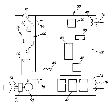
The present invention is understood by
reference to FIGURE 2. There is illustrated an outdoor
enclosure 30 such as those used for telecommunications
equipment where the enclosure includes an upper chamber
32 and a lower chamber 34. The upper chamber contains
heat generating electronic components 36, 38, 40, 42
while the lower chamber 34 contains a series of
batteries, such as the battery 44. The upper chamber
may also include a circulation fan 46 and an exhaust fan
48. The batteries serve the purpose of operating the
components even if there is an interruption of
commercial power.
The cooling and heating system 50 of the
present invention is shown in a third chamber 52
although it is understood that the cooling and heating
system may be placed in the lower chamber 34 if desired.
It is to be noted that outdoor enclosures or cabinets
may consist of several chambers, such as combinations of
a sealed upper chamber, a vented lower battery chamber,
a vented lower fuel cell chamber or vented side and/or
back chambers. The cooling/heating system of the
present invention may be placed in the lower chamber, a
side chamber or a back chamber because of its relatively
small and compact sire. It is also to be understood
that the cooling/heating system may even be housed in
its own enclosure or cabinet adjacent an equipment
enclosure. It is to be noted that if the upper chamber
is sealed, the exhaust fan 48 is eliminated or it may be
used to recirculate air to an air inlet of a compressor
as will be explained below.
CA 02430514 2003-05-29
WO 02/44631 PCT/USO1/44219
_'j_
The system 50 includes an air inlet 54, a air
filter and dryer 56 and a compressor 58. The air from
the compressor is then stored in a tank 60 which is
connected to an inlet 62 of a vortex tube 64. A cold
airstream represented by the arrow 66 emerges from a
cold air exhaust 68 and is directed into the upper
chamber 32 for cooling the electronic components. A hot
air-stream represented by the arrow 70 emerges from a
hot air exhaust 72 of the vortex tube and this airstream
is introduced into the lower battery chamber 34.
The ambient air is cleaned and dried by the
filter and dryer 56 in a manner know to those skilled in
the art. The air compressor 58 is relatively small but
has sufficient capacity in terms of pressure and flow
rate to ensure cooling of the electronic components and
good performance of the vortex tube. The compressor
provides the compression and pumps the air into the tank
60 which is used to build up the air pressure and to
maintain a constant supply of compressed air. There is
also a slight bit of air cooling that occurs in the
tank. From the tank the compressed air flows into the
intake 62 of the vortex tube which should be of a
suitable size consistent with the heating and cooling
needs of the particular components and batteries and the
size of the enclosure chambers. After heat is picked up
from the electronic component chamber 42 and/or after
warming the batteries in the lower chamber 44, the two
airstreams may be exhausted to the surrounding ambient
environment through appropriate vents 74, 76 in the
enclosure, or the upper airstream can be recirculated to
the air inlet 54 for the compressor 58 if the chamber 32
is sealed. In such a circumstance, the vent 74 is
eliminated.
' ~CA 02430514 2003-05-30
o,.., ,: !! ,L.... ".," ,. ! n a ,...,I: a r ..n ....,I:
,s .t.w,. ...!!... ! I .,fit = i!..5 ., u.. .. . ~ . 'i~ n,~ I 1! ~.n!1~
~f°~il 1~;::;! it~;iI :f'.~'~ ~~'..~, rr,..
!l..-' 1"..:~ I,i ' , .., y..: ~ ~ :::!1 ~~., ~ ...c!.. :' s~ !.( i;...
....,.. ~ ., 1. ;.. .., ,., .. ,.. .... ,.... ... ,.. ..,...
Another advantage of the present
cooling/heating system is that it may use a DC
compressor to ensure that cooling and heating occur even
if there is a loss of commerc zal power. In other words,
the compressor may be powered by the batteries. It is
to be noted that the use of the inventive
cooling/heating system overcomes the lack in the
marketplace of a small scale expansion device for small!
scale compressed air systems. The smallest turbo
expander availabley~is 18 inches in diameter and two feet
long. It requires a flow rat a of at least 200 cubic
feet per minute (cfm) and has a rotational speed of
120,000 revolutions per minut a (rpm). Any smaller
expander would require operat ion at still higher speeds
which creates lubrication and vibration,problems and
would engender relatively high development costs. Also,
high rotational speeds cause reduced equipment life.
Alternative systems tend to be heavy, bulky and
expensive. Also, vapor compression cycles use
refrigerants which may cause environmental damage. In
addition, such refrigerant units are not suited for
operating with a DC backup. Furthermore, refrigeration
units are usually packaged separately and thus not
easily integrated with an equipment enclosure where
space is at a high premium. Moreover, the heat
generated by a conventional system is wasted.
By way of example, a Marconi Mesa Sport brand
enclosure nominally requires about 600 watts of cooling.
This can be accomplished using a compressor operating at
a flow rate of 30 cfm at a pressure of about 100 pounds
per square inch. Such a compressor may be obtained from
Scrollex Corporation of Will owbrook, Illinois and is
known as Scrollex model MTA1 0 H. A vortex tube from
-~~6~~~~ ~r .~~.,
CA 02430514 2003-05-29
WO 02/44631 PCT/USO1/44219
-9-
Exair Corporation of Cincinnati, Ohio, model 3230 may be
matched with the compressor. The result is cooling to
close to 0°C. or to a temperature that avoids frosting
of the system and avoids impedance of flow through the
system.
The compressor and vortex tube can be scaled
and can be used flexibly to vary the cooling capacity of
the system. A hot airstream at about 40°C. will provide
the best performance and longest life for lithium-
polymer type batteries and fuel cells.
Referring now to FIGURE 3, there is
illustrated an enclosure and cooling/heating system
where structures in FIGURE 3 are designated by like
numerals for like structures shown in FIGURE 2.
However, instead of introducing the air flows from the
vortex tube directly into the upper and lower chambers
of the enclosure as was done in the FIGURE 2 embodiment,
in the FIGURE 3 embodiment the cold air exhaust 68
directs the air to the input of a heat exchanger 80.
The cool air absorbs heat from the air of the upper
chamber 32 before the air is exhausted to the ambient
environment. Alternatively, the air in the chamber 32
may be fed to the heat exchanger and returned to the
chamber while the former cold air from the vortex tube
is exhausted to the ambient environment after it picks
up heat in the exchanger. This allows the chamber 32 to
be completely sealed. The hot air from the hot air
exhaust 72 is directed to a heat exchanger 82 in the
lower chamber 34. The heat exchanger 82 in the lower
chamber may take the form of a thermally conductive
plate upon which the batteries, such as the battery 44,
are mounted. This allows for conductive heat transfer
which is more efficient than the convection heat used
CA 02430514 2003-05-29
WO 02/44631 PCT/USO1/44219
-10-
with the FIGURE 2 embodiment. Also, the conductive
plate may be used with the cold air flow.
Referring now to FIGURE 4, there is yet
another embodiment of the enclosure and the
cooling/heating system. Once again like structures in
the FIGURES are identified by the same numerals as used
in FIGURES 2 and 3. Instead of introducing the cold
airstream directly into the upper chamber 32 as done in
FIGURE 2, or into a heat exchanger as done in FIGURE 3,
a conduit 90 is provided with preselected openings so as
to form air jets. These openings can be placed adjacent
specific electronic components, or nozzles may be used
to direct a blast of air to the components so that these
components are cooled to a lower temperature than the
average temperature of the chamber. The same would be
true of the FIGURE 3 version where particular components
can be placed, for example, on cold plates so that there
is better heat transfer and the particular component can
be brought to a lower temperature than the average
temperature of the chamber in which the component is
located.
Another advantage of the present system is
that the system can direct hot or cold air wherever it
is desired or required due to changing climatic
conditions. The system can also be automated so as to
respond to climatic conditions. Referring now to FIGURE
5, another embodiment of the present invention is shown
where structures in FIGURE 5 are designated with the
same numerals as are used to designate like structures
in FIGURES 2-4. The variation in FIGURE 5 illustrates
that the hot air flow from the hot air exhaust 72 may be
directed to both the upper and the lower chambers 32, 34
by conduits 100 and 102, respectively. The same may be
CA 02430514 2003-05-29
WO 02/44631 PCT/USO1/44219
-I1-
true of the cold airstream and/or the cold air may be
used to cool the compressor 58. Conduit 104 runs to the
upper chamber 32, Conduit 106 runs to the lower chamber
34 and conduit 108 communicates with the compressor 58.
Whether components are heated or cooled may depend upon
the ambient temperature and climatic conditions, namely,
whether the season is summer or winter. A temperature
and/or humidity weather sensing device 110 may be used
to regulate valves 112, 114 which determine whether a
chamber is heated or cooled and to what temperature.
The specification describes in detail several
embodiments of the present invention. Other
modifications and variations will, under the doctrine of
equivalents, come within the scope of the appended
claims. For example, the flow rate and pressure may be
varied to adjust the temperatures of the air emerging
from the cold air and hot air exhausts. Also, various
arrangements can be made with air jets and/or cold and
hot plates and/or heat exchangers and the like depending
upon the particular components to be cooled or heated
and depending upon their location within the enclosure.
The arrangement includes mixing and matching air jets,
cold plates and the like. Also, the weather sensing
device may be used to sense one or more weather related
factors. All of these are considered to be equivalent
structures. Still other alternatives will also be
equivalent as will many new technologies. There is no
desire or intention here to limit in any way the
application of the doctrine of equivalents.